Parts layout & wiring has made a lot of progress. Power switch is working. The halves still close.
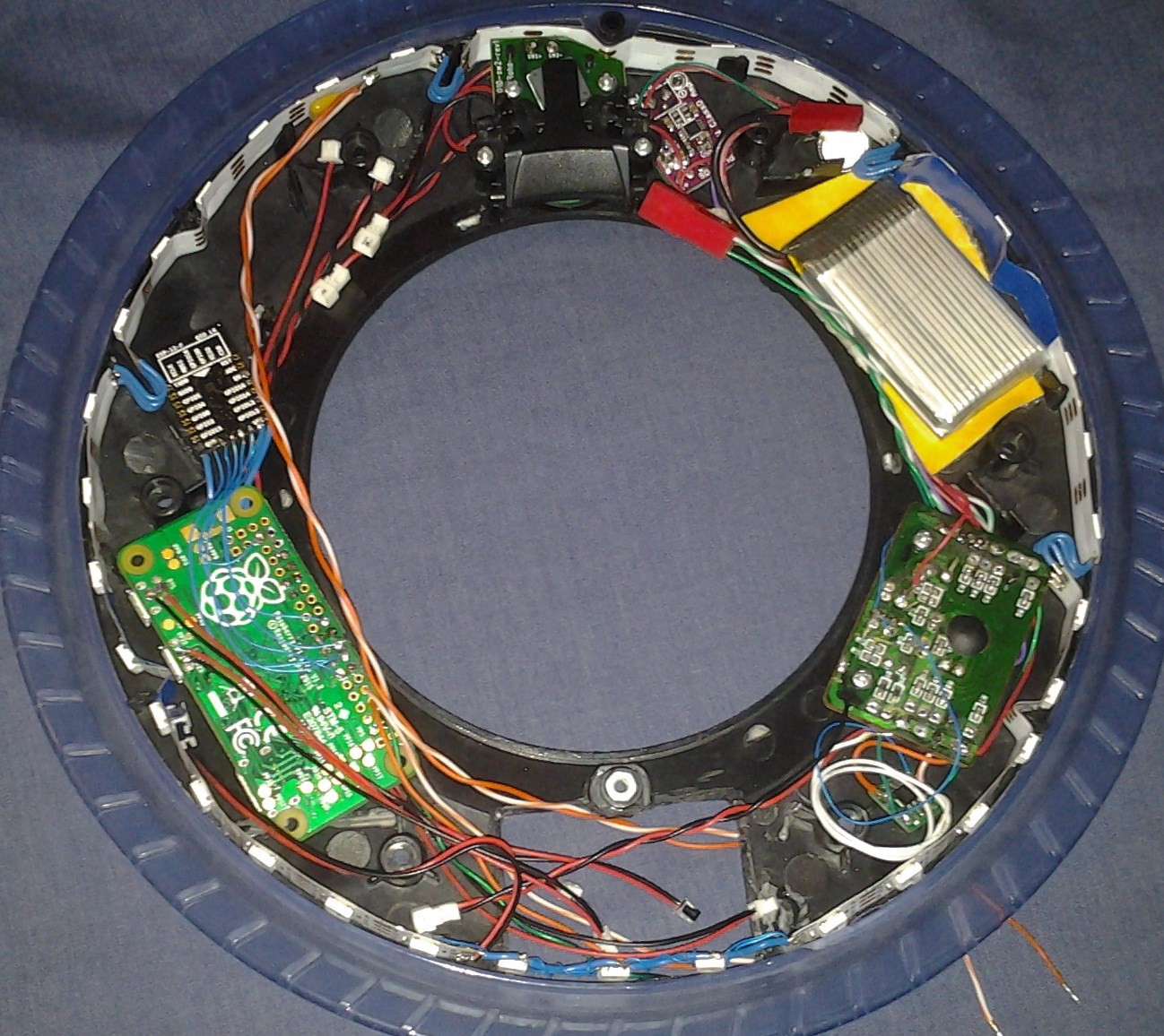
In the pic below:
- button/speaker
- audio amp
- pager motor
- battery
- Using the LED common connections on the old main/switch board as a power bus.
- charger is beneath the switch board
- dual FET for main power switch and pager motor
- battery door space for: RTC, accelerometer, external USB connector
- RPI Zero (USB power, data, and SDIO wiring visible, other connections on the other side)
- ESP8266 for SDIO WiFi
- audio and button connectors, LED power
Discussions
Become a Hackaday.io Member
Create an account to leave a comment. Already have an account? Log In.
Amazing! Looking good!
Are you sure? yes | no