 kelvinA
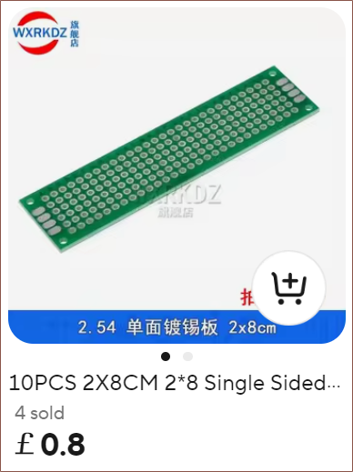
I was planning to just break and stick stripboard around the place, but I found out about 2x8cm perfboard and found a listing for 5pcs black double-sided for 76p and another for 10pcs green single-sided for 80p:
 It just sounds like double sided isn't a need-to-have and would just make desoldering mistakes harder, so I went to design using the single-sided version. After about 4 hours, this is what I've got:
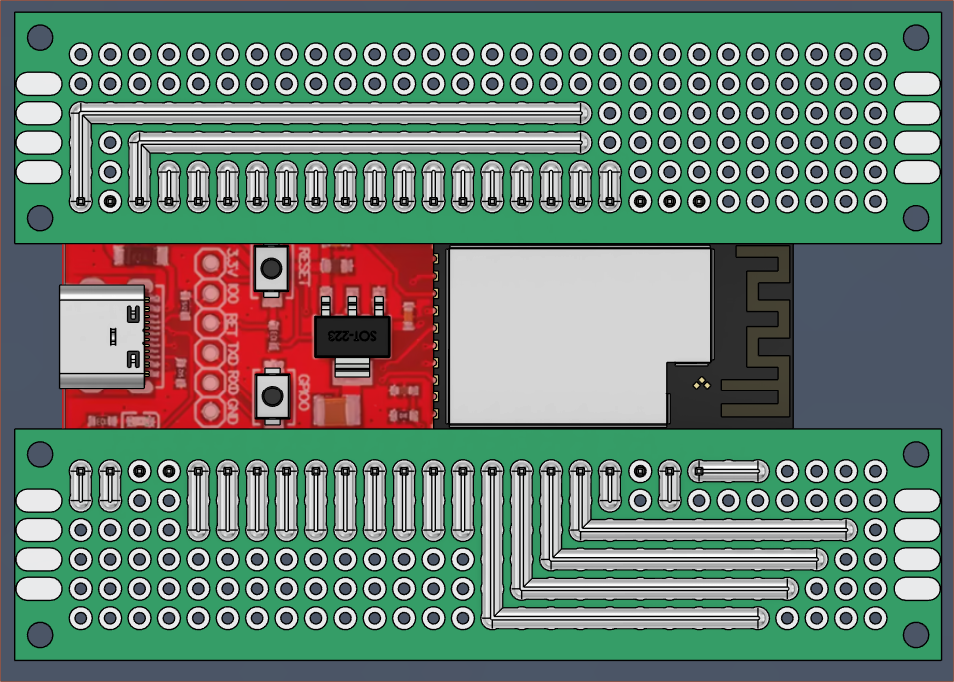 Before I went to bed, there were also some jumper wires so that I could take GPIO18 and VCC and move them closer to GPIO0 in the pursuit of bundling the RGB ring and luminance sensor in one 6-core cable, but I decided it'll be better to use GPIO45 and just strip some of the wire 50mm longer. GPIO46 is input only, so I assume I can't use it for ARGB data out. I also think the D-in of the WS2812 is high impedance so it hopefully doesn't affect the strapping function of IO45.
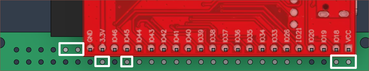
The reason the TEMT6000 is using 3.3V is because Proto Supplies found that the max voltage when VCC=5 was 3.8V. Assuming linearity, with VCC=3.3, I'd expect a 0 - 2.5V output range.
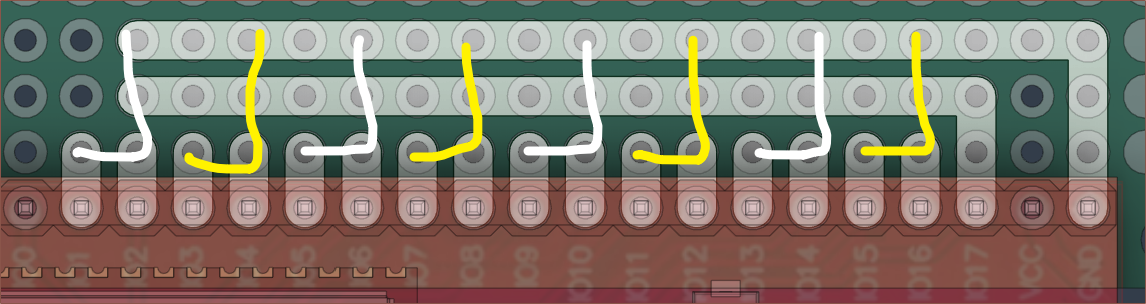
Also on this side are the columns and rows, shown in yellow and white respectively. Each "row" is one keywell.
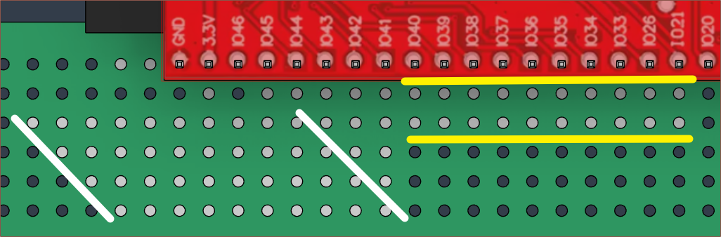
Moving onto the other perfboard, the 4 pins needed for each of the 8 joysticks is shown below:
Coincidentally, the mounting holes are M2, same as what I need for the joysticks. Thus, where possible, I'm going to try using self-tapping M2 holes to affix parts together with the M2x14 tapping screws.
Discussions
Become a Hackaday.io Member
Create an account to leave a comment. Already have an account? Log In.