Close
0%
0%

Tetizmol [gd0153]

A Tetwice-layout keyboard designed to be abysmal.

Similar projects worth following
Opinion: typing on a keyboard with nails >5mm long is abysmal, i.e. "very bad". This mostly stems from key-slippage typos, but the force exerted where the nail connects with tissue become uncomfortable too. Inspired by Svalboard (and Master Forge), this project is a keyboard that uses 4 long microswitches around each digit to sidestep this problem. Furthermore, having the phalanges in wells means that they can be insulated from the cold, empowering one to type in the crisp outdoors.

While I named this project to reflect my low expectations, the other definition of abysmal is "very deep", which is coincidental as the wells are bottom-key-less.

Navigation

The title tag system is explained here, and the table is updated when a change occurs. Notable logs have bold L# text.

L1
[X][R] Microswitch choice and placement
L2
[P] 55mm KW11 Microswitch
L3
[X] Bending the lever
L4
[M] Keycap
L5
[P] Keycap test prints
L6
[X] Keyboard PNP transistor matrix
L7
[M][T] Dual spacemouse tube?
L8
[B][R] PS5 Hall Joysticks and Espressif ADCs
- Planned pins for ESP32-S2
L9
[R] Hall / TMR joystick electrical properties
L10
[R] Component Considerations
L11
[L] Perfboard Circuit
L12
[B][P] 6-core cable and joystick PCBs
L13
[C] KMK SpaceMouse Compact emulation
L14
[C] Pog Configurator for a chording keyboard
L15
[P] Joysticks, ball joint arms and clamps
L16
[C] Reduced pog.py RAM use and increased DecayRing FPS
L17
[A][C] TwiceLayer and TrueLayer
L18
[X] Balls secured to joysticks

Preface

[Nov 27]

I've tried a Let's Split keyboard. I've tried a WK-50 keyboard. I want to try a Svalboard but it's not cheap nor portable enough to use anywhere but on a desk or affixed to an armchair.

My efforts developing #Tetent [gd0090] advance at a glacial pace. Thus, I'm still using my (not so temporary) "temporary" Z-88 (typewriter style) keyboard I bought 3 years ago. Furthermore, there's still a lot more typing/programming I need to do between now and [insert time when Tetent exists]. There's now a very wide feature gap between Tetent and a split mechanical keyboard, so there must be some kind of stopgap solution that can slot in-between.

Looking through keyboard images on the internet, I don't think I'm going to get a user experience much different to what I've already tried and used; it's essentially the same keys just rearranged slightly differently if the designer was feeling daring, or just a different colour/shape on the keycaps of the tried-and-true QWERTY stagger if not. Basically, I look at a keyboard, look at my nails, look at my to-do list and think "Mn, probably not going to pad out.".

Then I remembered the passing thought I had while browsing the DataHand / Svalboard discord around February time:

I wonder when someone will try to make a "poor man's" DataHand using microswitches.

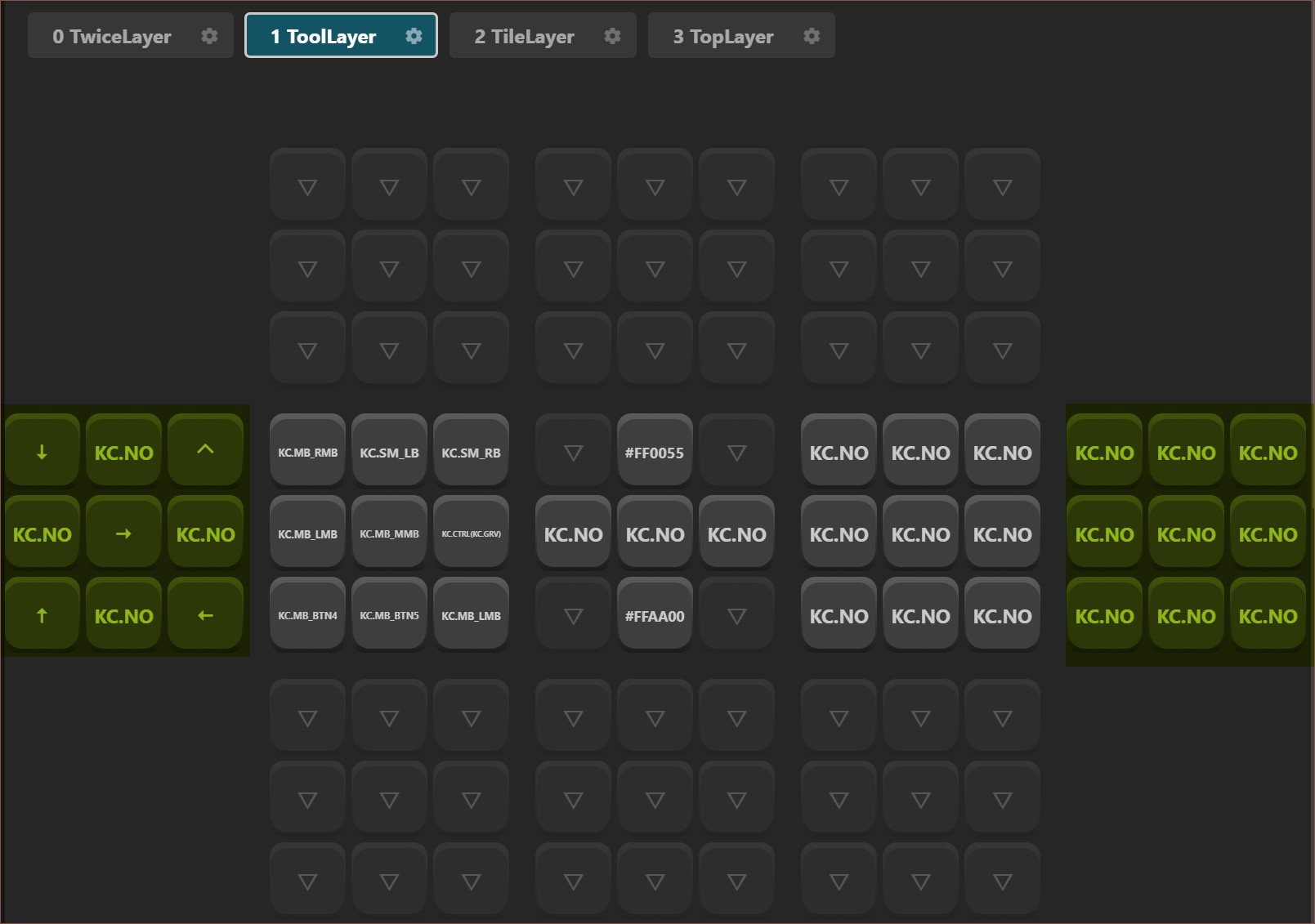
I also still want to learn Tetaip -- the layout I formulated during #WK-50 Trackball Keyboard -- as a bit of a hobby. With twice the switches, I think I could formulate a layout that enters twice the characters per chord, hence the name "Tetwice".

I've also somewhat sold myself on that "digital nomad" lifestyle, and Britain has some rather nice weather that is overshadowed by 10C temperatures. 

Due to all this, I've now started researching into this project.

  • [X] Balls secured to joysticks

    kelvinA04/29/2025 at 18:26 0 comments

    First thing I did was download the drill guide .STEP and confirmed that dimensions seemed sensible, so I printed it and the joystick was a nicely snug fit: 
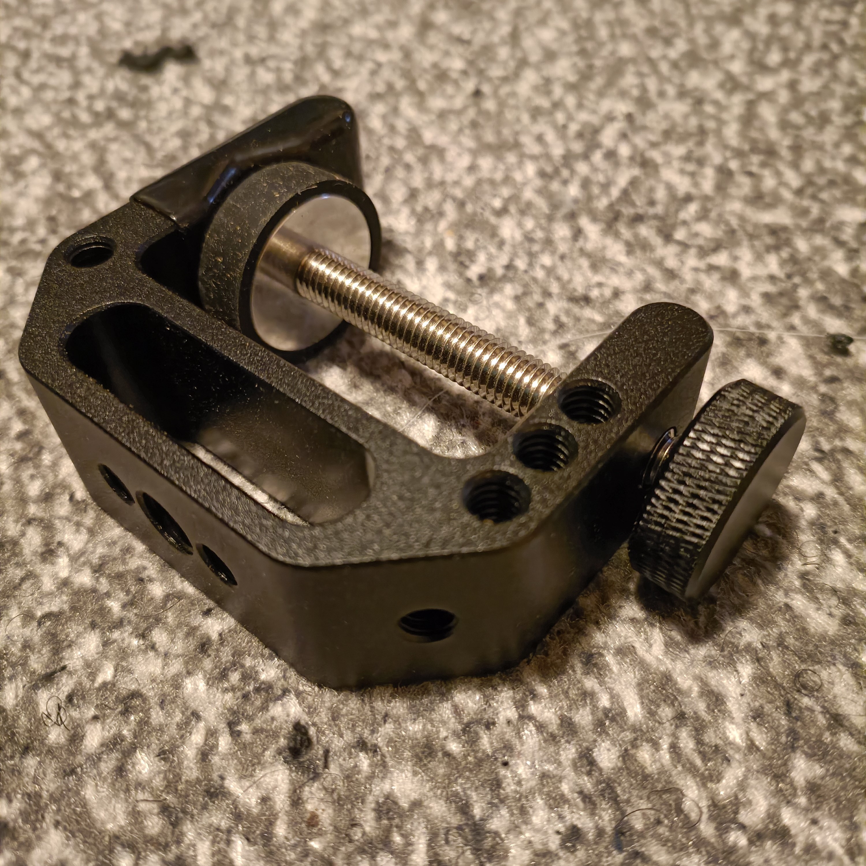
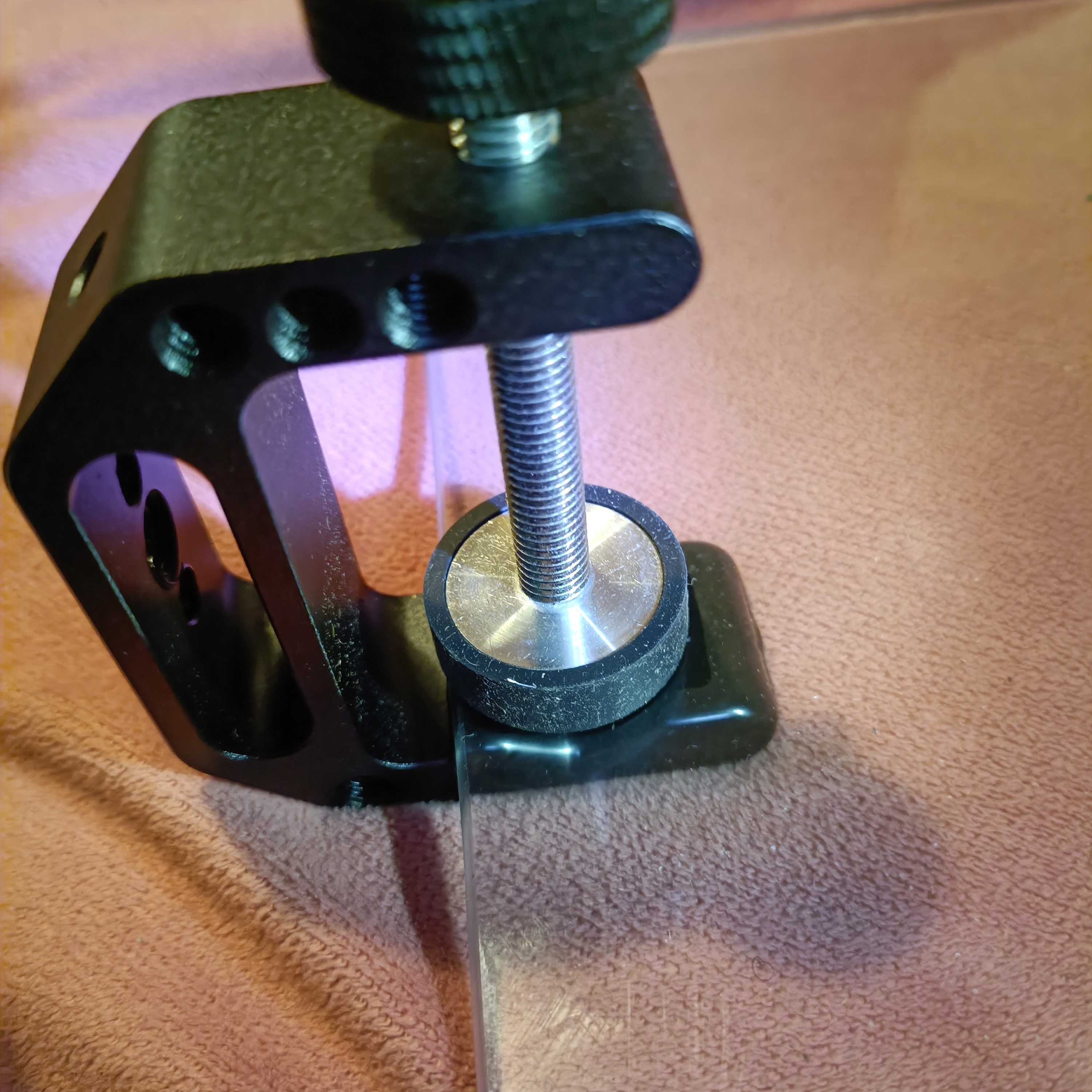
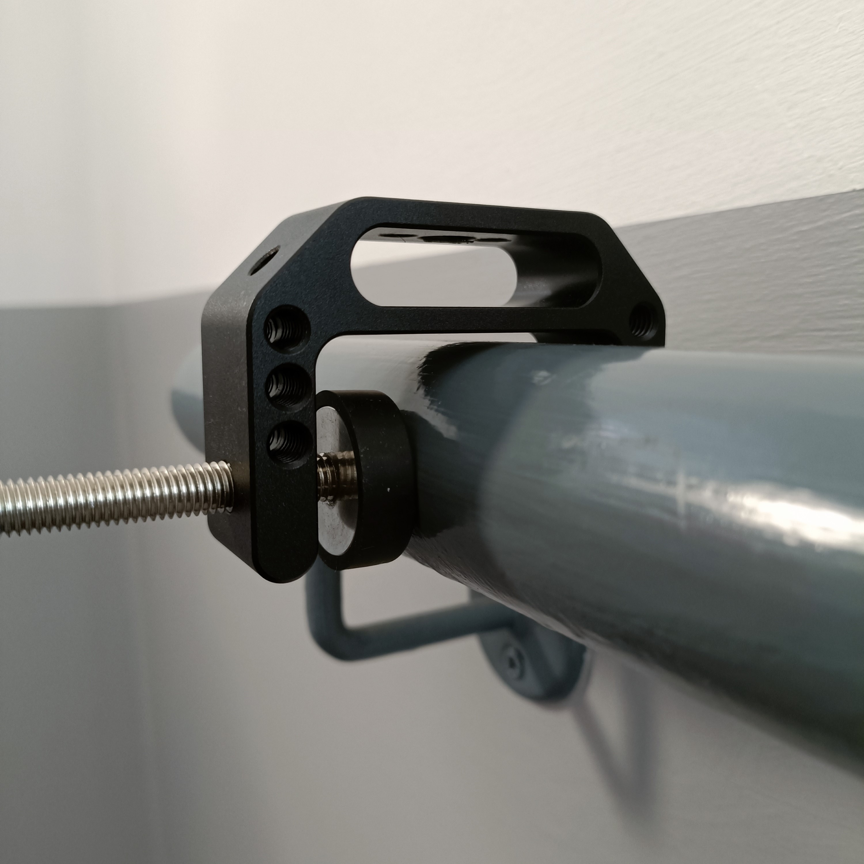
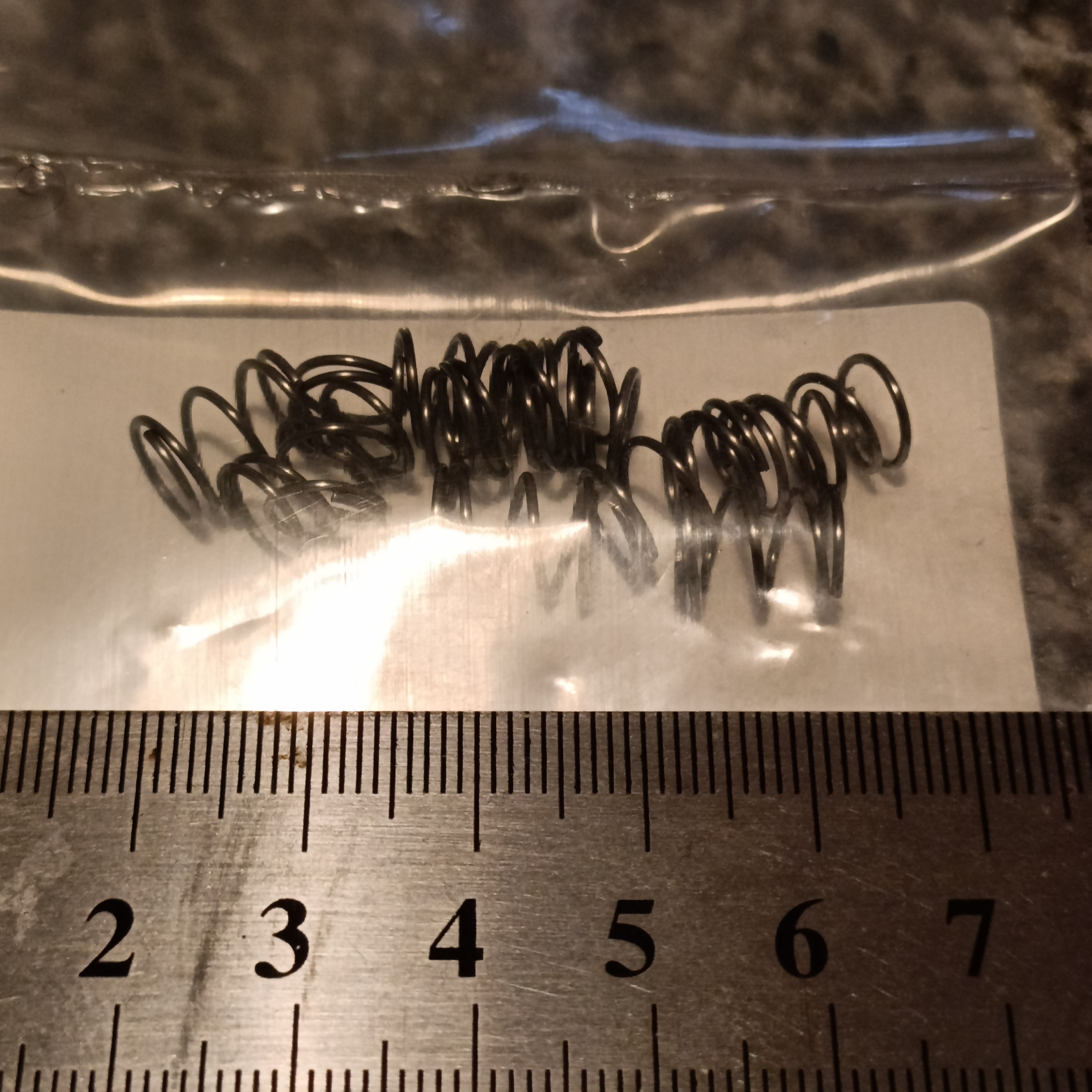
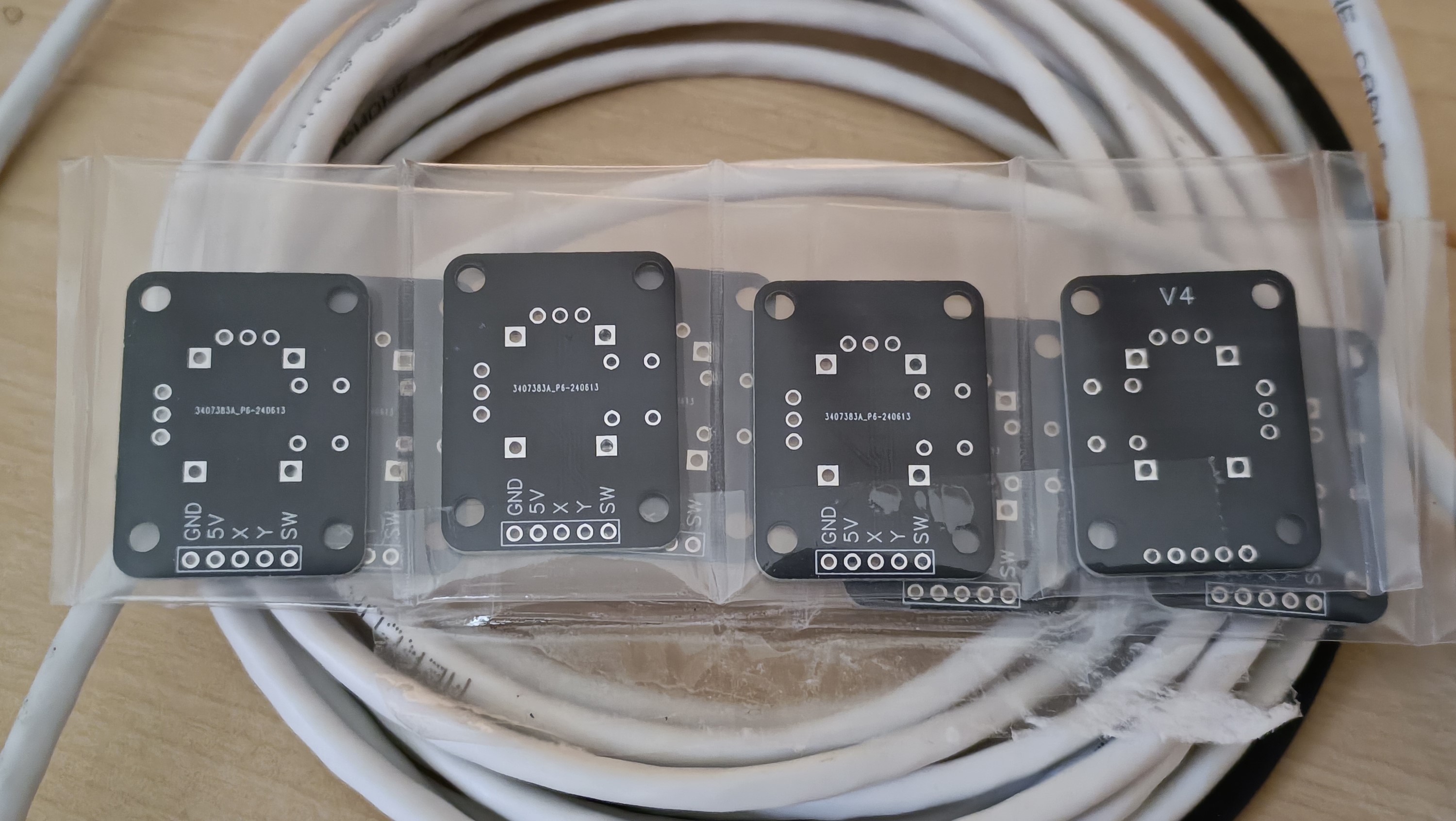
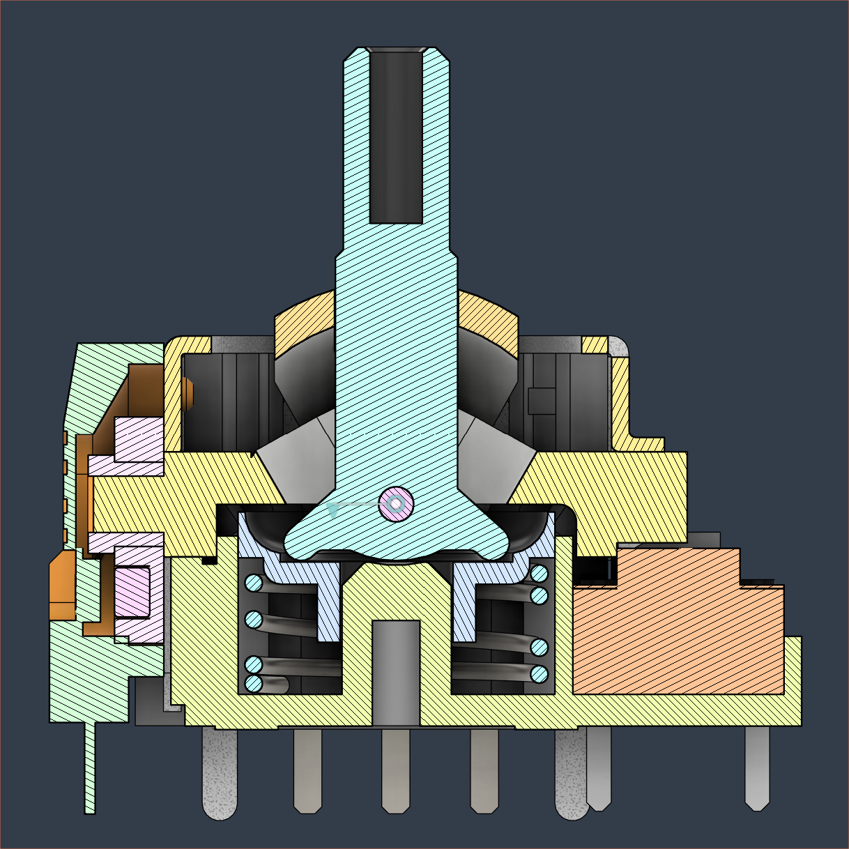
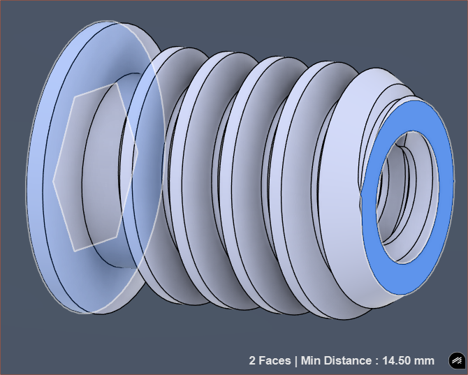
The printed hole needed to be drilled, which is probably by design to have the best tolerances. I tried 1.5mm, which barely fit in the drill, and then opened it up a bit more with a 1.6mm bit. 

    The 1.5mm was black and the 1.6mm was almost brass in appearance; the drilling difficulty felt like cold and room-temp butter respectively.

    Then, I tried drilling the joystick to 1.5mm, which worked, but the screw wouldn't start. I tried again with the 1.6mm and it started to screw down after maybe 10 seconds of spinning:

    Immediately after I finished screwing, I thought "Haven't I got the washer on the wrong side?" and so I checked:

    Well everything seemed perfectly stable and the plastic didn't seem like it was going to break or anything. I actually asked this question and never got a response (see below) so I decided I was going to spend the £1 on washers just in-case.

    I decided to try having the ball as the washer, because it would be even more tedious to put the washer between the joystick and ball during assembly, and it looked and felt fine:

    So I did the other 9 sticks, following these steps:

    1. Sort out the balls. I filtered out 3 balls that were nominally 7.90mm while finding 10 that were 7.97 - 8.02.
    2. Drill all joysticks using the 1.6mm drill bit. I kept the drill spinning when pulling the stick out in an attempt to avoid jamming and keep a good interior surface finish.
    3. Put a joystick in a vice. I like to have the orientation as shown above so that I can see early if I'm crushing the yellow plastic.
    4. Put a screw in the ball and hold the ball to help guide the screw as I spin for a couple seconds.
    5. If the screwdriver skips 3 times, unscrew. 
      1. There's 100pcs of screws so I'd rather get a new one. The more the driver skips, the worse the phillips head becomes and the more likely it is to skip in a negative feedback loop. I rejected 3 screws due to this, with the last one being very close to being perma stuck.
    6. When the screw stops turning, it's good. The ball doesn't move or twist and I don't have to do any "final tighten" or anything.
    7. Take the joystick out and GOTO step 3.
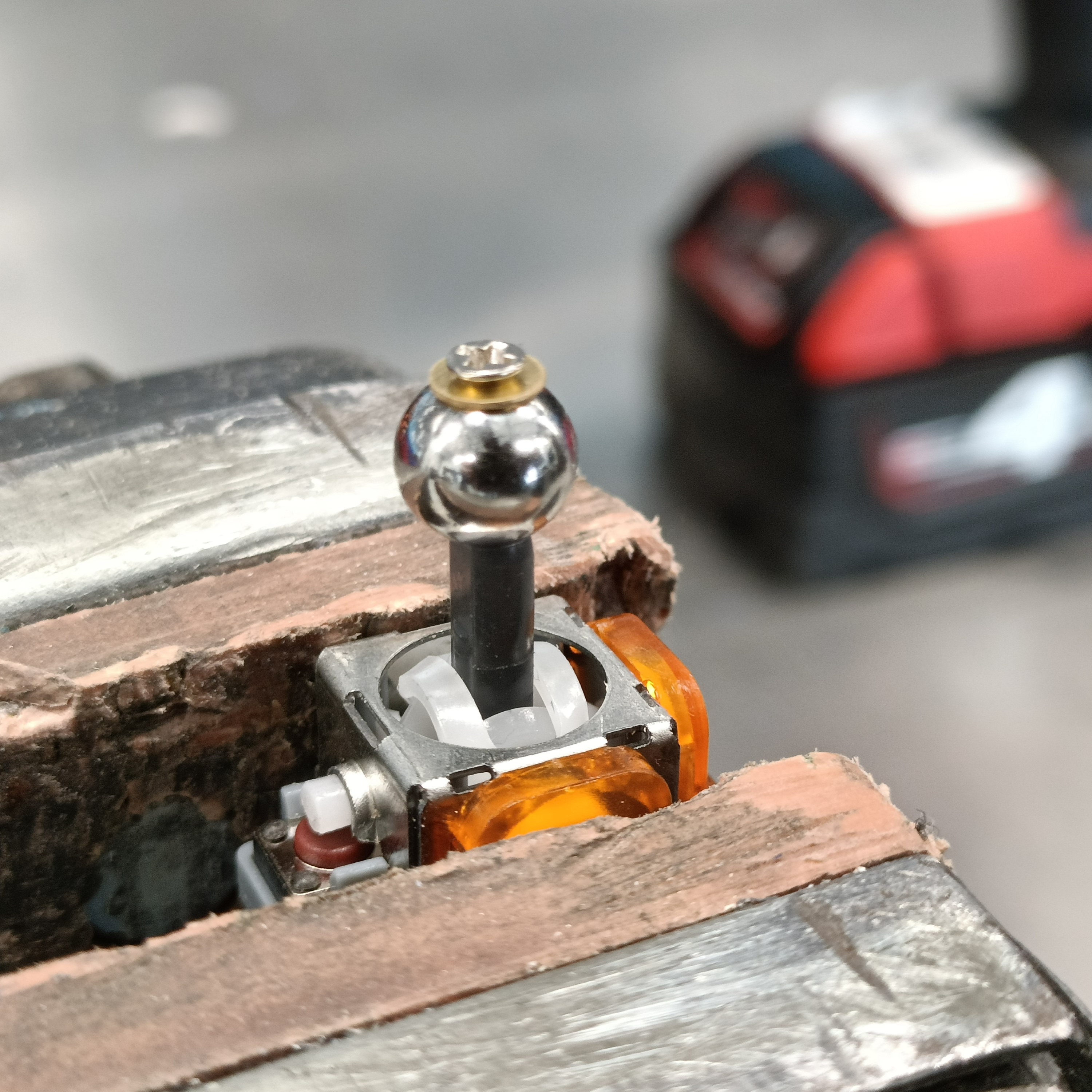
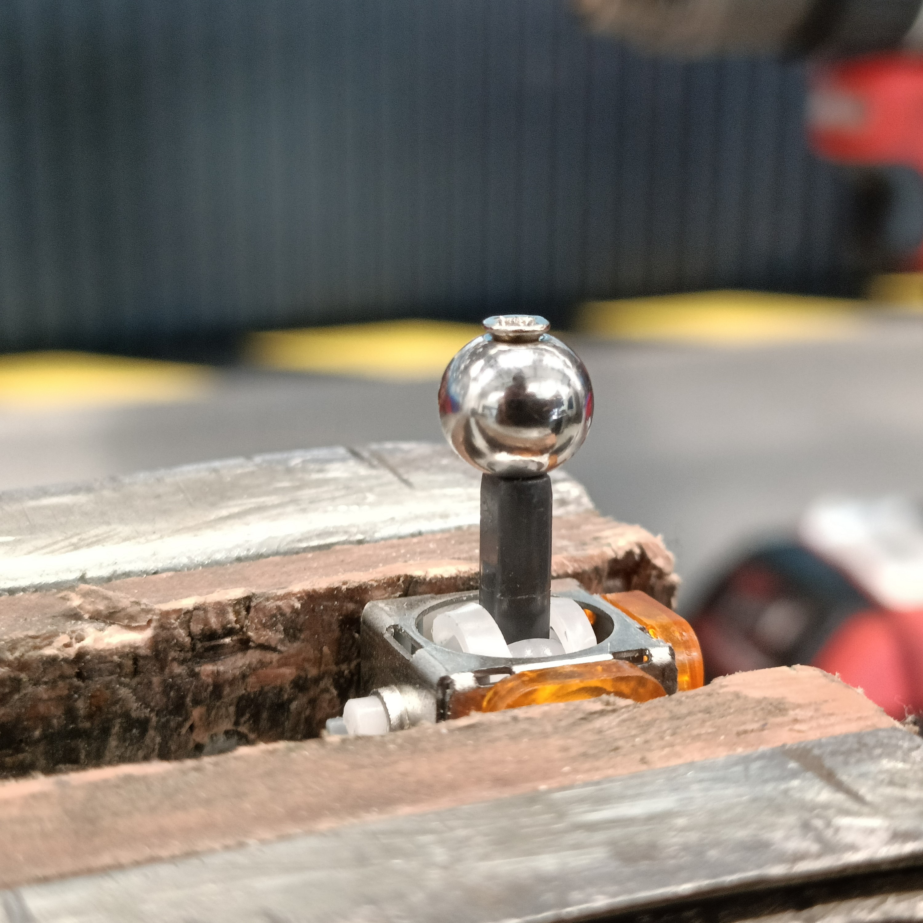
    Lastly, I tried the bushings with the first stick I did (which is the joystick I opened in a previous log) and it slid rather nicely. This strategy is soooo much better than having to try and install smoothly printed adapters.

  • [A][C] TwiceLayer and TrueLayer

    kelvinA04/06/2025 at 07:19 0 comments

    The currently populated layout, which skips 5Y chords.

    TrueLayer

    As you can see, I've moved things around, mainly so that one doesn't have to go to another layer to access symbols. You might also notice that "TrueLayer" has been renamed "TwiceLayer" because I've now coded in the true "shadow dimension" layer, which is 18 keys with no chord-mapping, intended for things like game controls. 

    As mentioned previously (I hope), the numbering for the wells on the right hand matches that of a numpad. Thus the 4 physical buttons map to a keywell value of 1, 3, 7 and 9. For Well4, a value of 3 is the TileLayer and 9 is the TopLayer. What happens if you try to go to both the Tile and Top layers at the same time? Well4 = 6 is when spacetime momentarily collapses and you enter the TrueLayer.

    As you know, there are 20 keys on each side. Thus, 18 are 1:1 mapped and the last two, residing on Well4, escape the layer:

    # Bottom Right: 12 34 56 78 9E

      This is partially so that the bottom and top fit in a box of 9 (see below) and partially so that pressing Well4 = 6 again causes another rift in the spacetime and a negative of a negative is a plus, thus you end up in TwiceLayer again.

    The ToolLayer with the TrueLayer section highlighted green. The bottom is on the left and top is on the right side.

    Parsing Alt Codes

    There are buttons like A241 on there. When these are parsed, the below regex finds a match:

    if re.match(r'[aA]\d\d\d\d?', key_string):

    Now, this isn't the first output Ai tools gave me. It turns out CircuitPython's implementation is incomplete so I had to ask Copilot to avoid the asterisk:

    NOT SUPPORTED:
    -  counted repetitions: {m, n}

    Due to this, I've inverted the logic on the Num-lock LED. Now it's orange and illuminates to signal "the num-lock is off so parts of the layout won't work correctly" to the user, similar to the CAPS lock warning when entering a password.

    Letter and Symbol Placement

    The most notable addition is the CTRL on Well4 = 4, so that things like CTRL-A + CTRL-C could be entered. I feel like this feature would be more useful for the CTRL-K shortcut in Visual Studio Code. The location of K is related to the location of C, which is on top because of "copy" and V is on bottom because of "paste". X is in the middle because it's like scraping of a sticker with a fingernail. Finally, Z is to the left so that "undo" isn't hard to do.

    For the location of the keys, I've assumed the following list of easiest-to-hardest chords per keywell:

    1. Bottom keys are easier to hit than top keys, and it's easier to stay on the same side of the well. Thus, I've picked =1 as the "easiest" key. There's little reason why it couldn't've been =3 instead.
    2. Keywell values that use more keys are less reliable to chord. Thus =5 is the hardest.
    3. For any XY chord, 0Y and X0 chords are easier just because only one finger needs to move.

    Thus, you might be wondering why a bunch of punctuation, or seldom-used characters like K and Q, are on these easy 0Y/X0 sections. It's simply to prioritise flow. Let us talk QWERTY for a bit. Due to its frequency, the E key could likely be anywhere and, from practice, not affect speed. In contrast, the Q key is seldom used and feels like a trip hazard when the shortest finger has to reach out for it, unlike the equally unused J key.

    Anyway, this is the list of considerations (in no particular order) that I made, with help of the character frequency of past logs I wrote and bigram frequency:

    Character before 'e' is [space] and character after 'y' is [enter]
    1. Constants on 7Y to match with T placement. Vowels on 1Y to match with E placement. 
      1. Like with ZEV-XS, I put them on lesser utilised fingers to balance out the workload.
      2. Y is essentially a vowel
    2. As H is in the top 2 bigrams, making up 5%, I had to put that in the 7[1/4/7] row instead of S.
      1. H = 77 so that, somewhat satisfyingly, "th" = 7077 and "he" = "7710"
    3. Similar position for Q and U (0616), X and Y (7515),...
    Read more »

  • [C] Reduced pog.py RAM use and increased DecayRing FPS

    kelvinA03/04/2025 at 13:03 0 comments

    As I (and Charachorder founder has) mentioned in the past, ease-of-learning is paramount for anything that requires a new skill. This is why I wanted to have an LED ring that acted as a peripheral-readable display for showing:

    • which of the 9 states each well is in
    • the lock states (eg. the CAPS lock LED)

    I knew that I wanted the LED's to look like a (powerful) bulb:

    • It turns to full brightness immediately
    • Its brightness "decays" when turned off. 

    Bulbs heat up the filament quickly but take a fraction of a second to cool down again. LEDs turn off immediately unless they're connected to a capacitor (such as a capacitor inside a PSU):

    The issue is that an immediate turn-off a) doesn't look as nice and b) will call attention because the LED was on and suddenly it's completely gone. At the same time, the decay profile needs to happen fast enough so that it's that it's turning off. As you can see in the above video, the capacitance is so large that it takes a few seconds to notice that the LED's brightness is decreasing. It's also why using a linear decay wouldn't look as good as an exponential one (like a capacitor).

    I wanted to feed constant ambient light data from the TEMT6000, so the brightness value of the LEDs would also have to constantly change. Furthermore, I wanted the LED ring to have a standby white value so that all 16 LED positions are always visible when Tetizmol is on so that it's still visibly a circle even if nothing is pressed. All in all, this whole idea is a "live animation", and the KMK RGB extension isn't; it doesn't take into account things like key presses the way my Z88 Typewriter-style keyboard does. So while I started from rgb.py, almost none of it remains.

    Pog.py

    As expected, when I started modifying KMK's RGB extension to become a new thing called DecayRing, I hit the dreaded MemoryError. 

    I noticed that I had more memory free when I removed a layer in pog.json. So I started reading into pog.py and memory reduction strategies and added the lines with the comments:

    config = {}
    configbuffer = bytearray()
    configbufferlen = 0
    try:
        with open("/pog.json", "r") as fp:
            x = fp.read()
            fp.close()          # prevent Windows thinking CIRCUITPY is corrupt
            # parse x:
            config = json.loads(x)
            configbuffer = json.dumps(config)
            configbufferlen = len(configbuffer)
    except OSError as e:
        microcontroller.nvm[0] = 1
        raise Exception("Could not read pog.json file. mounting drive")
                                ## Free up memory ##
    del x, configbuffer         # temps to store / validate json
    config['keys'] = ()         # only the desktop app uses this
    config['directPins'] = ()   # not being used for anything on Tetizmol

     Variable 'x' was the largest, coming in at 24KB of memory usage. All the other stuff saved around 7-9KB each, with fp.close() saving 300 bytes. Saving as an empty tuple '( )' was smaller than an empty list '[ ]'.

    I assume that the garbage collector is supposed to at least deal with the unused variables, but I hypothesise that KMK tries to load in the extensions so fast that it believes they're still being used. It doesn't help that there's a few 'import pog' lines in many places, potentially enforcing the belief that something somewhere is going to want to use 'x' and 'configbuffer' down the line.

    I saved upwards of 40KB of memory by doing this, meaning that I didn't have to sacrifice one of my extra layers. I've now renamed them "TileLayer" and "TopLayer" because I've moved them to Well4: 3 and 9 respectively. Because KC.TRANSPARENT uses the "TrueLayer", I like to think of these 3 layers like the Duplex 3D printer: TileLayer is the floor-side and TopLayer is the ceiling-side of the TrueLayer print-bed:

    I guess another way to think of it is like the silkscreen on a double-sided PCB.

    [Mar 08] - While much RAM has been saved, it's not enough for the ESP32-S2. Upon further inspection, Circuitpython only sees 97KB of total memory free, meaning that there's only 14KB when it arrives at the...

    Read more »

  • [P] Joysticks, ball joint arms and clamps

    kelvinA03/04/2025 at 11:20 0 comments

    Over the course of last month, the parts I ordered arrived so I tried some things out.

    C clamp and TM-5 magic arm

    The c-clamp was very nice, being able to securely clamp to a 5mm glass worktop saver and a 42mm pipe:

    The worktop saver is so that my portable monitor doesn't fall over when on a bed.
    A 27mm chair-leg, the same one that holds the #Coaxial8or [gd0144] spools.
    A 42mm handle-rail.

    There is just one very unfortunate problem (that I already knew was going to be an issue but I went ahead with the purchase anyway) which is that the vast majority of tubes out-and-about are larger than 42mm.

    I took my calipers outside to measure them. The most abundant size was 76mm for things like lamp-posts and signs, followed by railings that are 48 - 51mm in diameter. If only the c-clamp was designed to be 20% larger.

    TM-5

    This was disappointing as it still spun in place where the threads are. One reason could be that the rubber surface is just a thin embossed grid which folds over at minimal torque:

    If the rubber is looking like [the left] after 5 minutes of testing, I don't think this is going to hold up at all.

    1-inch Ball Accessories

    I noticed that the ball joints themselves were very solid, so I was able to find some 1-inch ball accessories:

    The idea is that I get 3 ball mounts; 2 for the front and back of Tetizmol (for mounting options) and one to somehow attach to the c-clamp. This one would stay inside while the tube clamp with built-in ball will be used outdoors:

    I tried to find one similar to the c-clamp and failed.
    It took a bit of looking to find a sleek-looking 150mm arm.
    Top: Ball accessories (assembled). Bottom: TM-5

    Without much effort, the handle of the arm can be twisted and movement of the joints is completely locked. Additionally, the handle of the tube clamp is easy to quickly spin to open/close the jaws.

    Assembly mounted to 48mm railing. 

    I would've preferred if the tube clamp was a bit wider than 20mm to better fight against torque forces, but I think it's actually the grippy surface slightly moving / flexing. Everything returns to its original position, so there's no sliding happening. Thus, I think it will be fine for this application.

    Joysticks

    I measured about 90gf for displacement of the stick, so these are already 50% stiffer than the original L4A joysticks seen in:

    Using the smallest flat-head attachment I had, I was able to fold out the 4 tabs under a joystick and separate the base from the frame:

    The plunger and stick are lubricated.

    2 of the 4 legs have very small bumps in them that prevent the plunger from launching out. Pulling them apart allows it to come off.

    The spring inside is 0.5 x 8.7 x 11mm and compresses down to 2.05mm height. In contrast, the springs I bought only compressed down to 3.05mm. The stock springs slot around a cylinder on the other side that is 7.6mm diameter.

    I had calculated that the difference from 0.5mm to 0.7mm would be a 3X difference, but unfortunately it's more like 10X. I measured about 120g and 1200g respectively when compressing both springs down to 5mm height.

    I put the joystick back together, but the axle that rests over the push button now has an airgap. All in all, I don't think spring replacement is a reliable strategy.

    Stainless balls and copper bushings

    The ball beads (measured 7.92 - 8.03) slide into the bushings (measured 8.03) and they move smoothly without noticeable backlash.

    LED Ring

    I soldered the ring on a 30cm length of wire and rested them inside the pin holes of the RP2040 board to confirm that they all light up white:

    This is because, when assembling the Airberries (see #AirBerries and SpaceExplorer), I didn't check and one of the LEDs in the strip were defective.

  • [C] Pog Configurator for a chording keyboard

    kelvinA02/25/2025 at 17:23 0 comments

    Partially finished Tetizmol mapping. There's no F0 key, so I've used F20.

    If you followed along with #WK-50 Trackball Keyboard, you'd know that Tetaip (and Taipo), the keymap is hardcoded into the KMK module:

    class Taipo(Module):
        def __init__(self, tap_timeout=500, sticky_timeout=1500):
            ...
                
            # Outer Finger 4---0: ⬖⬘⬘⬘⬗
            # English UK Layout
            self.keymap = {
                # ⬖⬦⬦⬦⬦ ┊backspace┊
                o4 : KC.BSPC,
    
                # ⬗⬦⬦⬦⬦ ┊space┊
                i4 : KC.SPC,
    
                # ◆⬦⬦⬦⬦
                o4 | i4 : KC.NO,
    
                # ⬦⬘⬦⬦⬦ ┊O┊ ┊}┊
                o3 : KC.O,
                o3 | o4 : KC.LSFT(KC.O),
                o3 | i4 : KC.MACRO("o "),
                o3 | o4 | i4 : KC.RCBR,

    (hackaday.io has a broken code colourizer)

    With Tetwice, obviously I wanted to do some automation, and since I'm already using Pog KMK, I wondered if there was a way to set the keymap through it.

    Layout ideas

    My first idea was a 10 x 10 grid, since each well would have 10 combinations (including pressing nothing) and there are 2 wells per chord. I split it into 4 sections of 5 x 5 and removed Chord 00:

    However, in my mind, each right-hand option in a well was mapped similar to the numbers in the numpad: 1 is the lower left button, 8 is both upper buttons, etcetera. Thus, the chords 00 to 99 map to these directions, making it confusing in the above layout. That's why I thought of grouping them in sets of 3x3:

    For Chord XY, Left: 0Y, Large/Small grid: X/Y, Right: X0

    Lastly, I thought of a recursive layout, where X0 was put on the side of the small grids just like how 0Y was next to the large grid:

    I liked the symmetry of the second option, so I created that in Pog's configurator application.

    Setup and changes

    It didn't take long for me to discover that Pog will only save the keys that exist in (what it thinks is) the matrix. Well, to be precise, it will save any number of keys, but fail to load them back in.

    Since Tetwice is the only real "layer", I hardcoded the keys and removed any other code that set them up:

    class POGKeyboard(KMKKeyboard):
        def __init__(self, features=['basic']):
            super().__init__() # Recently introduced change
            ...
            self.keymap   = (...)
            self.row_pins = (...)
            self.col_pins = (...)
            self.diode_orientation = DiodeOrientation.ROW2COL

     Then, in the configurator, I set direct pins and put 99 in the textbox.

    Through serial, I was getting a lot of "INVALID PIN None", so I tweaked the first line of this function with "or pin is None":

    def pinValid(pin):
        if pin == "" or pin is None:

     Then for reading the keymap:

    self.keymap = []
    for l, layer in enumerate(pog.config['keymap']):
        if l < 3:
            layerKeymap = []
            for k, key in enumerate(layer):
                layerKeymap.append(eval(key))
            self.keymap.append(tuple(layerKeymap))

    In the Tetwice module, it handles layer transparency:

    for i in (0, 1):
        if twice[i] > 00:
            key = self.keymap[layer][twice[i] - 1], 
            if layer > 0 and key == KC.TRANSPARENT:
                key = self.keymap[0][twice[i] - 1]

     I also removed the POGKeyboard code that appended the layer module.

    Since the imports are just text, and Pog Configurator allows arbitrary "keys" to be saved, I can do things like hexcolour keys in the settings layer:

    ...
    self.colourmap = []
    for l, layer in enumerate(pog.config['keymap']):
        if l == 3:
            for k, key in enumerate(layer):
                if (k in (_num, _caps, _pointer, _orbit) or
                k >= 90):
                    self.colourmap.append(self.hex_to_rgb(key))
    ...
    def hex_to_rgb(self, hex_string):
        ...

     I'm using this to pass colour values to a ring LED extension that's currently taking me hours to even "understand" the problem. It's because I want decaying fade-out animations and automatic luminosity.

    Additionally, I deleted the key that corresponds with Chord 22, since that is toggling the Manipulator module (the module responsible for mouse and spacemouse controls)....

    Read more »

  • [C] KMK SpaceMouse Compact emulation

    kelvinA02/22/2025 at 01:01 0 comments

    For the past week, I've been programming a solution to bring spacemouse emulation to KMK.

    Red ESP32-S2-WROOM with Type C

    Immediately upon receiving this board, I got to work on adding it to CircuitPython's supported board list, because it's surprisingly not there and there's no other boards that is essentially a S2-WROOM breakout. Long story short, I was getting MemoryError on both cpy 8 and 9, as well as discovering that pin IO38 was defective on the chip.

    The long story

    First I followed how to use esptool.py to communicate with the board. had to modify my PATH because I was calling MSYS Python, meaning that it was creating a linux style .venv instead of Windows.

    Next, I was making a new board entry and compiling cpy 9 for espressif and then using esptool.py to flash firmware.bin. I set up the pins in Pog and got this:

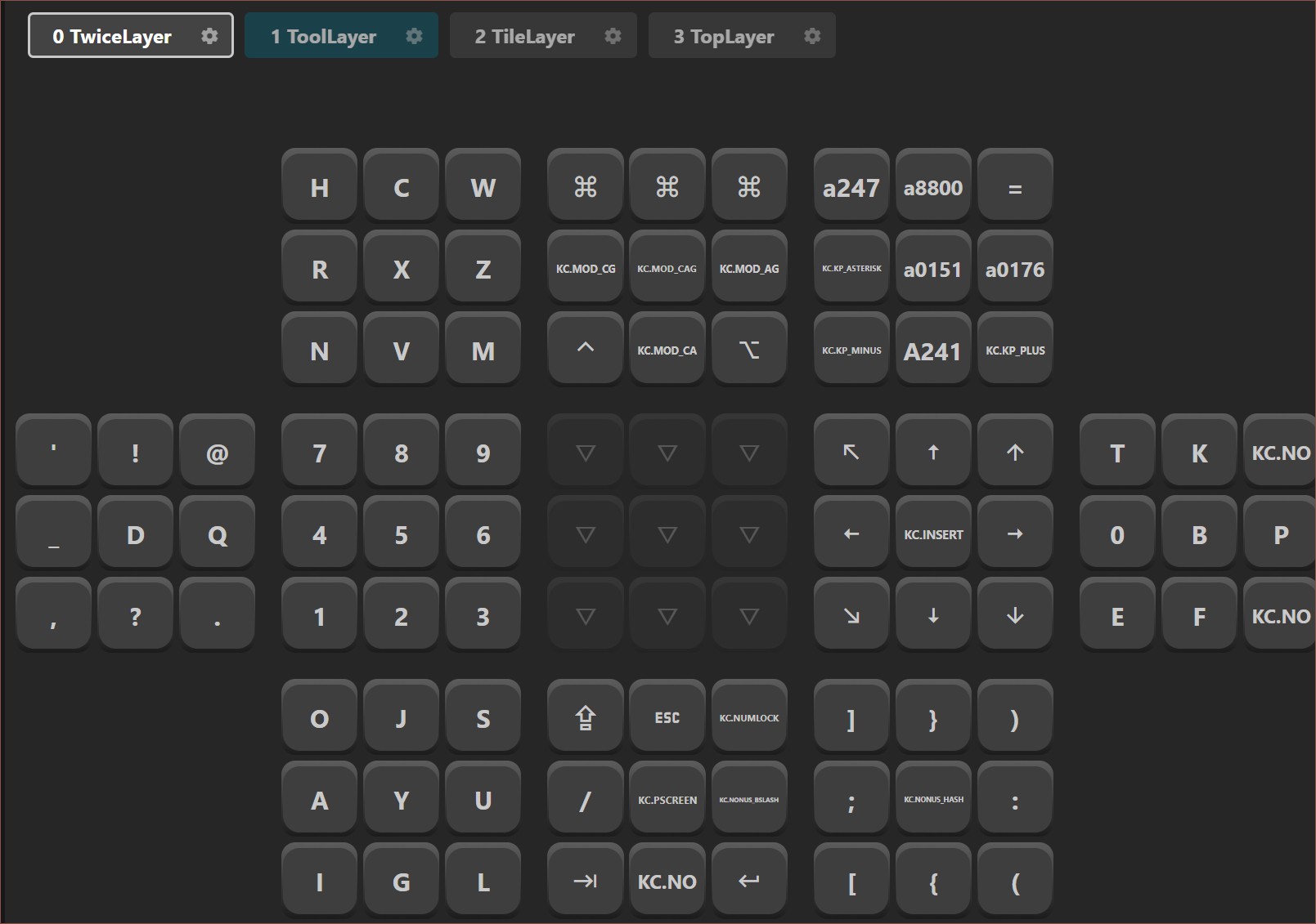
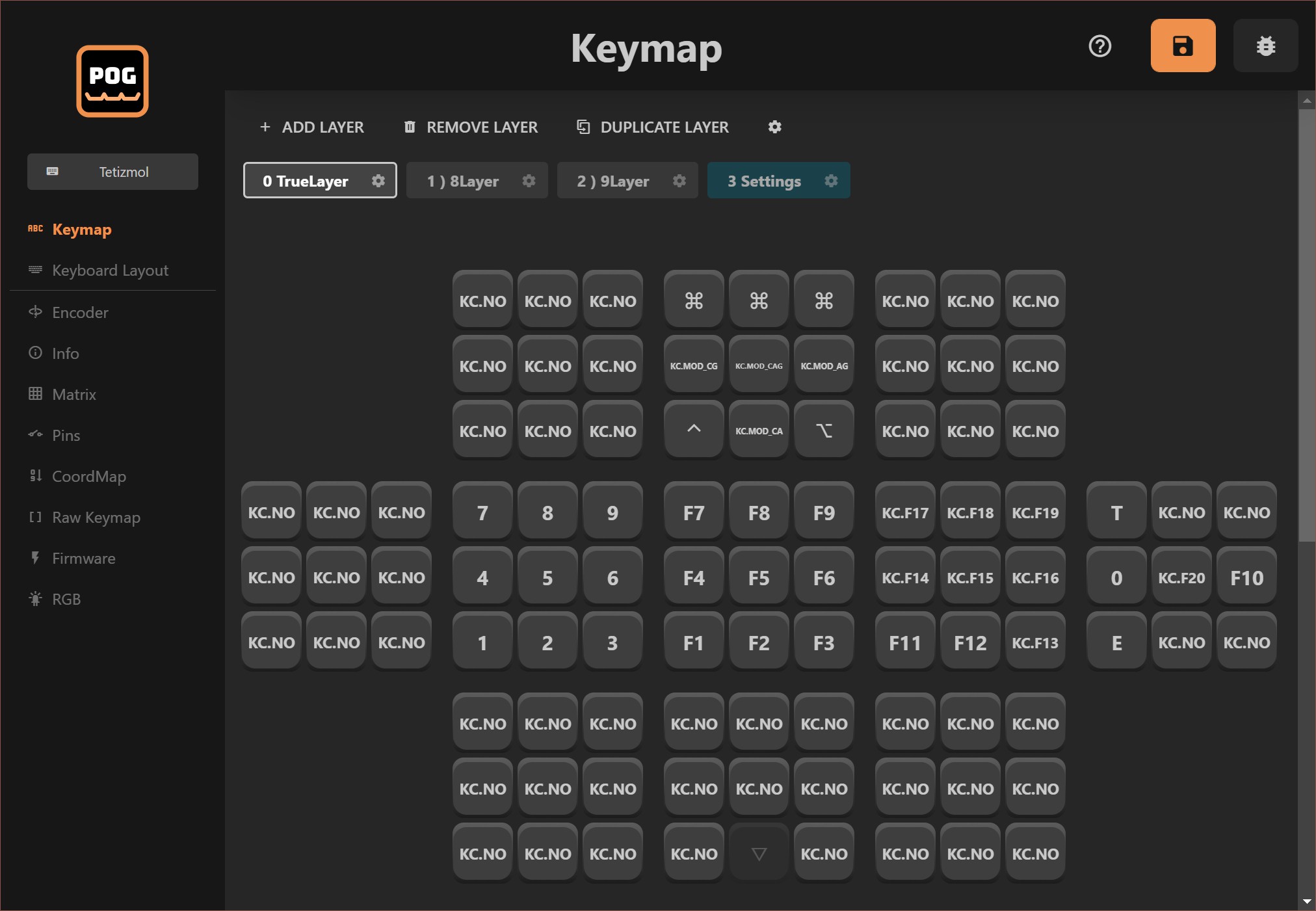
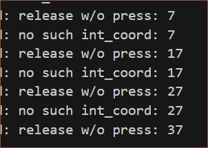
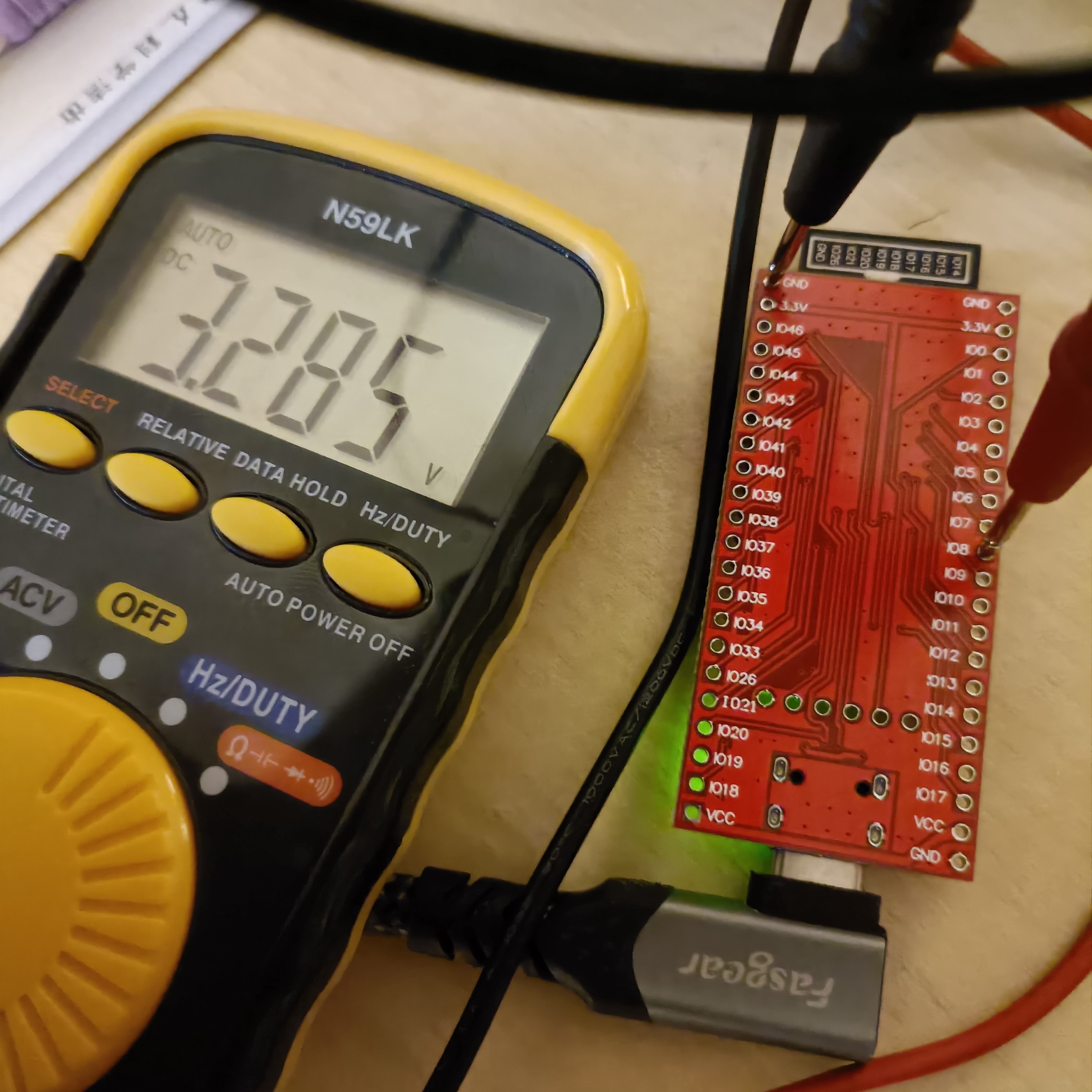
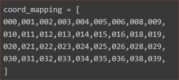
    So I disabled the pins from the map and checked them:

    All other pins were over 3.25, most being 3.28 volts when not in the chord map, and a few mV above 0 otherwise. However, IO38 was precisely 3.202V (when out of the map), so I think there's something wrong with the chip.

    Moving on, I heard pan was fixed so I tested it out and Windows 10 22H2 still complained.

    Unexpectedly, I started getting hit with MemoryError, so I went to compile cpy 8, which was a can of complaints most likely because I didn't do make clear board=[boardname]. I was doing things like deleting the .espressif directory and removing all submodules when WSL unexpectedly folded and the git repo seemed corrupt.

    Still memoryless, which doesn't make much sense as the RP2040 has less RAM but it worked fine.

    RP2040

    So the plan now is to use an RP2040 along with a 16 channel mux:

    A CD74HC4067 breakout board.

    It's probably for the best, since it's got a more linear ADC and more support since it has ARM cores and is the keyboard community's new favourite. For some reason, I had to swap the diode orientation again and it's because it was incorrect till Pog v1.8.2.

    SpaceMouse for KMK

    Here are all the USB HID descriptors that I found:

    1. https://github.com/openantz/antz/wiki/3D-Mouse
    2. https://github.com/ouser555/qmk_spacemouse/blob/main/qmk_firmware/tmk_core/protocol/usb_descriptor.c
    3. https://github.com/AndunHH/spacemouse/blob/main/SpaceNavigator.md
    4. https://github.com/AndunHH/spacemouse/blob/main/spacemouse-keys/SpaceMouseHID.h
    5. https://pastebin.com/GD5mEKW6
    6. https://thingswemake.com/six-degrees-of-syncopation/
    7. https://github.com/joshsucher/six-degrees-of-syncopation/blob/main/spacemouse_pro_emulator/boot.py
    8. https://www.cs.cornell.edu/~curran/articles/space_navigator_quirk/
    9. https://forum.3dconnexion.com/viewtopic.php?t=9827
    10. https://stackoverflow.com/questions/30805483/stm32-usb-hid-reports
    11. https://taoofmac.com/space/blog/2024/05/18/2000

    My main search query in Google was:

    "Usage (Multi-axis Controller)"

    After 3 or so hours, I had understood enough to have an idea on what could be wrong with the AC Pan descriptor, and it worked!

    I decided to use the logical minmax range of 500 instead of the more common 350 since 3DxWare supports values of -512 to +511 (signed 10b int). 

    0x16, 0x0C, 0xFE,  #     Logical Minimum (-500)
    0x26, 0xF4, 0x01,  #     Logical Maximum (500)
    0x36, 0x00, 0x80,  #     Physical Minimum (-32768)
    0x46, 0xFF, 0x7F,  #     Physical Maximum (32767)
    # where 0xF4, 0x01 encodes the 2byte number 0x01F4 (500) for example

    One report floating on the internet has an incorrect comment, as the bits correspond to -32768/32767 respectively:

    0x16, 0x00, 0x80,     #     Logical minimum (-500)
    0x26, 0xff, 0x7f,     #     Logical maximum (500)

    I decided to use the report on newer devices, which have one large report on ID1 instead of a translational and rotational on ID 1 and 2 respectively. It's easier to implement and more likely to be supported for longer. 

    I then went into circuitpython's device.c to pick out the descriptors, as the keyboard, pointer and consumer control descriptors now needed new report IDs.

    I joined...

    Read more »

  • [B][P] 6-core cable and joystick PCBs

    kelvinA02/06/2025 at 15:29 0 comments

    The PS5 joystick PCBs ontop of the 6-core telephone cable

    Most things from the BOM (see below) are going to be delayed due to Lunar New Year celebrations, but 2 components have arrived.

    I was unable to figure out a good way to mount the joysticks without needing the PCB's, so that's why I got them.

    The reason why I got the telephone cable and not some other type of multicore cable is because it was low-cost and each internal wire is single core, which has the following benefits:

    • Easy to strip.
    • No tiny strands to twist and tin to be able to thread them though perfboard.
    • It can hold a bent orientation, making it easier to manipulate.

    As seen below, I was able to use snippers to score the insulation and then use needlenose pliers to pull it off:

    I then measured its dimensions:

    • Outer: 4mm +/- 0.5
    • Inner: 0.85mm +/- 0.07
    • Core: Nominally 0.32mm, thus 28AWG

    It also seems possible to remove the outer insulation with snippers, but I believe a dedicated 50p tool is still worth the investment considering I'd need to do this at least 22 times:

  • [L] Perfboard Circuit

    kelvinA01/25/2025 at 12:07 0 comments

    I was planning to just break and stick stripboard around the place, but I found out about 2x8cm perfboard and found a listing for 5pcs black double-sided for 76p and another for 10pcs green single-sided for 80p:

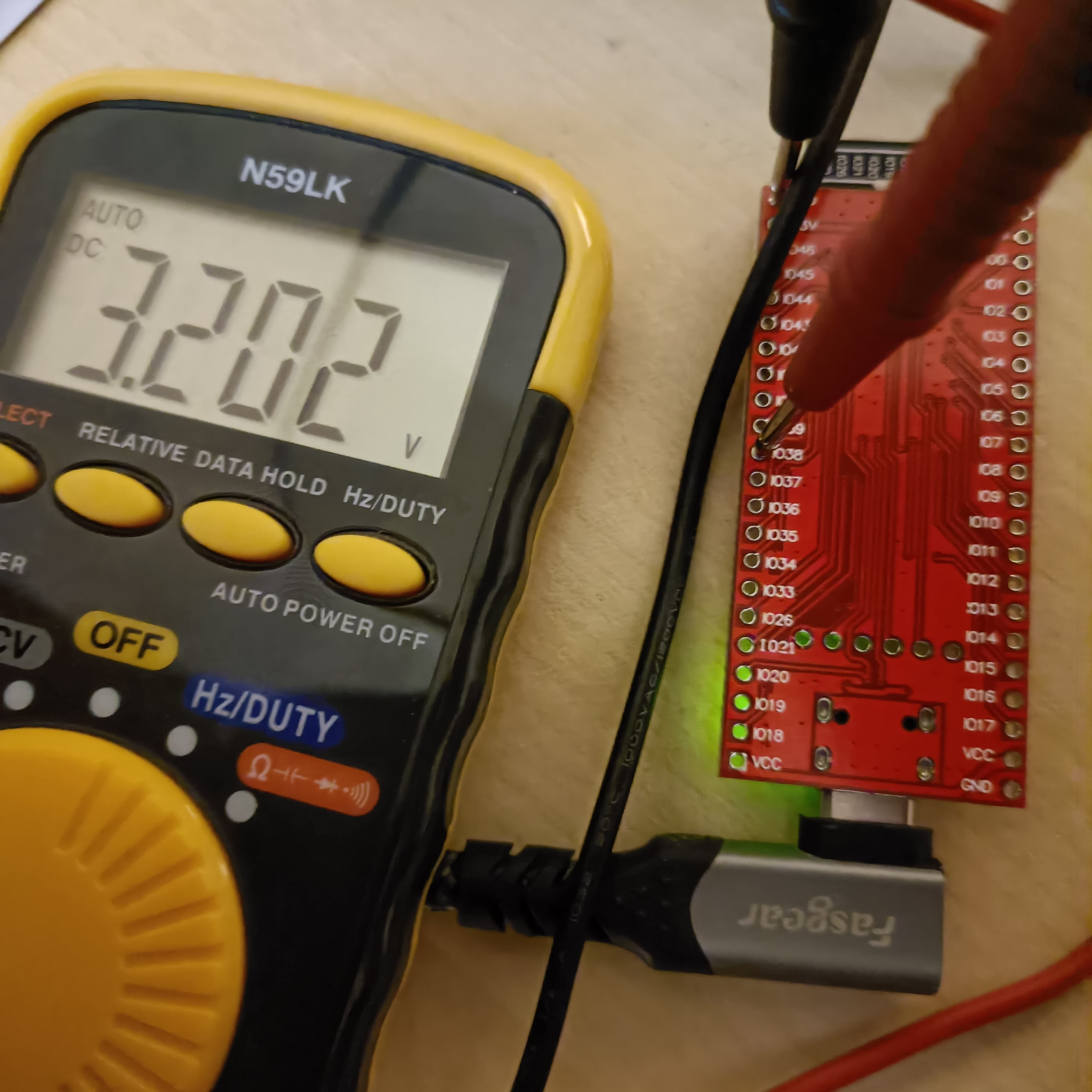
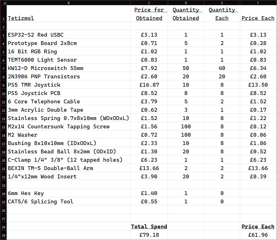
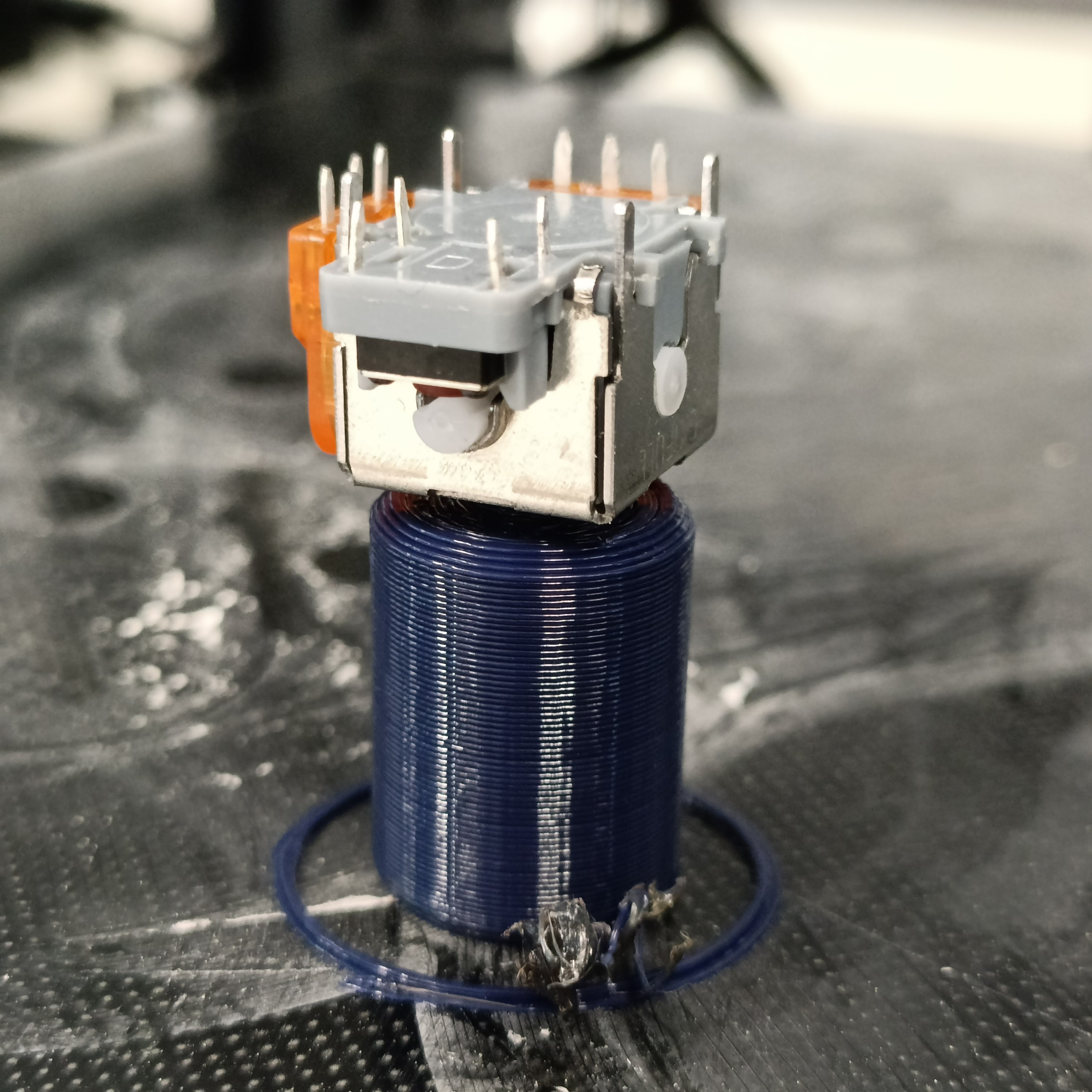
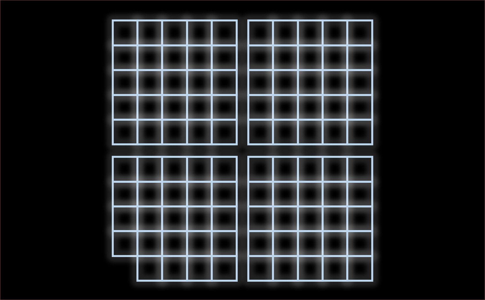
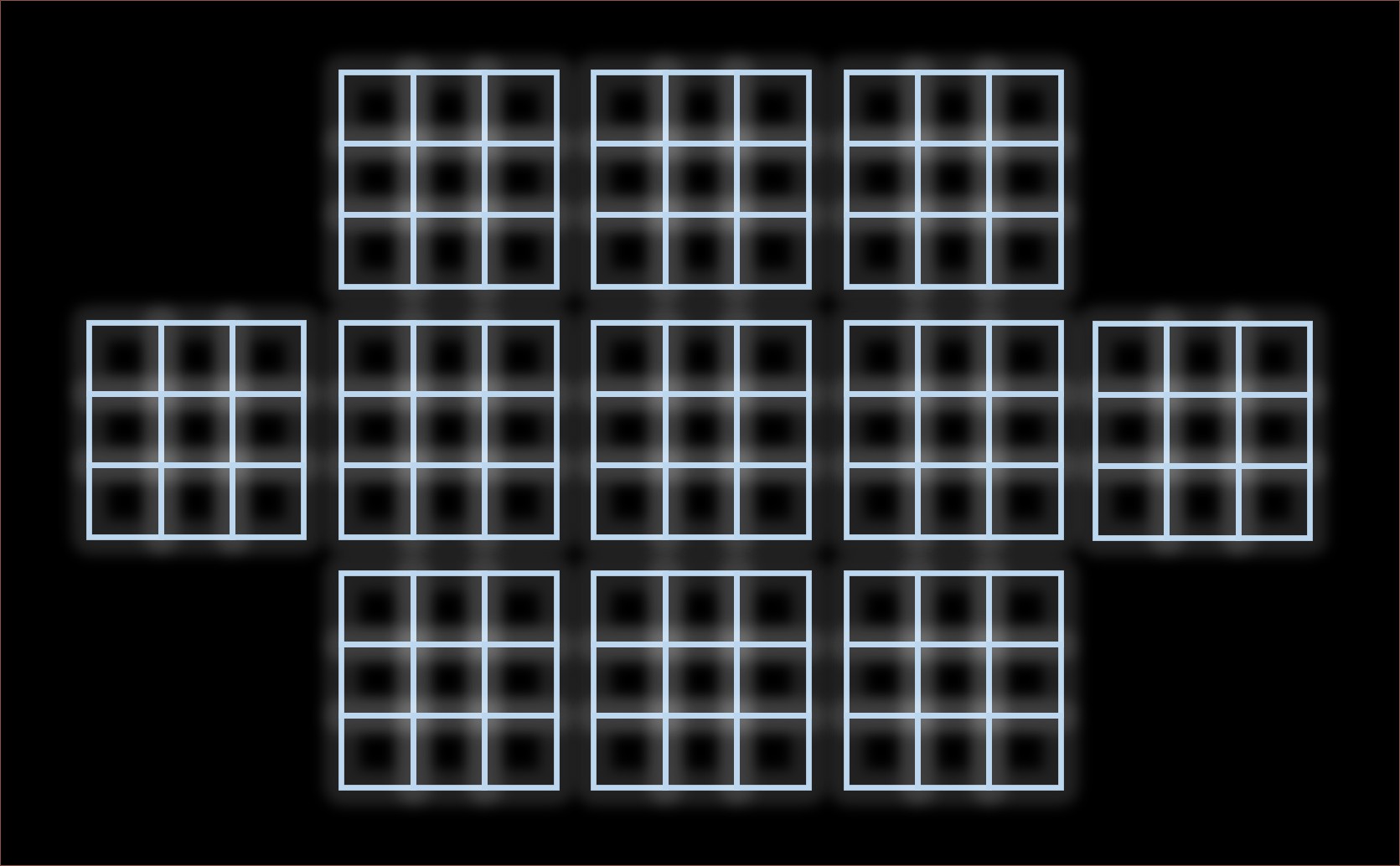
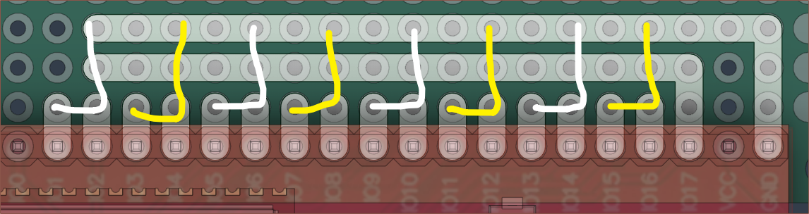
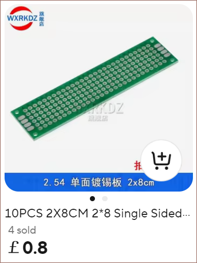
    It just sounds like double sided isn't a need-to-have and would just make desoldering mistakes harder, so I went to design using the single-sided version. After about 4 hours, this is what I've got:
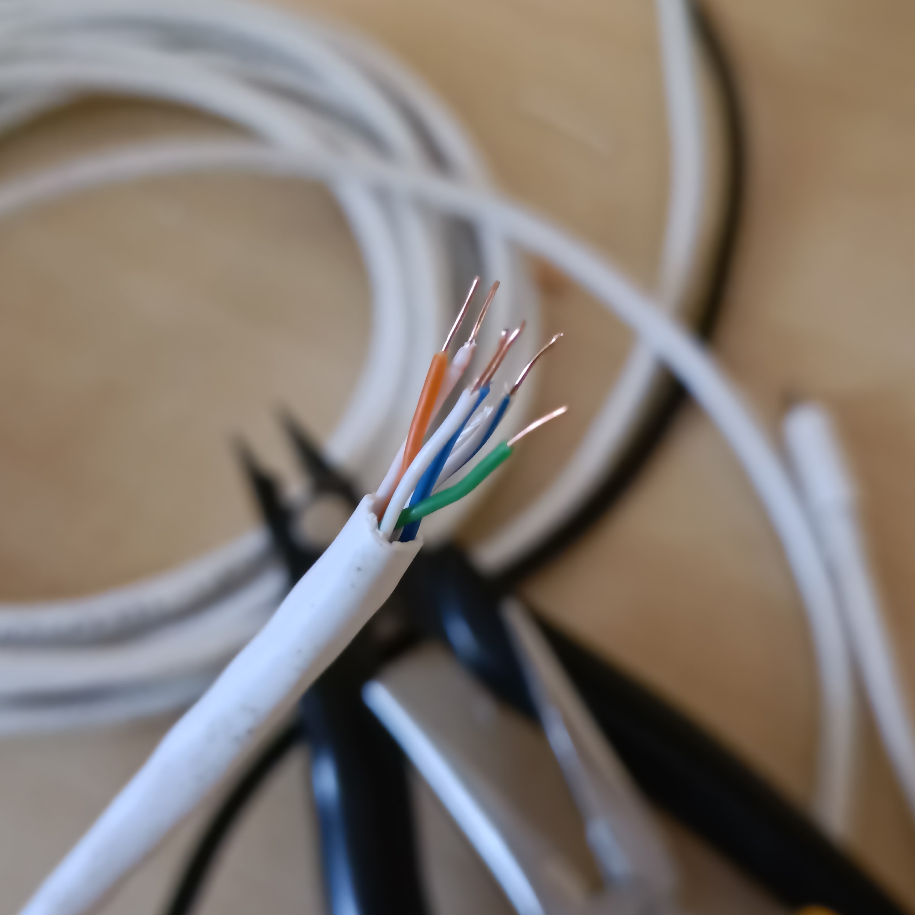
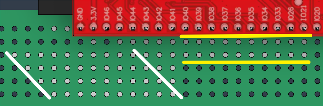
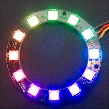
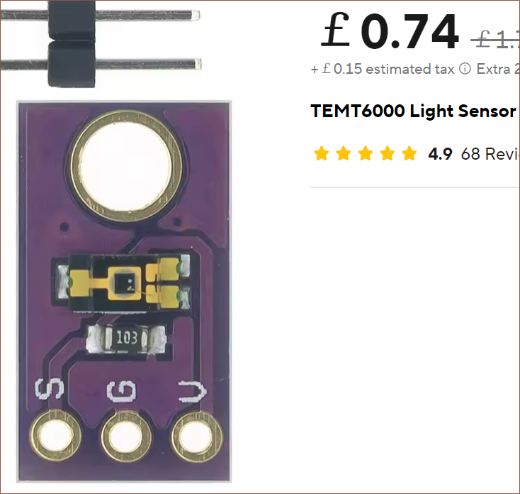
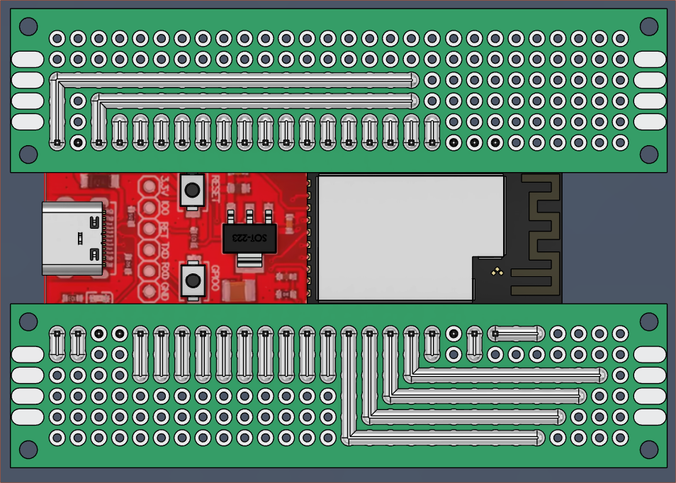
    Before I went to bed, there were also some jumper wires so that I could take GPIO18 and VCC and move them closer to GPIO0 in the pursuit of bundling the RGB ring and luminance sensor in one 6-core cable, but I decided it'll be better to use GPIO45 and just strip some of the wire 50mm longer. GPIO46 is input only, so I assume I can't use it for ARGB data out. I also think the D-in of the WS2812 is high impedance so it hopefully doesn't affect the strapping function of IO45.
    The 6 pins highlighted for the ARGB + ambient light sensor.

    The reason the TEMT6000 is using 3.3V is because Proto Supplies found that the max voltage when VCC=5 was 3.8V. Assuming linearity, with VCC=3.3, I'd expect a 0 - 2.5V output range. 

    Also on this side are the columns and rows, shown in yellow and white respectively. Each "row" is one keywell.

    Moving onto the other perfboard, the 4 pins needed for each of the 8 joysticks is shown below:

    I've alternated the colours so that it's easier to see. Each backwards-L shows the 4 pins needed: X, Y, Vref, GND

    Coincidentally, the mounting holes are M2, same as what I need for the joysticks. Thus, where possible, I'm going to try using self-tapping M2 holes to affix parts together with the M2x14 tapping screws.

  • [E1][R] Component Considerations

    kelvinA01/23/2025 at 21:34 0 comments

    Ginfull joysticks

    I've spent about an hour or two jointing up the joystick assembly so that I can drag the stick and everything moves (as an approximation):

    I've uploaded it to GrabCAD.

    I also talked with a user on Printables who informed me that they preferred the stiffness of a traditional spacemouse. I already had worries that the joysticks might not be stiff enough in the orientation I'm planning, so I started researching into increasing joystick tension. First I measured my SpaceExplorer, which was 300gf. Then I started looking inside the joystick.

    Source: MPE's Ginfull TMR video
    Inside the CAD of the joystick

    One of my first thoughts was to replace the spring with stacked O-rings. there's about 3-4mm of vertical height but, due to that middle cylinder in the base, only a 2mm diameter o-ring or smaller would fit. This would suggest either a 2mm and 1.5mm, 2 sets of 2mm or 2 sets of 1.5mm rings stacked on each other.

    However, I had suspicions that the ESP32-S2 ADC's would be able to detect the much smaller range of motion, so I looked into springs. The spring constant depends on a few factors, and since the original spring is 0.5mm wire diameter and 8.6mm outer diameter, I was able to calculate the expected stiffness increase of an 8mm OD spring with wire diameter of:

    • 0.7mm = approx 3X stiffness increase
    • 0.8mm = approx 5X stiffness increase

    I then found this video showing that the Ginfull Hall Effect joysticks have 60gf of force, which is lower than the standard of 80gf.

    This would mean that 0.7mm = 180gf and 0.8mm = 300gf. After much hopping back and forth, I've decided that using 0.7mm springs are more likely to work, or perhaps I should say that both share the same list of "reasons it might fail" but 0.8mm has additional reasons. One of them is that a 5X increase might be too much for the components in the joystick to handle.

    I'm not entirely sure if 9mm OD springs will fit, but I get twice as many 8mm OD for the same price.

    12 bit LED ring and ambient light sensor

    My original idea for lighting was to have LEDs inside the keywells and they'd glow like a sci-fi prop. However, I thought it would be more useful to have some sort of "display" instead. 

    With a 12b ring, 5 LEDs could be on the left/right and shine a different colour depending on the chord of its respective keywell. This would act as a display for my peripheral vision, should be visible in daylight and allows brighter LEDs without drawing too much current from the host. I've also got ideas for sci-fi-esque animations, like a slow loading circle when it's idle.

    Since Tetizmol is likely to be used in a range of ambient conditions (sunny day to midnight coding) and I remember just how eye-stabbing the bright LEDs under the WK-50 encoder were to my peripheral vision, I'm going to try connecting the LED ring to one of the strapping pins so that the above TEMT6000 light sensor can be read via GPIO18. Another idea is to put this sensor on GPIO17, along with all rest of the ADC-in pins, and use GPIO18 as DAC-out.

    1/4-20 Wood Inserts

    I've never been keen on heat inserts since I need to use my soldering iron to insert them and make sure they're straight. One day, I found out that the Charachorder CC2 CAD files were on Github and so I was able to see the insert they used:

    Well these ones specifically seem to only be available as a pack of 50 for £8 on AliExpress. However, I found these zinc wood inserts:

    I wasn't too sure about them, but I then found this video:

    A commentor mentioned that having the flange on the rear side of the intended thread is the strongest configuration, unlike what was tested in the video (for both rivets and these zinc wood inserts).

    It turns out that I have every allen key size except 6mm, so I've put that in my basket too.

    Super clamps and magic arms

    Ignoring that the names of these products sound like Superman V Dr Strange, the mounting solution is...

    Read more »

  • [E1][R] Hall / TMR joystick electrical properties

    kelvinA01/13/2025 at 21:25 0 comments

    I almost lost hope that I'd find out some electrical information for the hall effect joysticks, but then I found an oasis of information: Metal Plastic Electronics (which I'll abbreviate to MPE). 

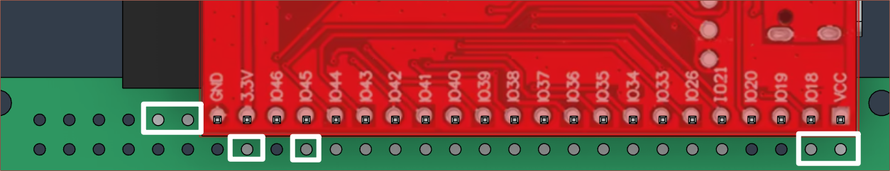
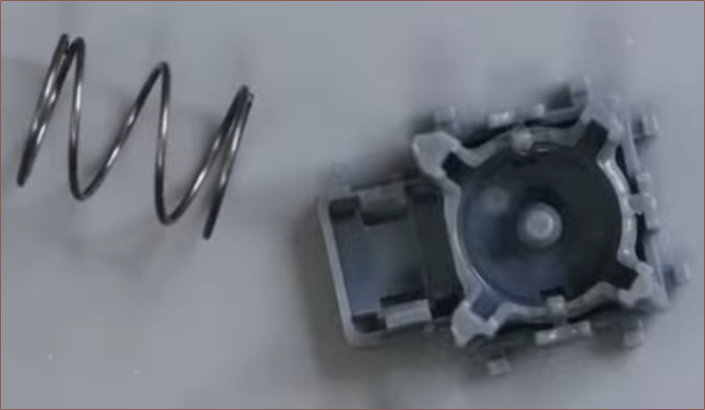
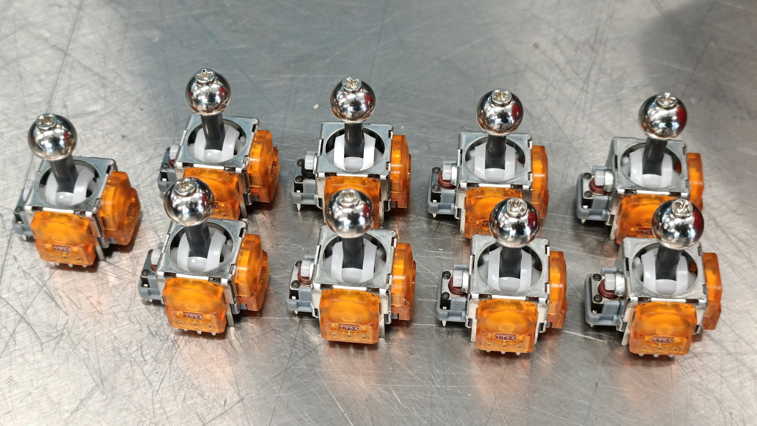
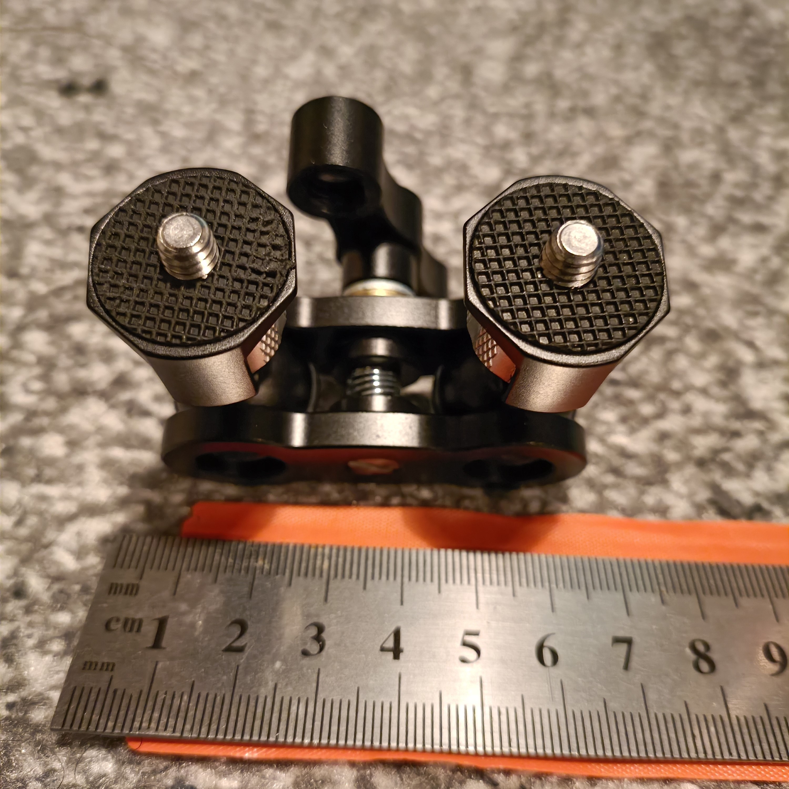
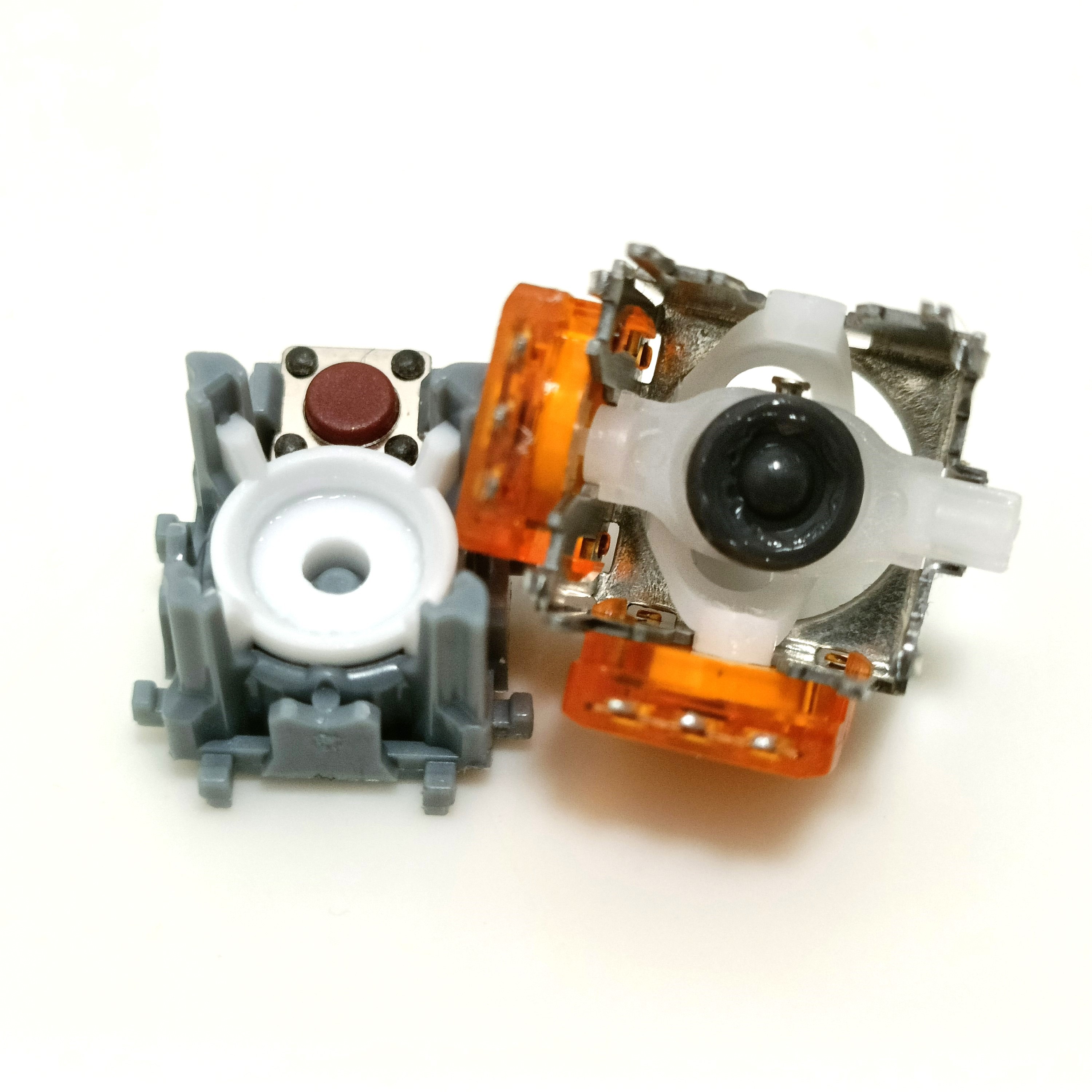
    It's a channel that has dug for details on many of the electromagnetic joysticks on the market! This log kind of serves as a TL;DW. I'll try and speedrun though the things I learned watching his tests yesterday, starting with a video where he tests these:

    The rise/fall time of yellow (Ginfull) sticks are unbalanced

    The one I found on ebay are the L4A sticks:

    Yellow is the current of the electromagnet.
    As it turns out, a capacitor is on the output pin meaning that it has to discharge when the signal voltage is lower than it. This results in fast rise times but very slow fall times. In a comment, MPE tried using pulldowns to no avail.

    This might not be too noticeable when orbiting around in spacemouse mode, but it's going to lead to overshooting if used as a trackpoint. 

    As you can see, the magenta trace is a (not so traditional) potentiometer stick and cyan is Ginfull hall sticks. MPE manually moves both sticks to and fro.

    The rise/fall of the blue and green sticks are fast and symmetric

    Blue sticks
    Green sticks

    The green sticks use a larger magnet, so it seems they'd be less susceptible to stray magnetic fields than the others. The drawback for this application is that the sticks don't have a cylindrical hole, meaning I can't screw in a ball to the end of it:

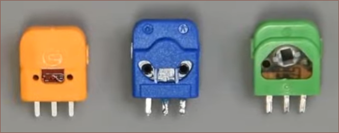
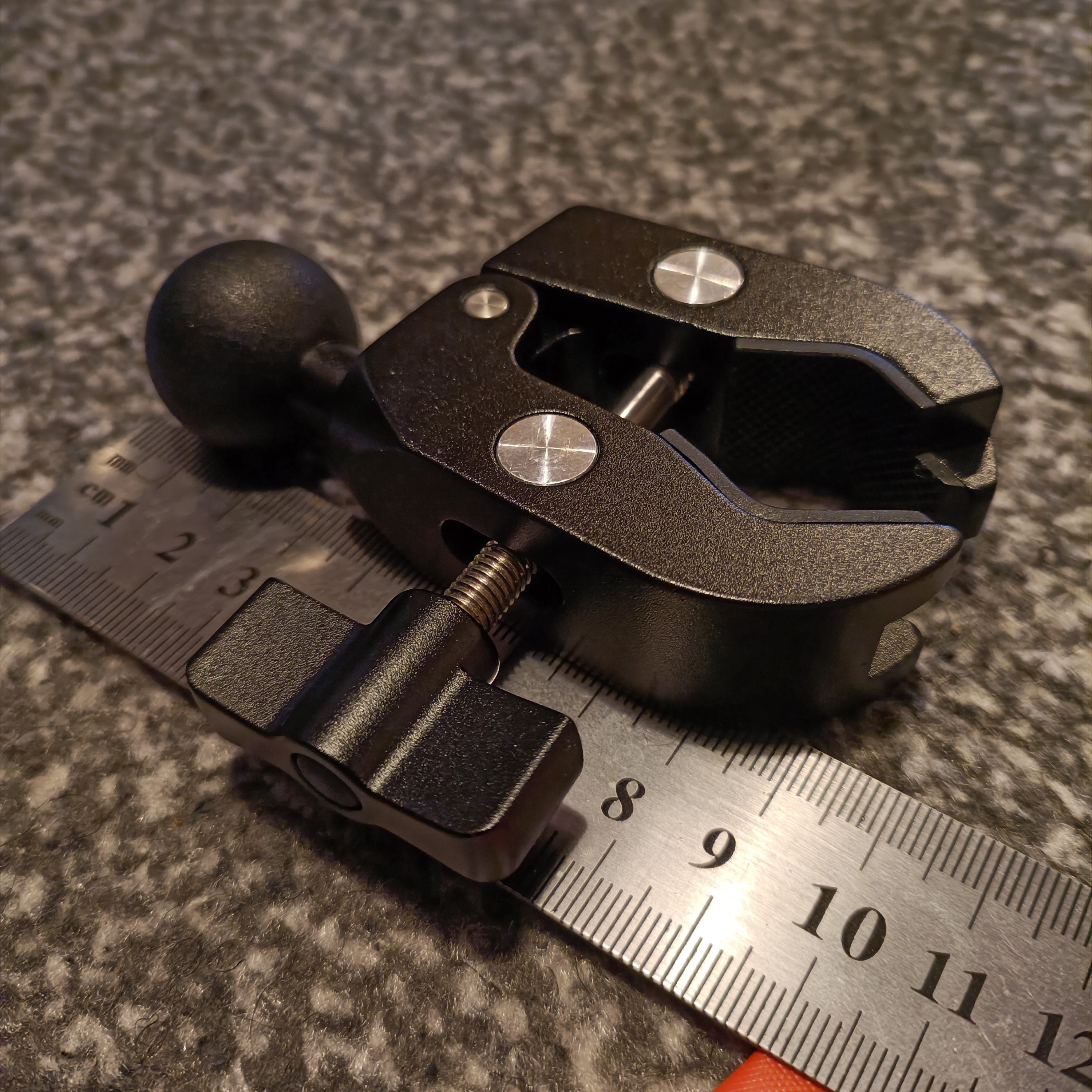
    The blues/greens are similar in price.

    The sticks likely accept 1.6 - 5.5V

    The chip inside the Ginfull hall effect sensors is rumoured to be the Hallwee HAL9303, which has the following voltage ratings:

    • 1.6V Min
    • 3.3V Typ
    • 5.5V Max
    • 7V Abs Max

    MPE used 1.8V in his testing.

    TMR sticks use low power to output a signal that closely matches the magnetic field

    For example, here are the Hallpi TMR joysticks, which are about 2X the price of the average hall joystick:

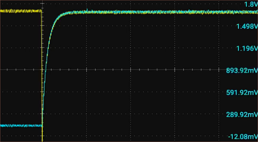
    There were also the blue K-Silvers (cheapest) and black GuliKit on his channel.

    TMR sensors seem to pull around 210uA of current, compared to 700uA for the Ginfull L4B board (which was found to be identical to the L4A board).

    Ginfull TMR recently arrived on the market?

    So I was thinking that I was going to get the blue joysticks below:

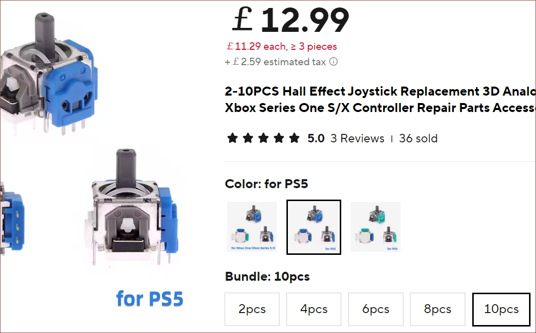
    But I also noticed some translucent Ginfull TMR sticks:
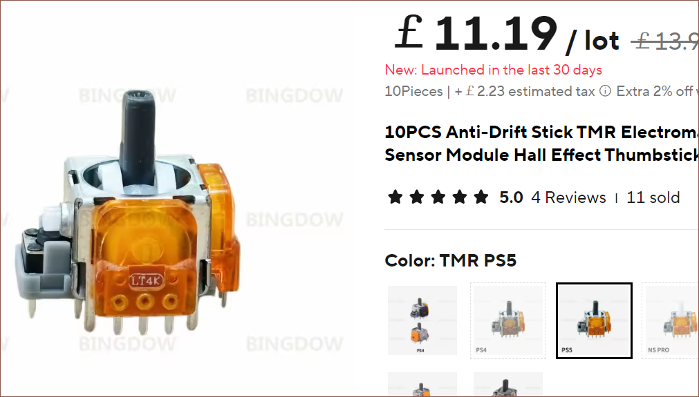
    I found another listing where the price difference between the two options would be pennies, both effectively being £16 including shipping and VAT. 

    If these were like the other Ginfulls, I'd have to skip them. If they were like the other TMR brands, it's an easy win. One of the only references I could find was a 15-day-old post on reddit and 2-week-old comments under the Hallpi video with MPE replying that he had them on order. 

    Thus, I went to bed hoping that the video would come out in the near future.

    The TMR future is now!

    MPE published a video of them today:

    MPE taking a close up shot of the new Ginfull TMR sensor.

    They share similar components to earlier hall-stick designs, but they have all the benefits of TMR with none of the filtered output:

    Ginfull TMR: Rise
    Ginfull TMR: Fall

    The current draw is typically around 215uA, up to 375uA if the chip is outputting VCC (1.8V in his testing). 

    [Edit 1] MPE also heard from another commenter that the chips inside the TMR joystick may be the TMR2615x-AAC.

View all 18 project logs

Enjoy this project?

Share

Discussions

Morgan Venable wrote 11/28/2024 at 15:21 point

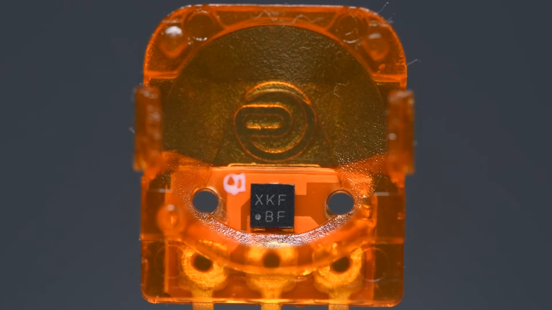
Fun hack!  The height seems like kind of a challenge, but I love anything that explores the frontier of what's possible with unusual finger and key configurations.  

Do you have any pics of how you envision this in use?  I've messed around with more N/S split key orientations on Svalboard prototypes, but haven't convinced myself of sufficient dexterity in the ring and pinkies especially -- the lateral movements on DH/Sval are not so difficult, as they're aided by wrist mobility and some specialized nuances of fit as well.

Anyway, super interested to see how this shapes up for you.  Nails are a challenge in so many different input contexts -- nails vs capacitive touch can be a real struggle!

  Are you sure? yes | no

kelvinA wrote 11/28/2024 at 15:46 point

"nails vs capacitive touch can be a real struggle" - Completely agree. I will say that I have tried conductive, thin finger sleeves for mobile gamers, upgrading the nail into a rather nice stylus. I'm waiting for a thin glove of the same material so it's faster to (un)equip.

My second log is going to be on how I envision using this with the chorded layout, but the general idea is a grip similar to a vertical mouse with 2 switches on the nail and fingerprint sides respectively. 

The microswitch lever length is mainly to reduce actuation forces to something manageable for chording, but I have seen some sub 30gf microswitches on Digikey.

  Are you sure? yes | no

Does this project spark your interest?

Become a member to follow this project and never miss any updates