 kelvinA
As discovered in #WK-50 Trackball Keyboard, allegedly a keyboard designer could use PNP transistors as a "dual diode" package. If this works, it would be useful as I won't need to worry about diode polarity and will only have to "starter solder" half as many components (whereby starter solder means having a component that isn't held in place by a solder joint yet).
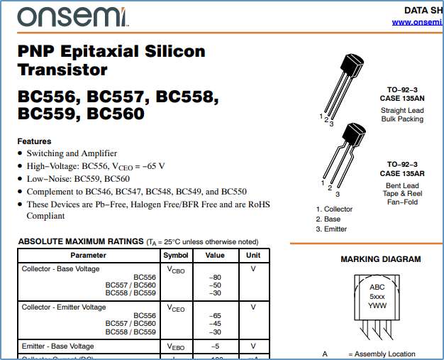
I went to my uni and they happened to have some ZTX502 PNP that mouser said was discontinued so I looked on ebay and it seems that the 2N3906 is the cheapest and most abundant:
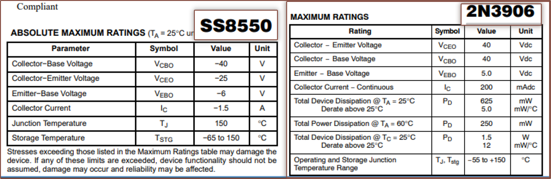 I did some looking into it and, from my understanding, I don't think that there would be any differences that should matter for this application. Hence I went back and the uni happened to have some 2N3906's that I proceeded to solder on:
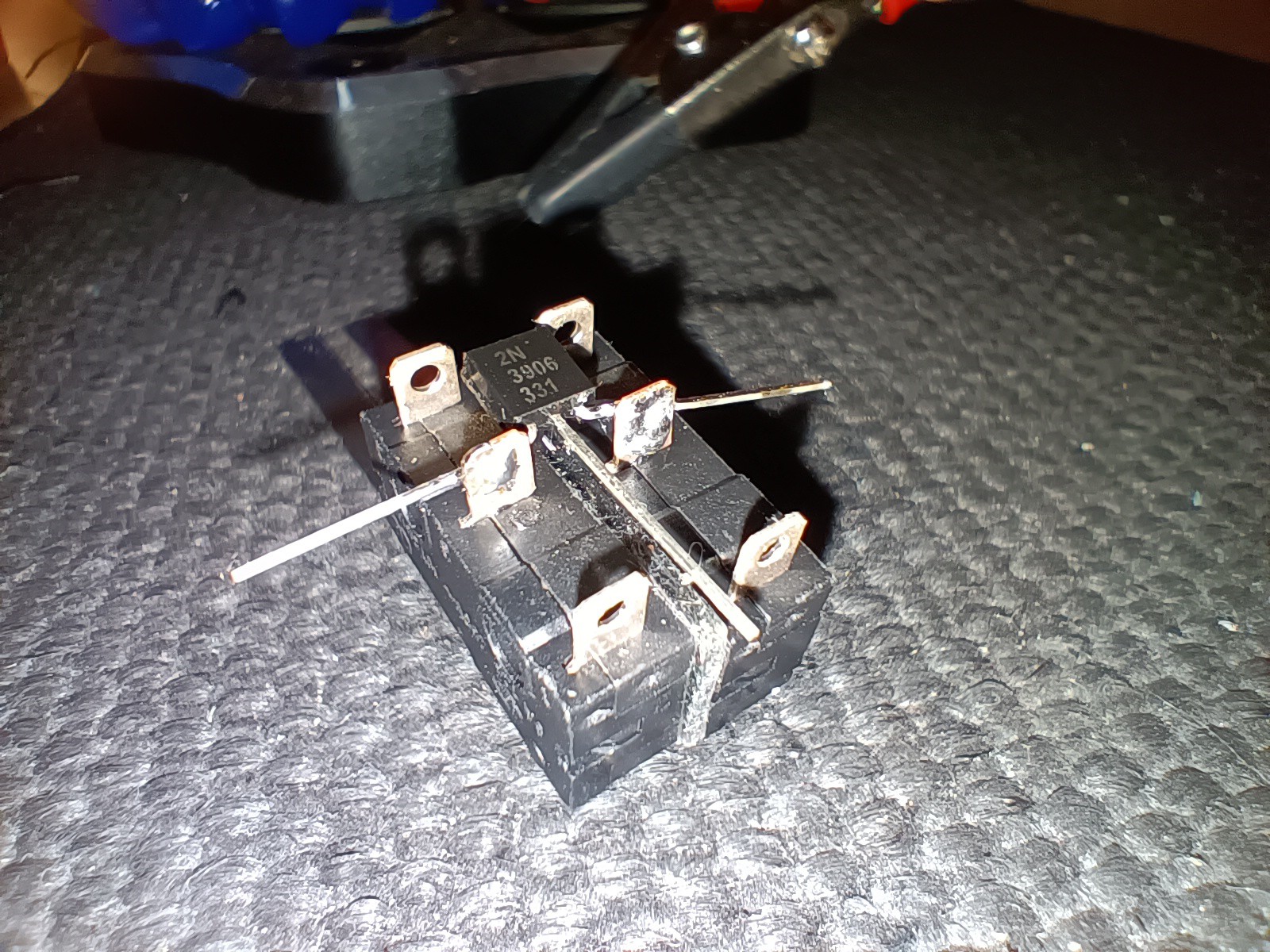
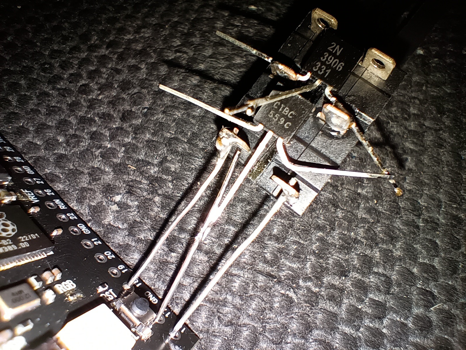
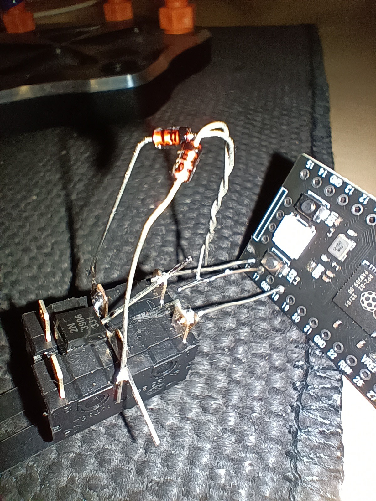
For my First Attempt In Learning (FAIL) how to best solder the transistor on, I think it already looks rather good. Now I know:
- not to try and solder with the iron on the opposite side, because the molten solder will be sucked in.
- text facing up so that the pins are as far away from the switch enclosure as possible
- orient like above so that the wiring can be 3 easy pins, as seen below.
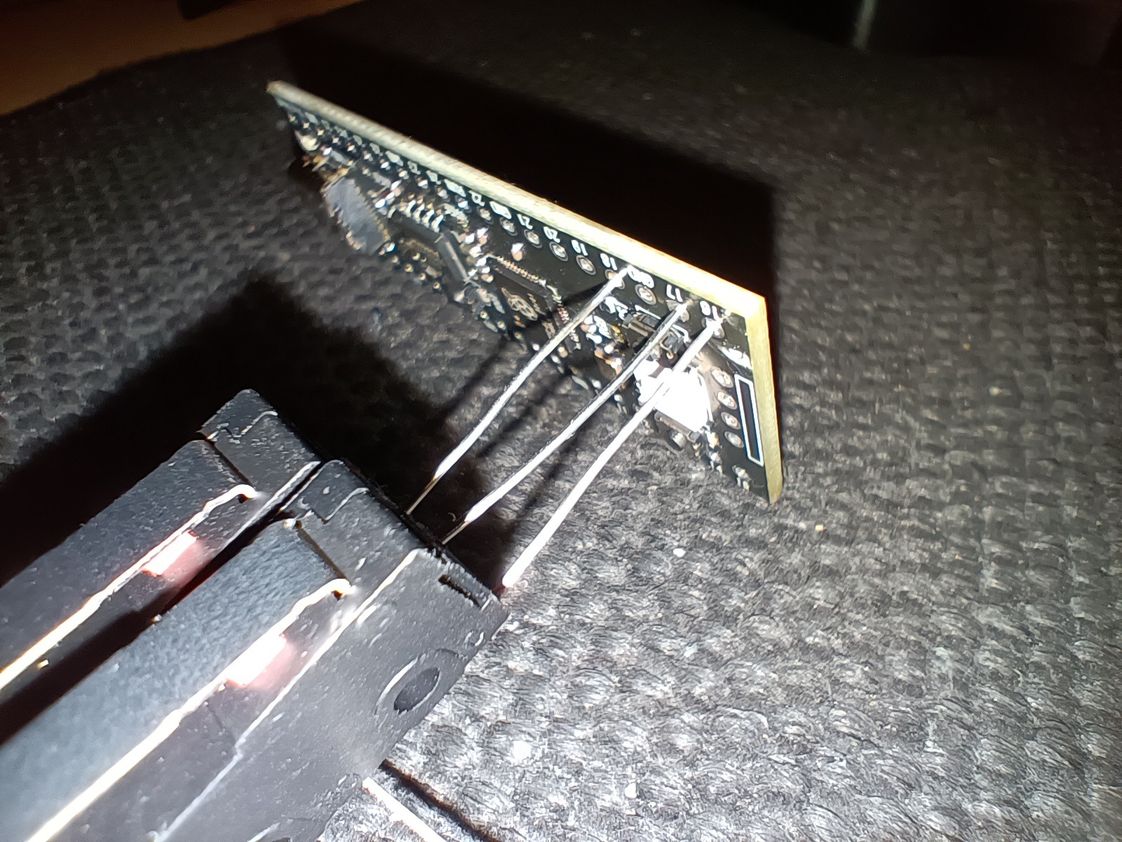
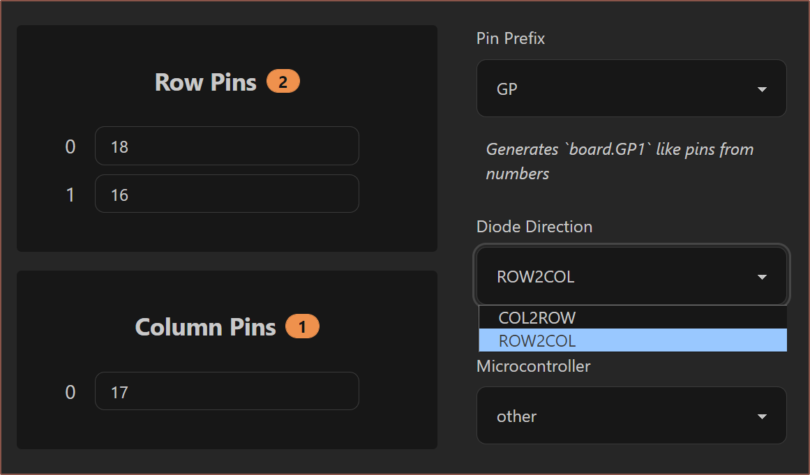
I checked continuities and then I installed KMK/Pog and changed the diode direction to ROW2COL, since the "diodes" should be pointing towards the column, but I wasn't getting anything when pressing buttons but was when I manually shorted them, so I know my pins are correct:
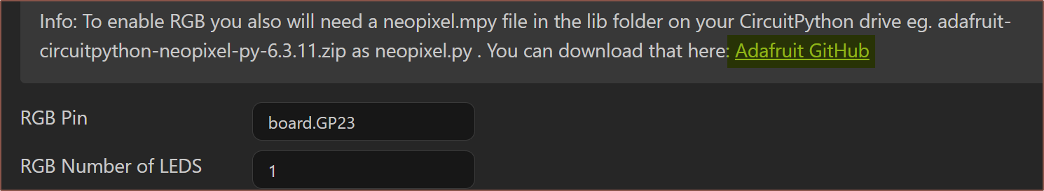
I also learned how to use the diode mode on my multimeter and I was getting .685 and .680 when the red lead was on pins 1 or 3 and black on pin 2, with 0L for anything else, so I know they're essentially acting like diodes. I did manage to get the neopixel working though by adding the neopixel.mpy into the lib folder and using GPIO23:
So I tacked it on:
And the chordmap still didn't work. But now it also wasn't working for shorting pins so I closed Pog and decided to go into the serial port.
I had a card up my sleeve. I had also asked for 2 diodes which obviously should work. Their voltage drops were .546 / .562V when I soldered them on:
And as expected... wait, no! It's still not working!
 Opened Pog again to check settings, changed the diode orientation to COL2ROW and saved:
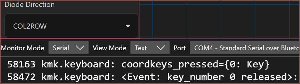 So now I have a configuration I know works, so I desoldered the diodes and soldered the 3rd pin for the 2N3906:
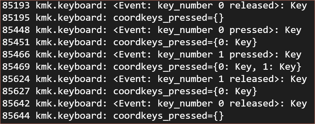
So now it works????
Not entirely sure what happened. The voltage drops are .687/.682 so it's not like the transistor has changed much. I can only assume that maybe Pog didn't save or maybe the chordmap finder isn't as reliable as I assumed for testing keys.
Discussions
Become a Hackaday.io Member
Create an account to leave a comment. Already have an account? Log In.