On market there are lots of options for sound card-based data modems, like Signalink, Digirig and lots of DIY and cheap modems. I haven’t seen any Bluetooth based audio data modem apart from Mobilinkd which is unfortunately Bluetooth serial port TNC.
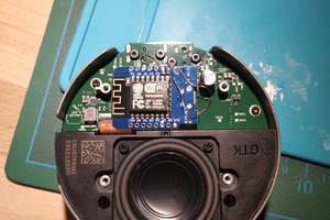
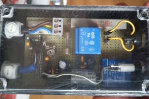
In order to keep the cost to minimum I got together components I already had just had to order the microcontroller as I didn’t had any small form factor microcontroller. One reason for the project internal looks so crude.
I’ll be working on a proper PCB design but as I don’t have any experience designing surface mounted level PCB will be looking for some expert help. Might switch SMD to Through hole components.
Blew is the basic circuit which I had in mind but many changes were made wile making the modem.

Power:
Initially, I had planed to use 3.7V BMS to charge the battery and was hoping it would have internal 5V DC boost circuit. but I had to switch to a old power bank BMS circuit with modified USB C board. I had to solder a push button in parallel with BMS push button. Out put had a STSP slider switch to cut off the power to the rest of the circuit.
Power out from the switch was solder to a PCB patch to serve as Power bus to connect rest of the components power.
BT002 Bluetooth Module:
BT002 Bluetooth module is a cheap module with audio in/out and few other controls. I only used +5V, Ground, Mic, Audio Left, Audio Right.


Microcontroller:
I had to order a small form factor microcontroller, I went with Chinese Microcontroller “Pro Micro” It can be programmed in Arduino IDE as Arduino Leonardo. I needed only 2 pins 1 as input and 1 as out put, in future I’ll add a 10K Potentiometer to add programable PTT trigger delay. right now it is done while programming the microcontroller.
*No External LED was used as displayed in the circuit above.

Relay module:
I went with relay based PTT for few reasons, not all radios like Transistor/ Mosfet based PTT. Using Relay based PTT make it much simple. I used CW-025 5VDC Relay module.

Modem to Radio connection:
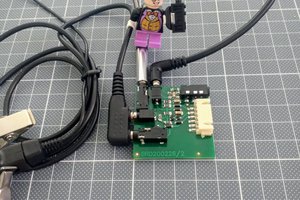
To keep all simple I used RJ-45 Port to connect Radio to Modem. It easy to make RJ-45 based cables then using any special connector.

Audio I/O and PTT:
For Audio I/O from bluetooth and radio I used following configuration:
Blutooth Audio Left goes to radio mic via 10uF capacitor.
-Bluetooth Audio Left goes to Radio mic input via 10uF capacitor.
-Bluetooth Audio right goes to Pro Micro using Voltage divider via 10uf capaitor.
-Bluetooh Mic in is connected to Radio’s audio out via 10uF capacitor.
Pro Micro Code:
simple code is written in Arduino IDE. Audio level is monitors on analogue input pin. Once the audio level meets the threshold PTT is triggered. I added 1 second delay after the audio goes below threshold before the PTT switched off.
Code:
// Blue Dmod //
// https://uhpowerup.com/ //
// Author: 2E0UMR //
// use at your own risk //

const int audioPin = A1;  // Audio input pin
const int RPin = A3;     // Relay pin
const int threshold = 200;  // Adjust based on your audio signal

bool RState = false;      // Tracks Relay state
unsigned long offTimer = 0; // Tracks time to turn off the Relay
const int offDelay = 1000;  // 3-second delay in milliseconds

void setup() {  pinMode(RPin, OUTPUT);
Serial.begin(9600);
}

void loop()
{  int audioValue = analogRead(audioPin);  // Read audio signal
Serial.println(audioValue);            // Debugging: Print the value
  if (audioValue > threshold) {          // Audio signal exceeds threshold
digitalWrite(RPin, HIGH);          // Turn Relay on immediately
RState = true;                     // Update Relay state
offTimer = 0;                        // Reset off timer  }
else if (RState && offTimer == 0) { // Start the 3-second timer
offTimer = millis();                 // Record the current time  }
  if (RState && offTimer > 0 && millis() - offTimer >= offDelay)
{    digitalWrite(RPin, LOW);           // Turn Relay off after 3 seconds
RState = false;                    // Update Relay state
offTimer = 0;                        // Reset off timer  }
}
I have tested the “Blue...
Read more » uhpowerup
 erv.plecter

 Christoph Tack
 Entunassa