Arnov Sharma
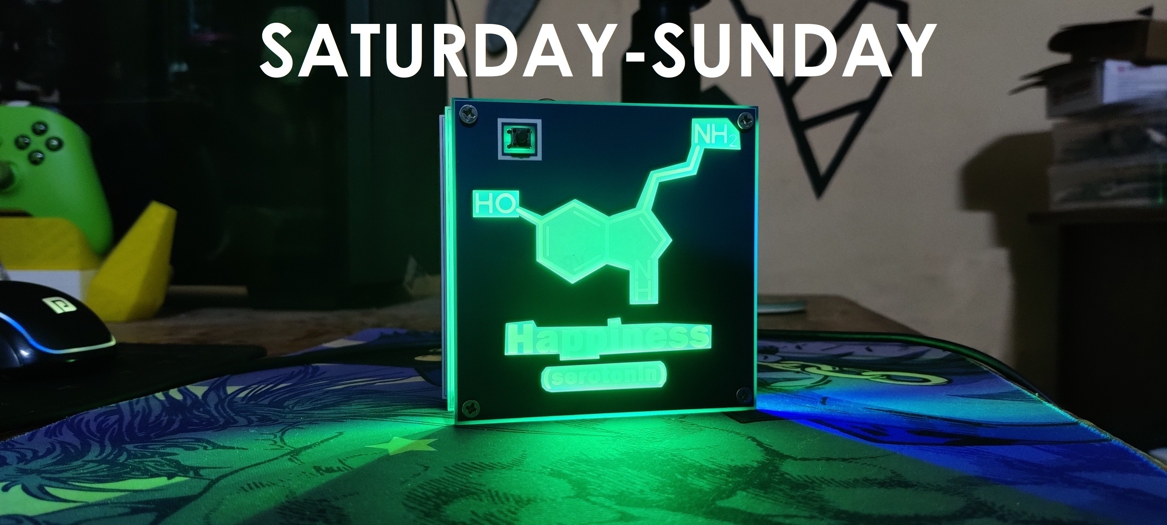
In order to keep track of the day and control the WS2812B LEDs, we are utilizing Seeed's XIAO ESP32 C3 microcontroller board, which is connected to the internet.
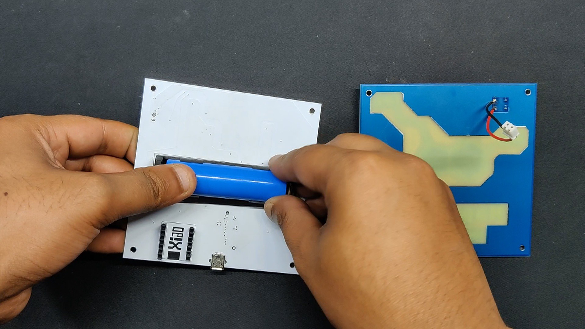
Three PCBs in all were layered together using PCB standoffs to create a sandwich-like framework for this project, which was entirely composed of PCBs. The microcontroller setup, power circuit, and WS2812B LED array are located in the middle layer. The front PCB has an appealing graphic and a power button, and the back PCB is merely there to cover the device from the back because it has an exposed lithium cell and microcontroller board.
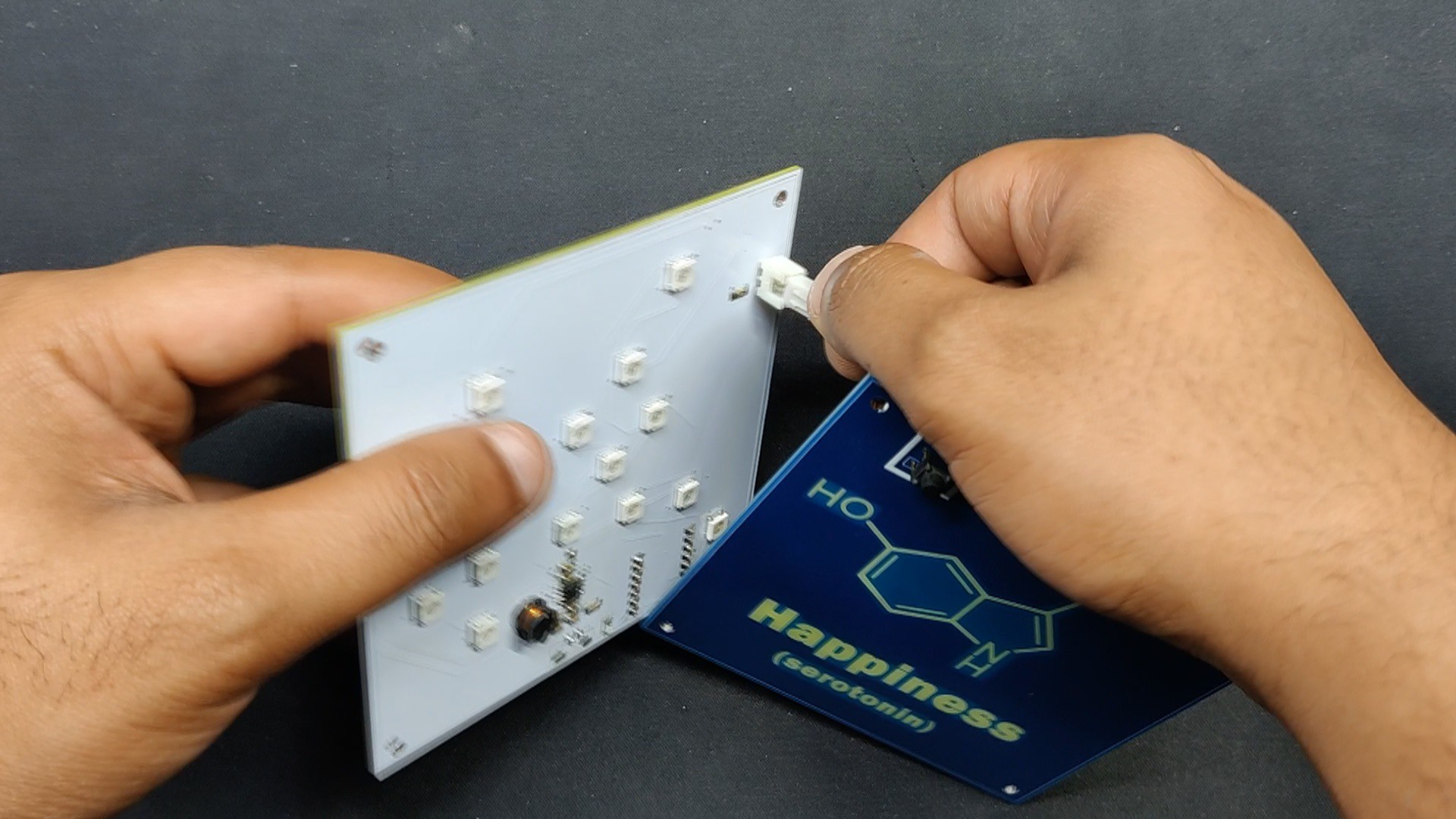
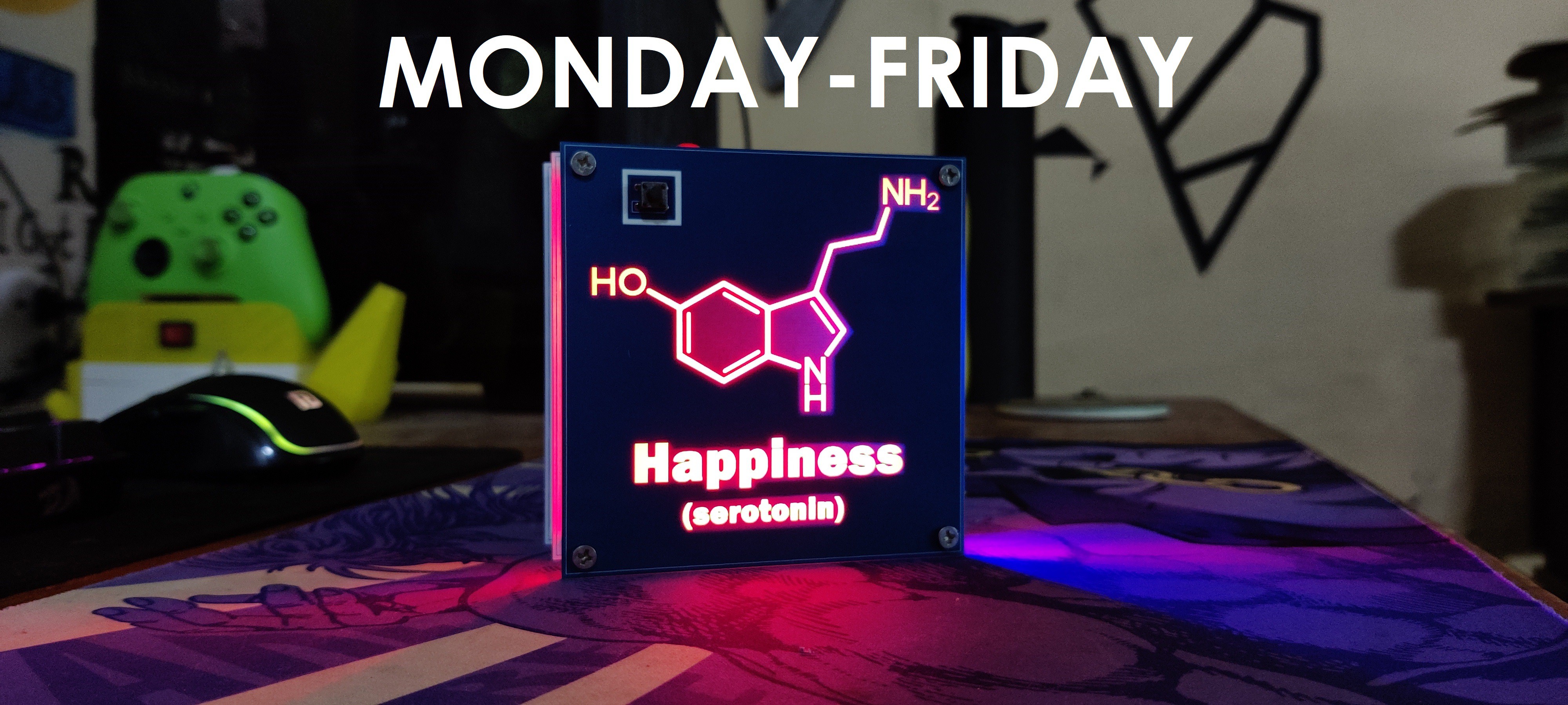
We added a front PCB layer with the chemical structure of serotonin, also known as the happy hormone, to turn this project into a work of art.
This article is about the whole construction process of this project; let's get started with the build.
Circuit

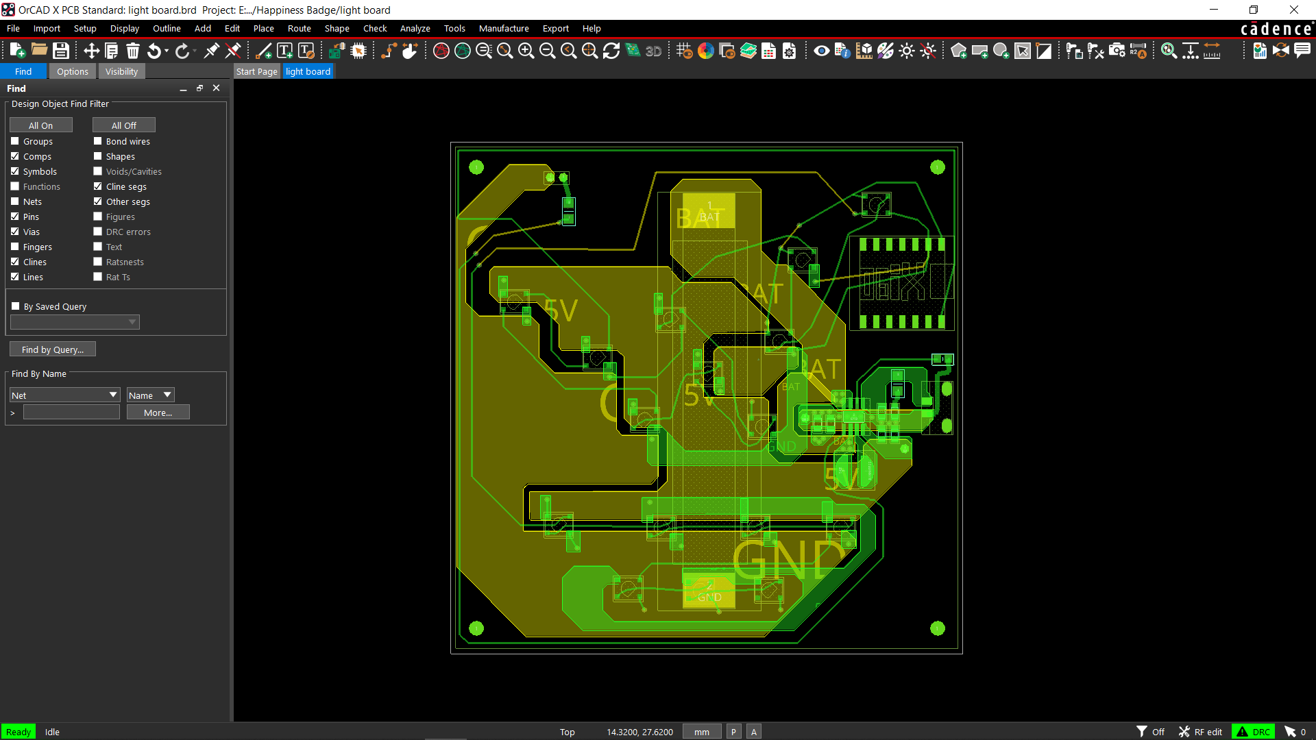

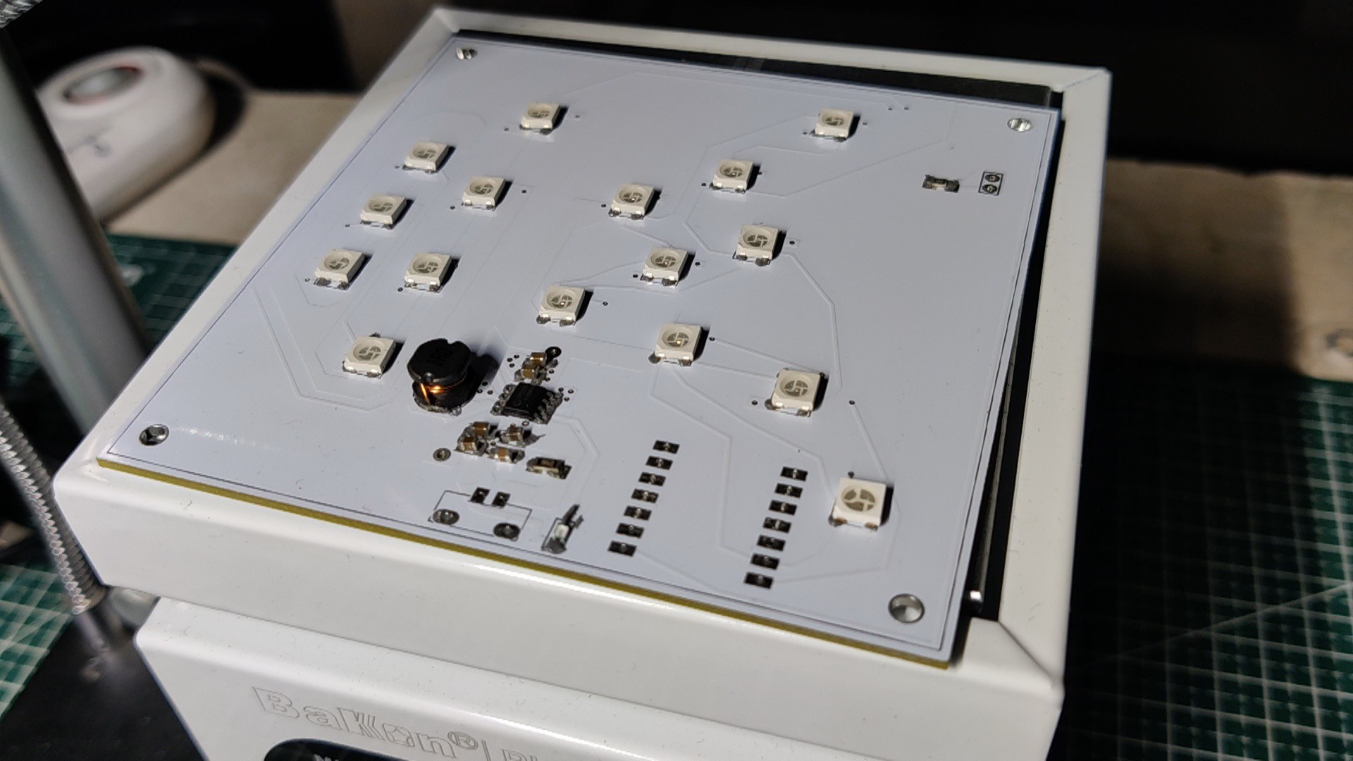
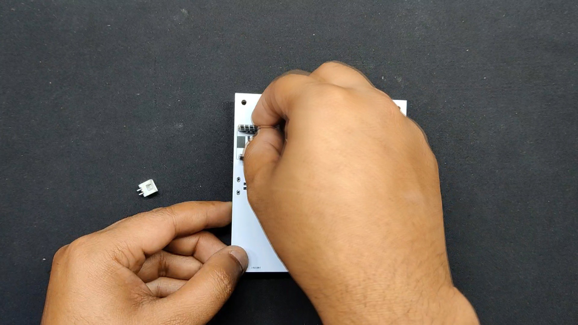
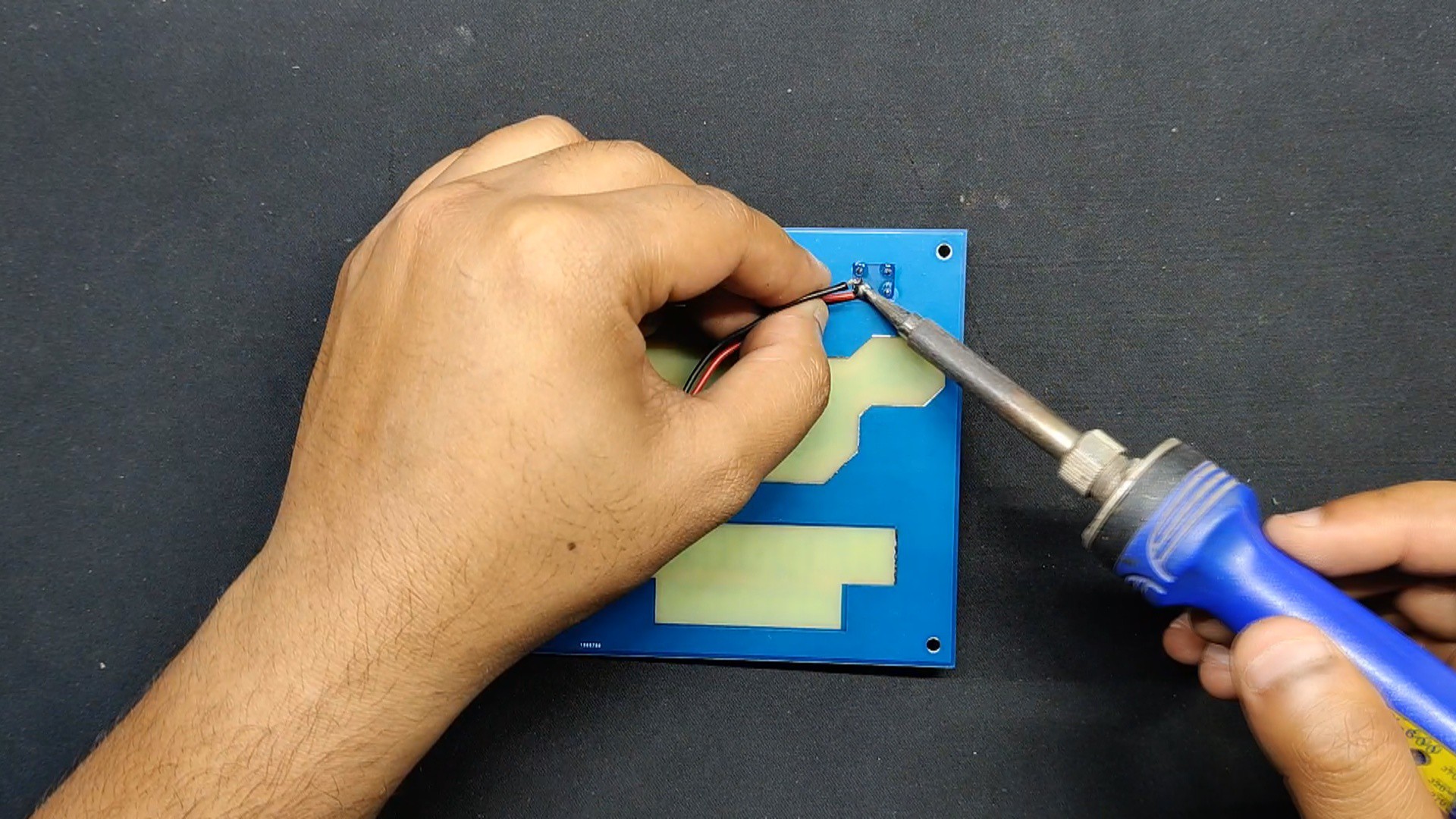
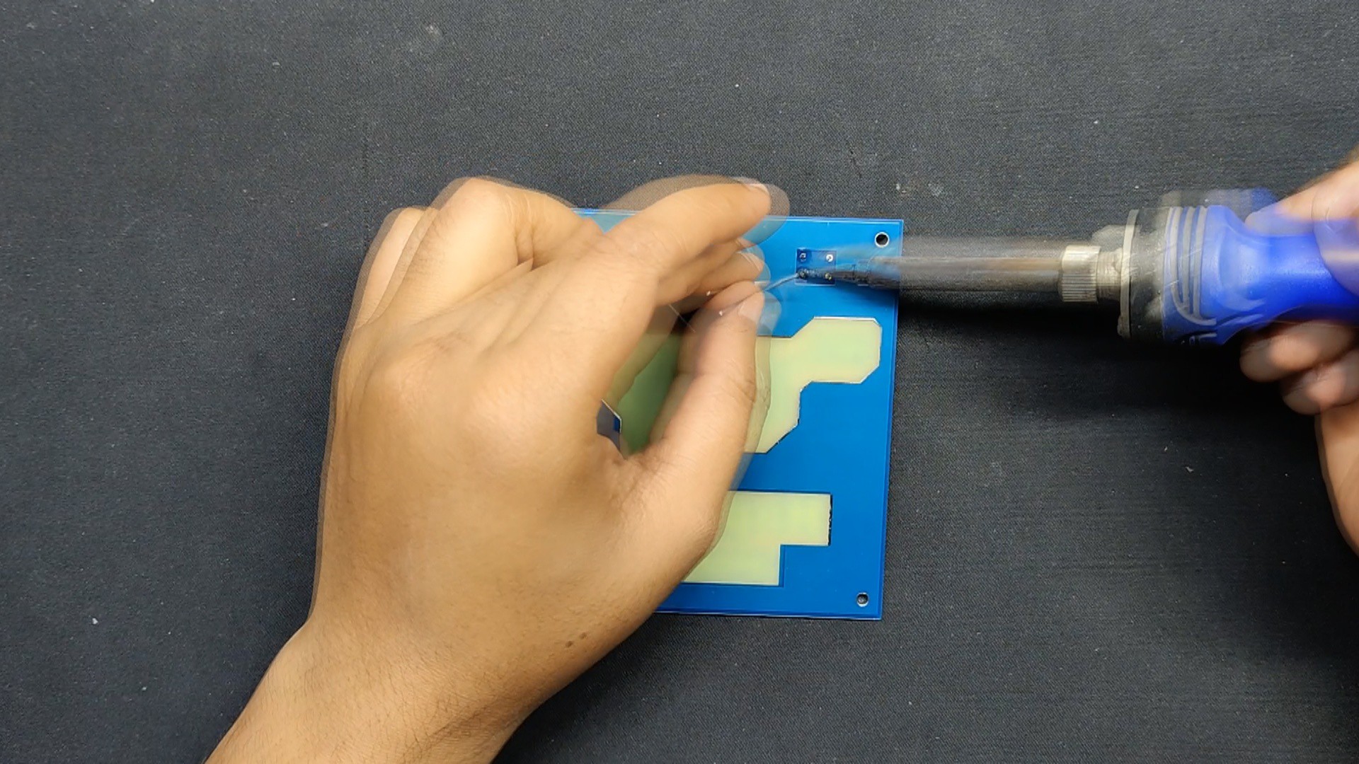
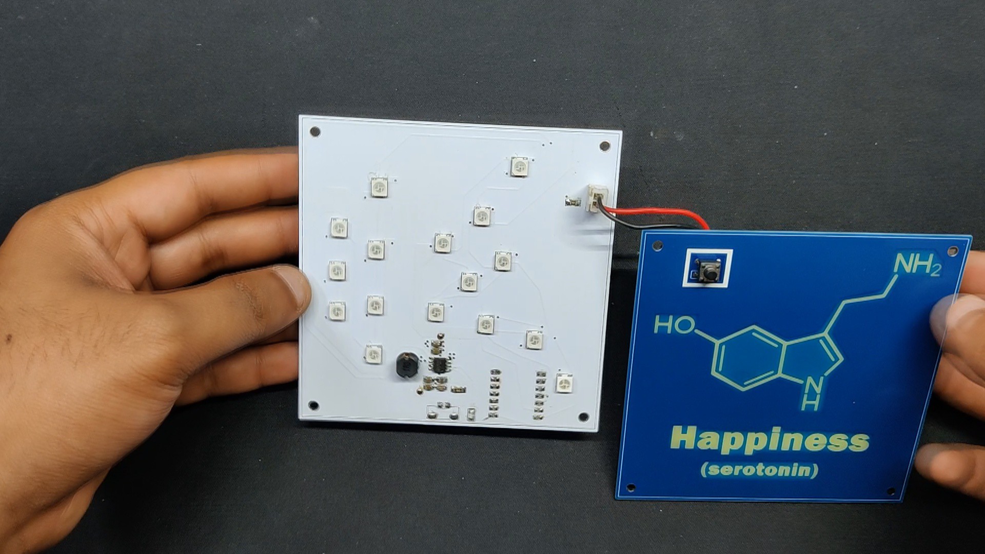
For this project, we build two PCBs: the main circuit board, which houses the power management board, LED array, and microcontroller setup. The front layer board is an additional board that was included only for aesthetic purposes. It has a single switch that will be used to turn the device on and off and ultimately connect to the main circuit.
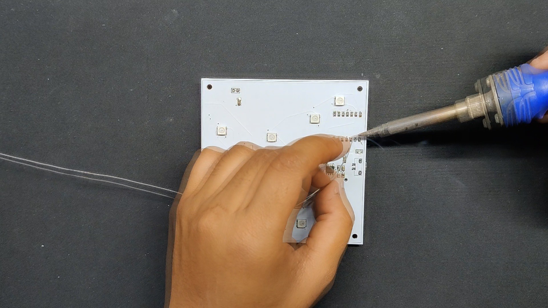
The Seeed XIAO ESP32 C3 Microcontroller, a small and powerful IoT development board developed by Seeed Studio, is the first of three components that make up the Main Circuit board. It has a 32-bit RISC-V processor, Wi-Fi and Bluetooth 5 (LE) connectivity, low power consumption, and multiple interfaces, making it perfect for our project.
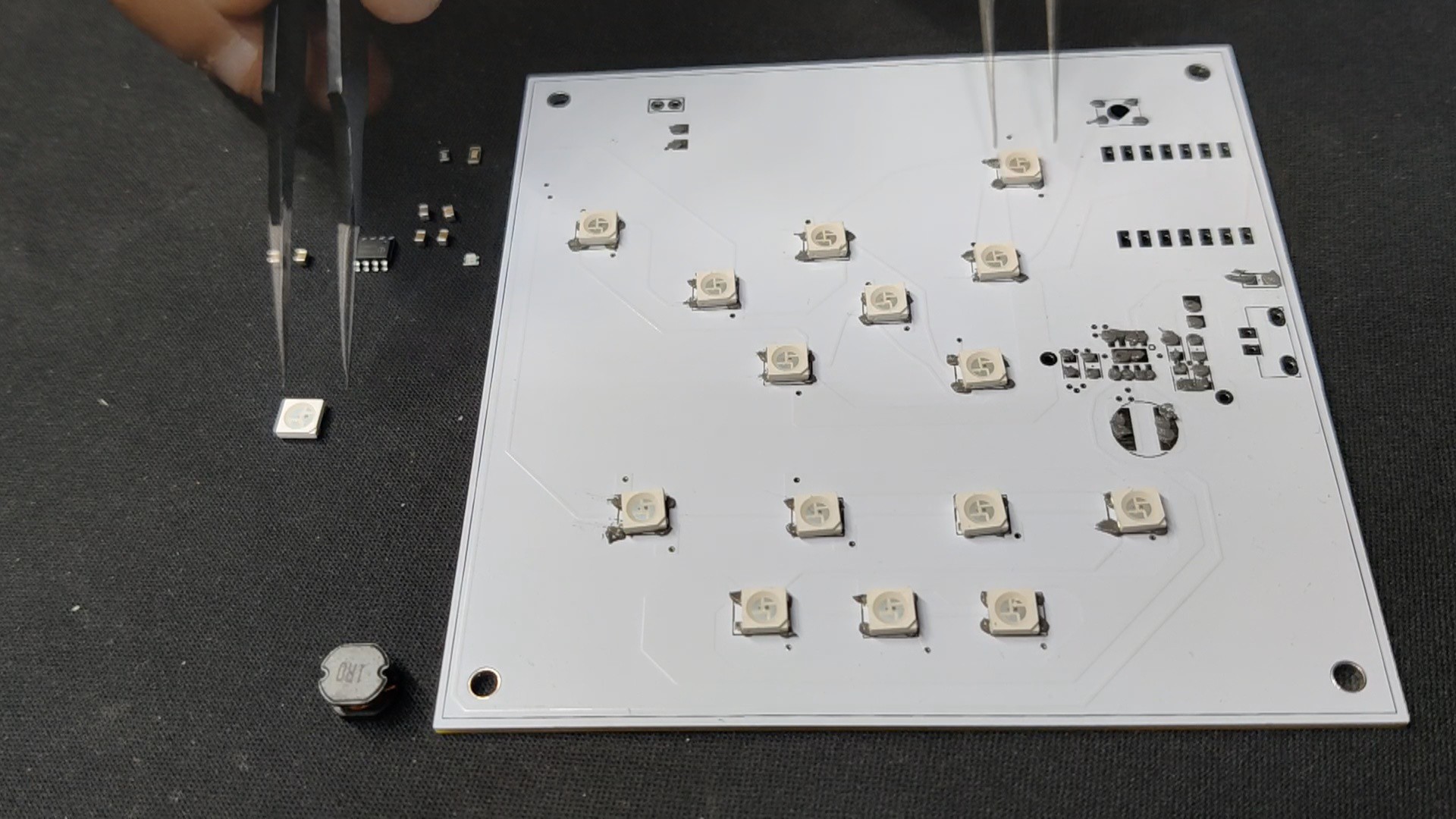
The array of WS2812B LEDs in the second section is all linked in the standard way. The GPIO0 Pin of the XIAO is linked to the Din of the first LED. The Dout of the first LED is connected to the Din of the second, the Dout of the second LED is connected to the Din of the third, and so on, all the way up to the sixteenth LED.
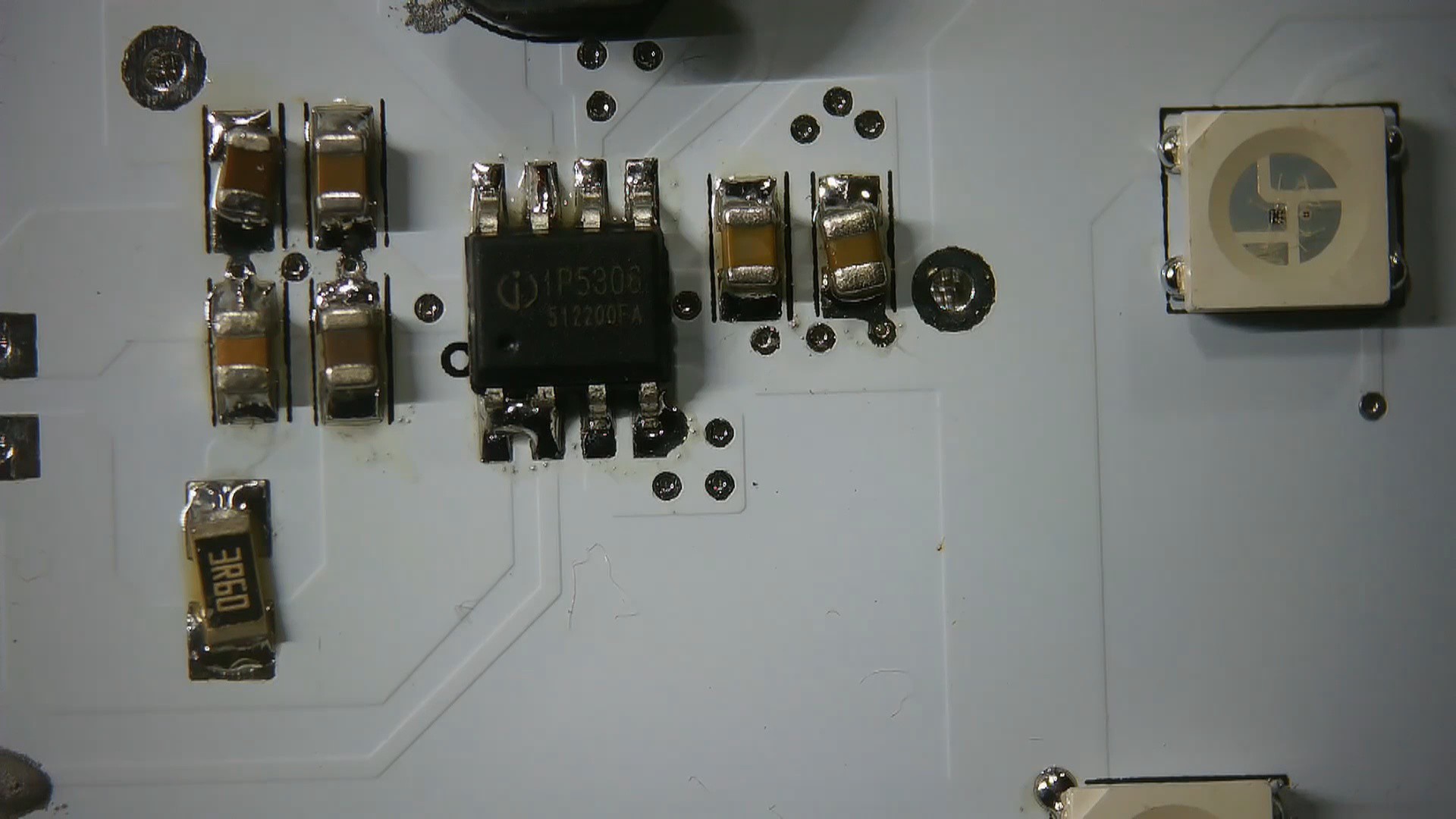
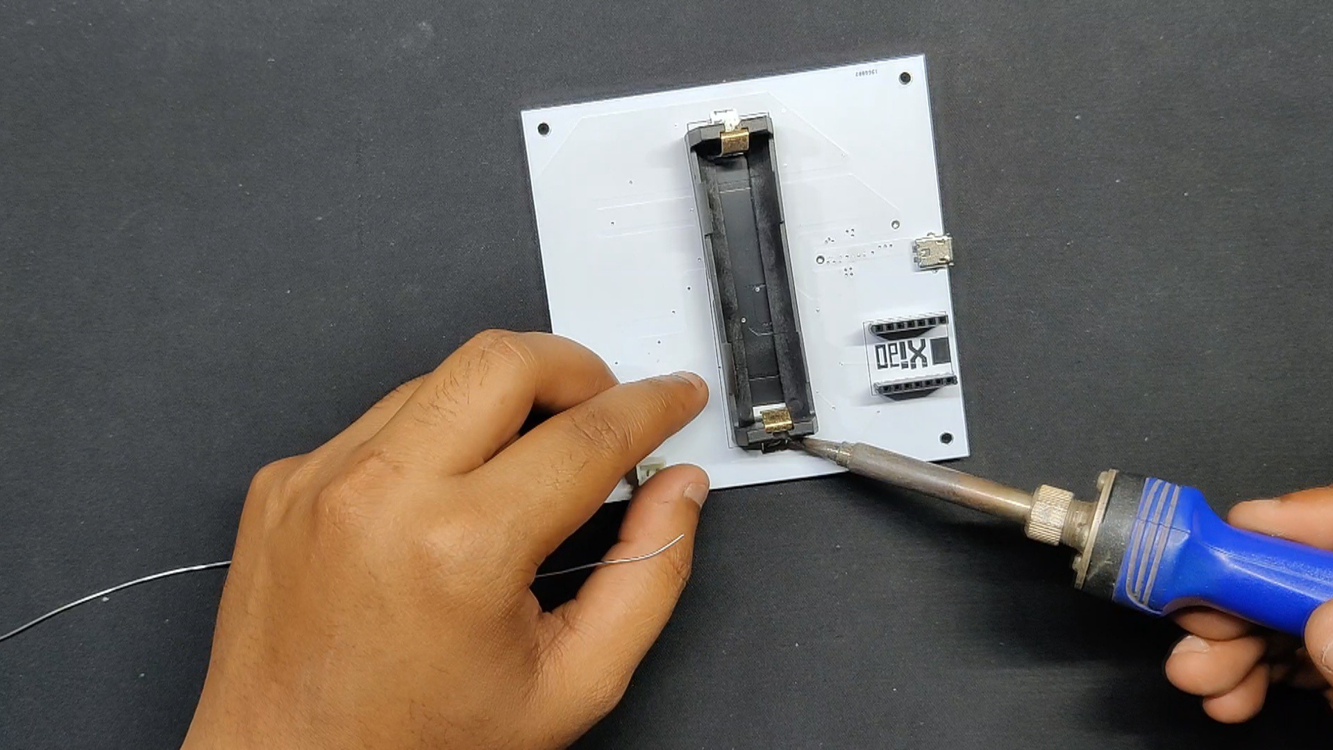
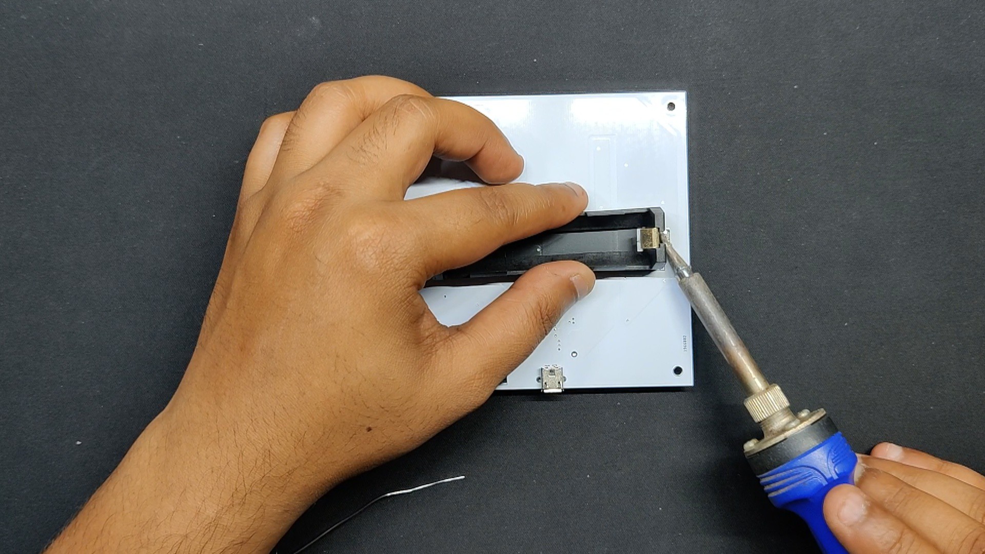
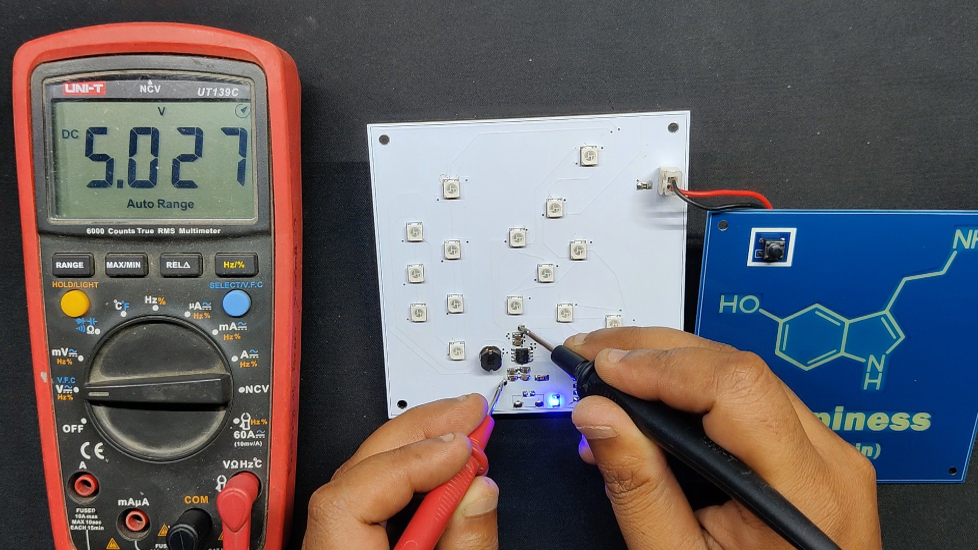
The IP5306 is utilized in the third section of the circuit, which is the power management circuit. It charges and discharges the lithium cell correctly, providing a steady 5V output from a 3.7V lithium cell source.
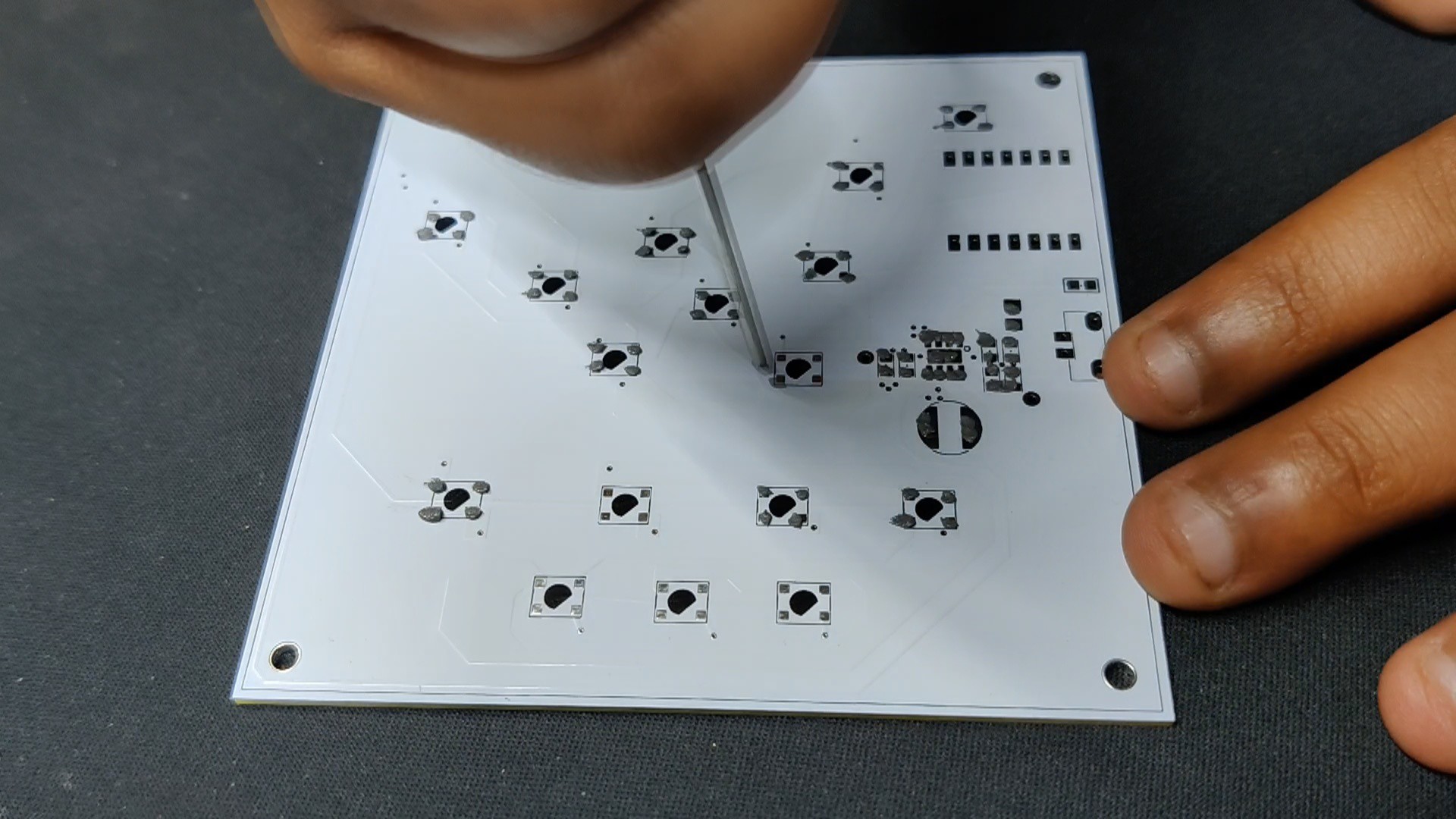
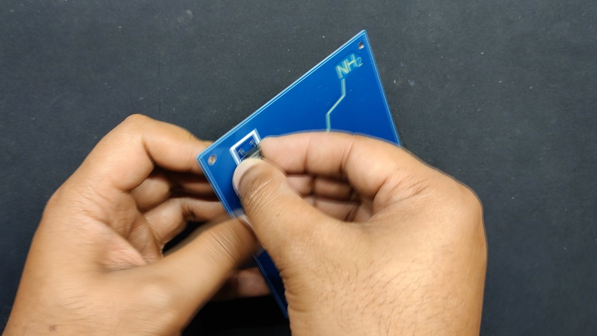
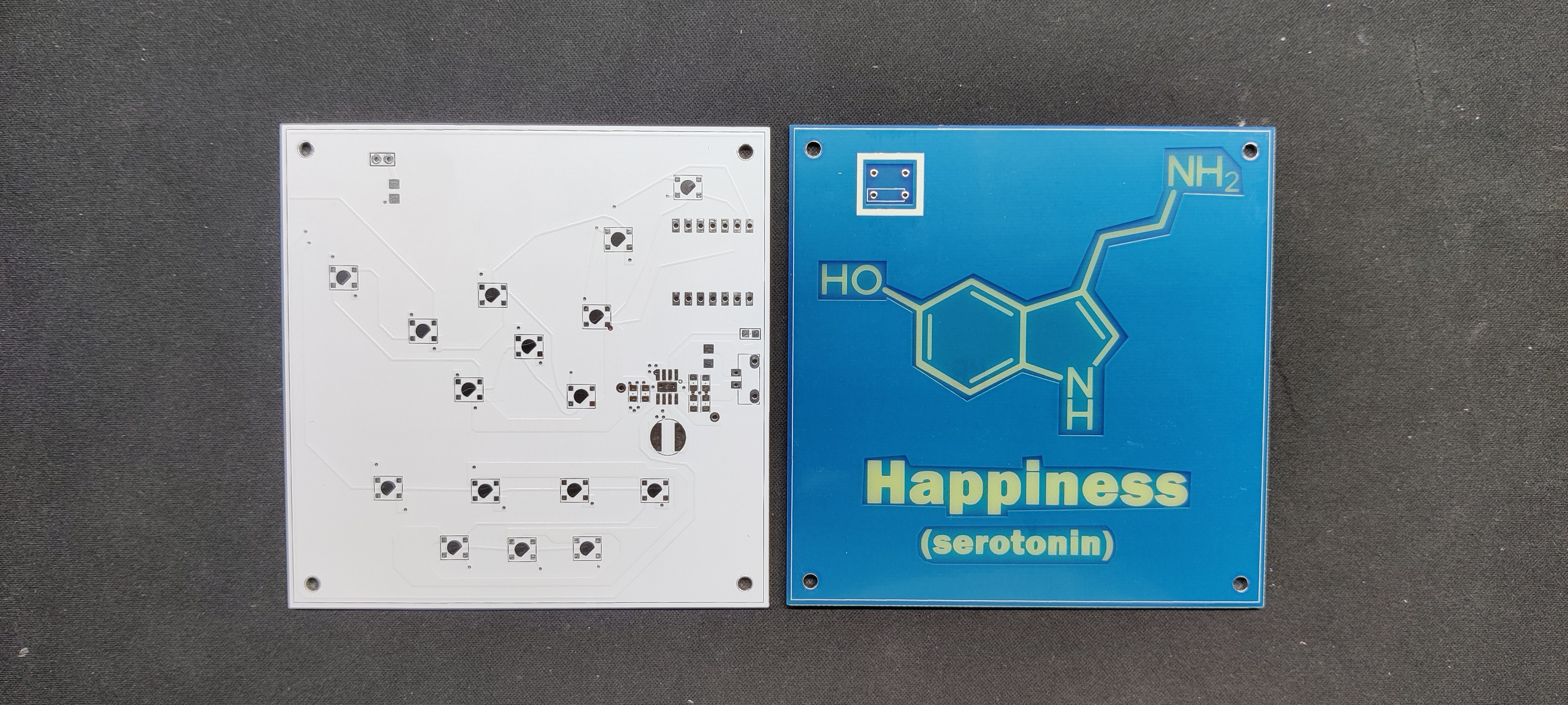
To prepare both boards, we use the same layout of 95x95mm board, which contains mounting holes at each corner of the board. we use the same board outline for making both boards.
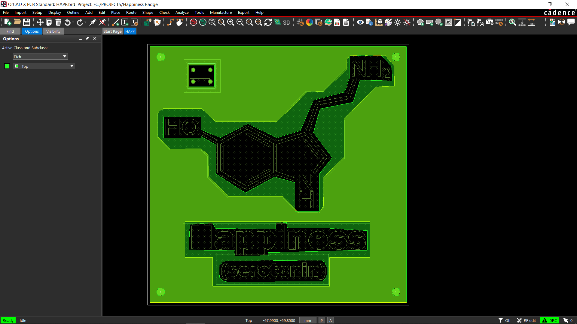
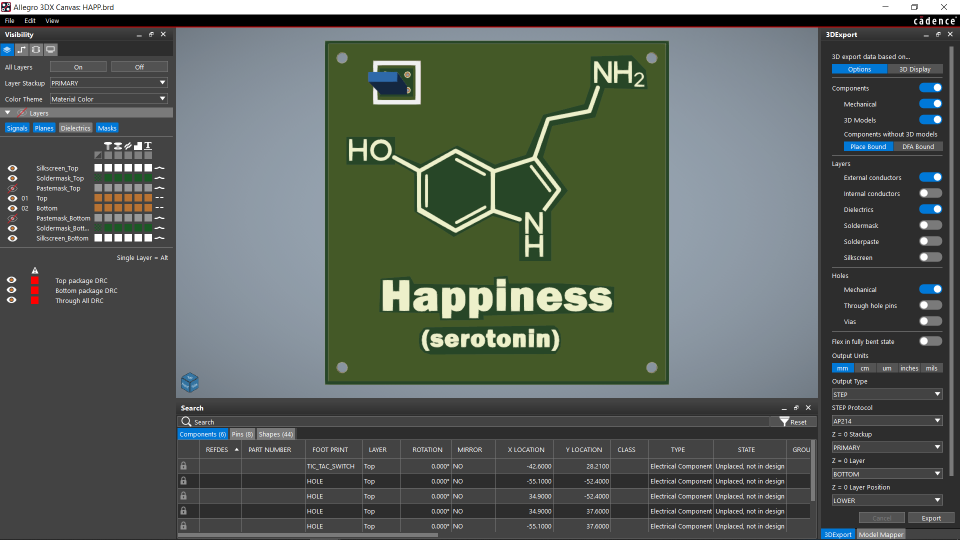
In order to give the front layer a more creative appearance, we also included images of the serotonin chemical structure and letters for happiness. To do this, we looked on Pinterest for an image, converted it to a BMP file, and then imported it as a vector in my PCB Cad software.
I remove all of the letters and lines of the chemical structure from the top and bottom of the solder mask so that light from the main board can pass through.
We exported the gerber data from both files after they were prepared, and we will share it with a PCB manufacturer for samples.
Seeed Studio Fusion
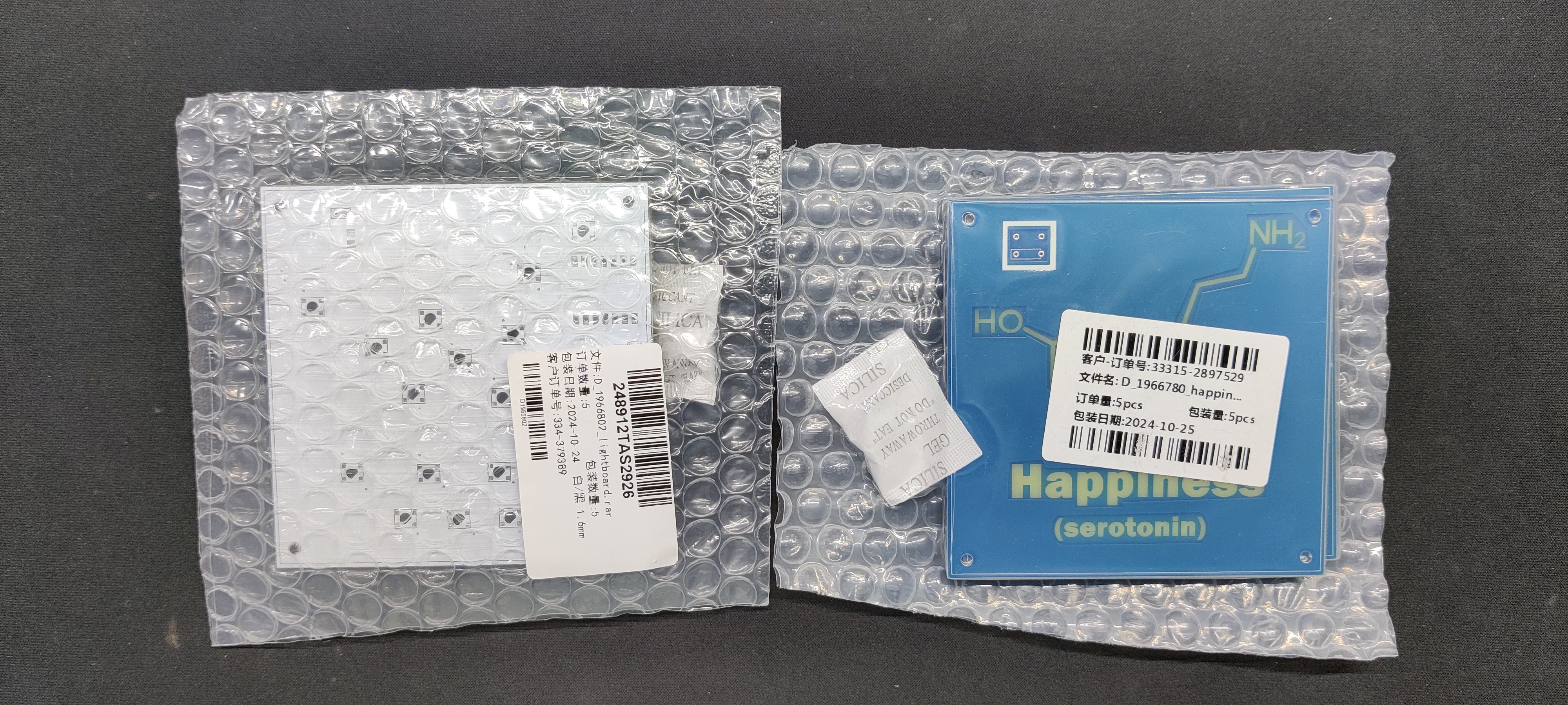
Following the completion of the Gerber data for both PCBs, we uploaded the files to Seeed Fusion's website and ordered two PCBs: one for the blue solder mask and one for the white solder mask.
PCBs were received in a week, and their quality was super good considering the rate, which was also pretty low.
Seeed Fusion PCB Service offers one-stop prototyping for PCB manufacture and PCB assembly, and as a result, they produce superior-quality PCBs and fast turnkey PCBAs within 7 working days.
Seeed Studio Fusion PCB Assembly Service takes care of the entire fabrication process, from Seeed Studio Fusion Agile manufacturing and hardware customization to parts sourcing, assembly, and testing services, so you can be sure that they are getting a quality product.
After gauging market interest and verifying a working prototype, Seeed Propagate Service can help you bring the product to market with professional guidance and a strong network of connections.