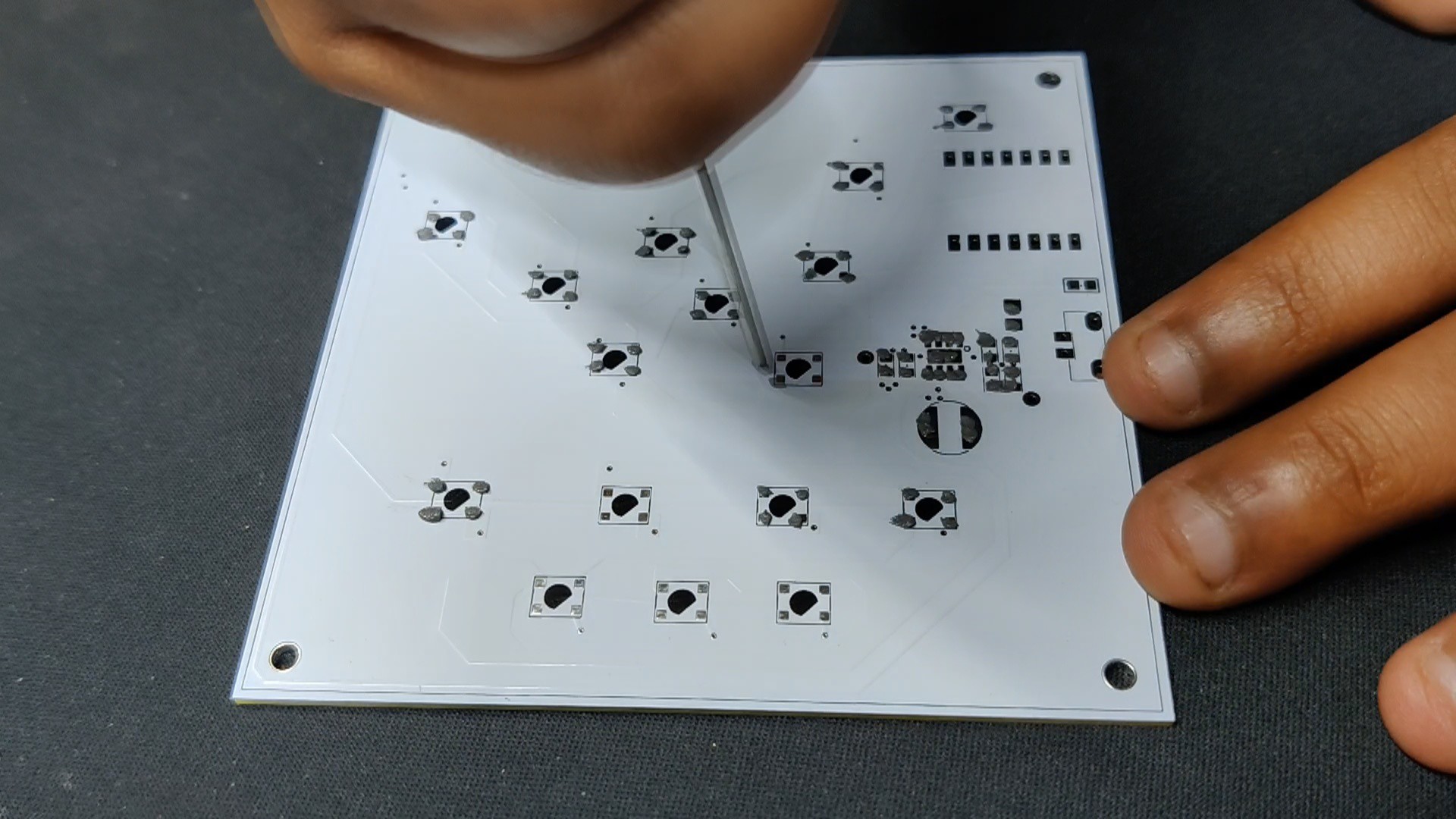
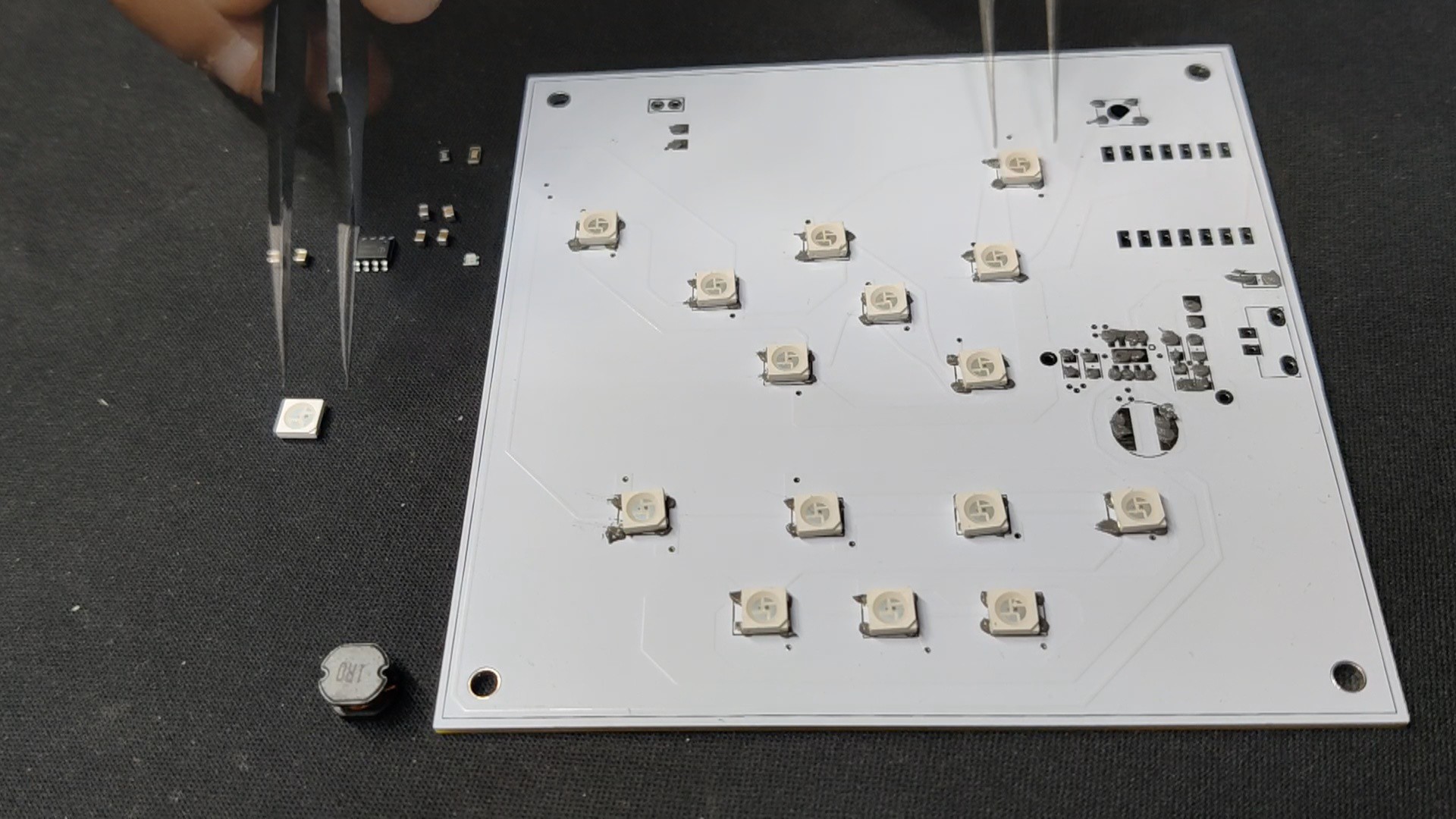
Utilizing a solder paste dispencing syringe, we apply solder paste to each component pad to begin the Main Circuit Assembly process. Here, we are utilizing Sn/Pb 63/37 solder paste, which has a melting temperature of 190°C.
Next, we pick each SMD component and place them in their correct locations.
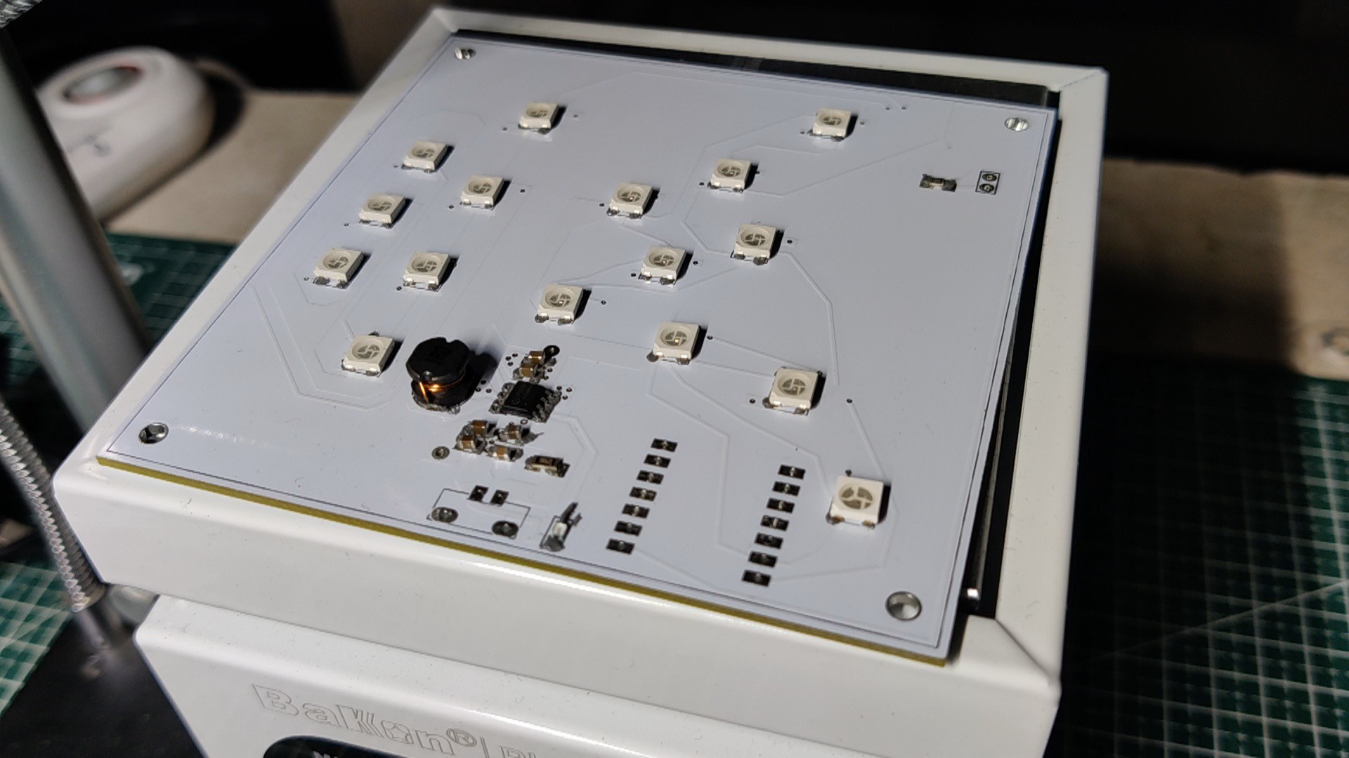
All of the components are then permanently bound to their pads when the entire circuit is set on the reflow hotplate, which heats the PCB to the solder paste melting temperature.
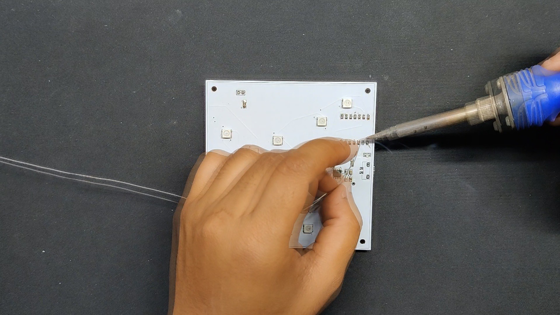
After placing all of the THT components on the bottom side of the board, including the header pins for the XIAO placement, USB Micro port, and CON2 JST connector, we use a soldering iron to attach their pads from the top side.
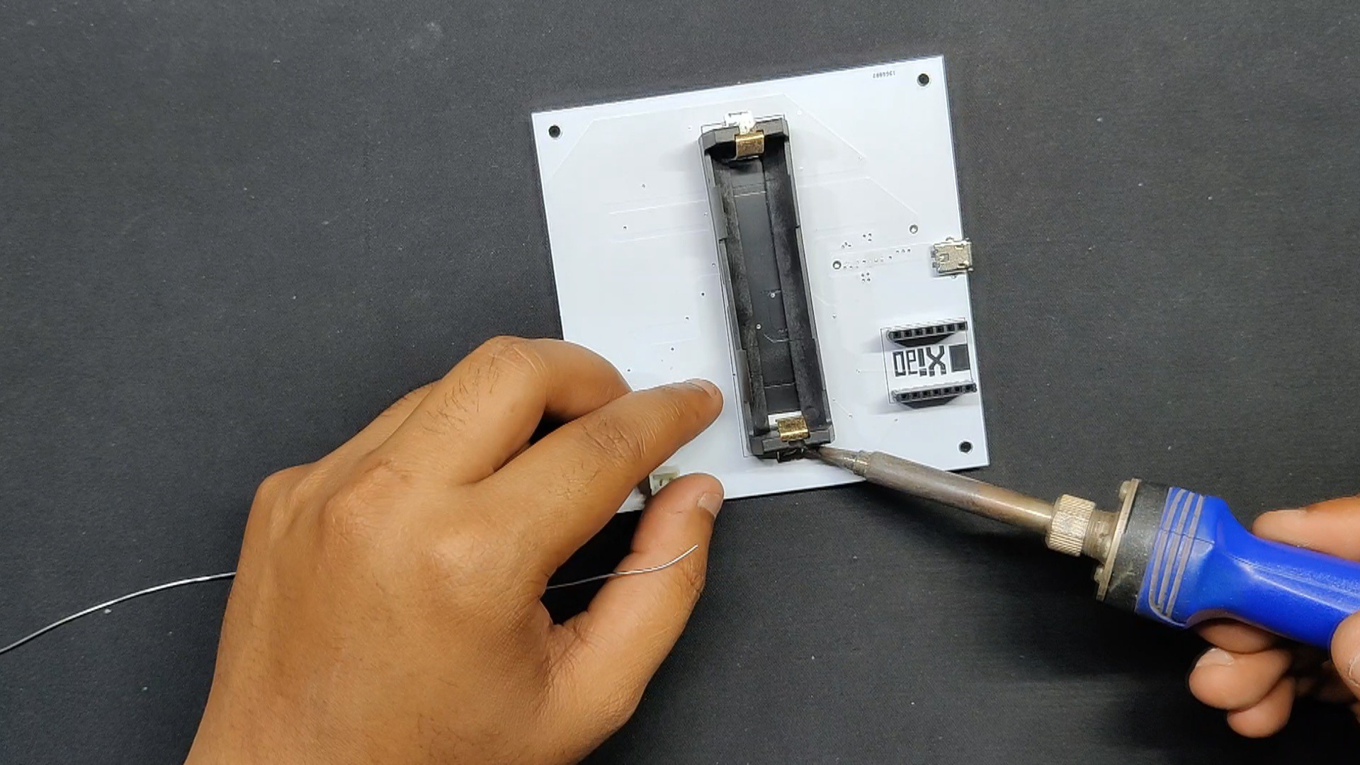
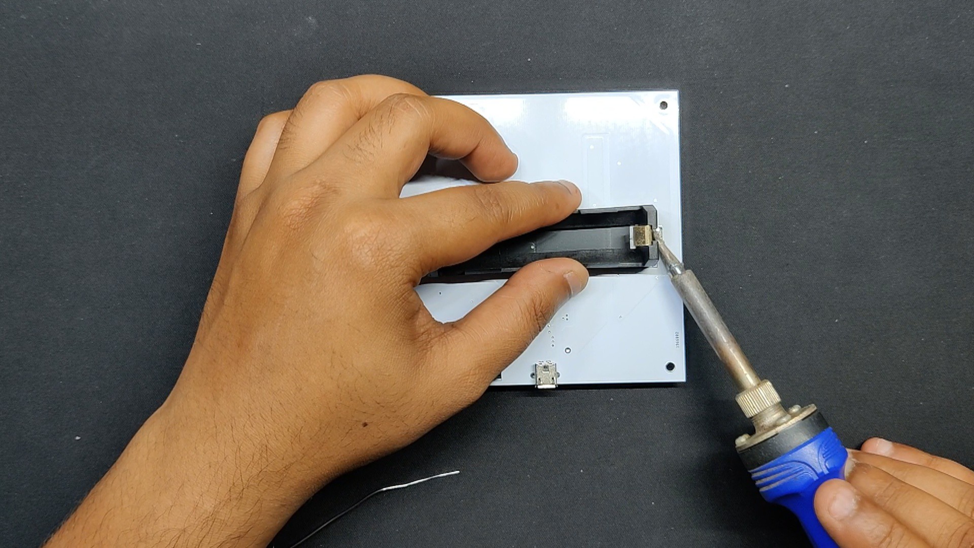
To put a lithium cell holder, we first solder some solder wire on one side of the holder's pad, then link the terminal of the cell holder to the pad to secure it in place. Finally, we solder the other side of the holder to secure it in place.
2
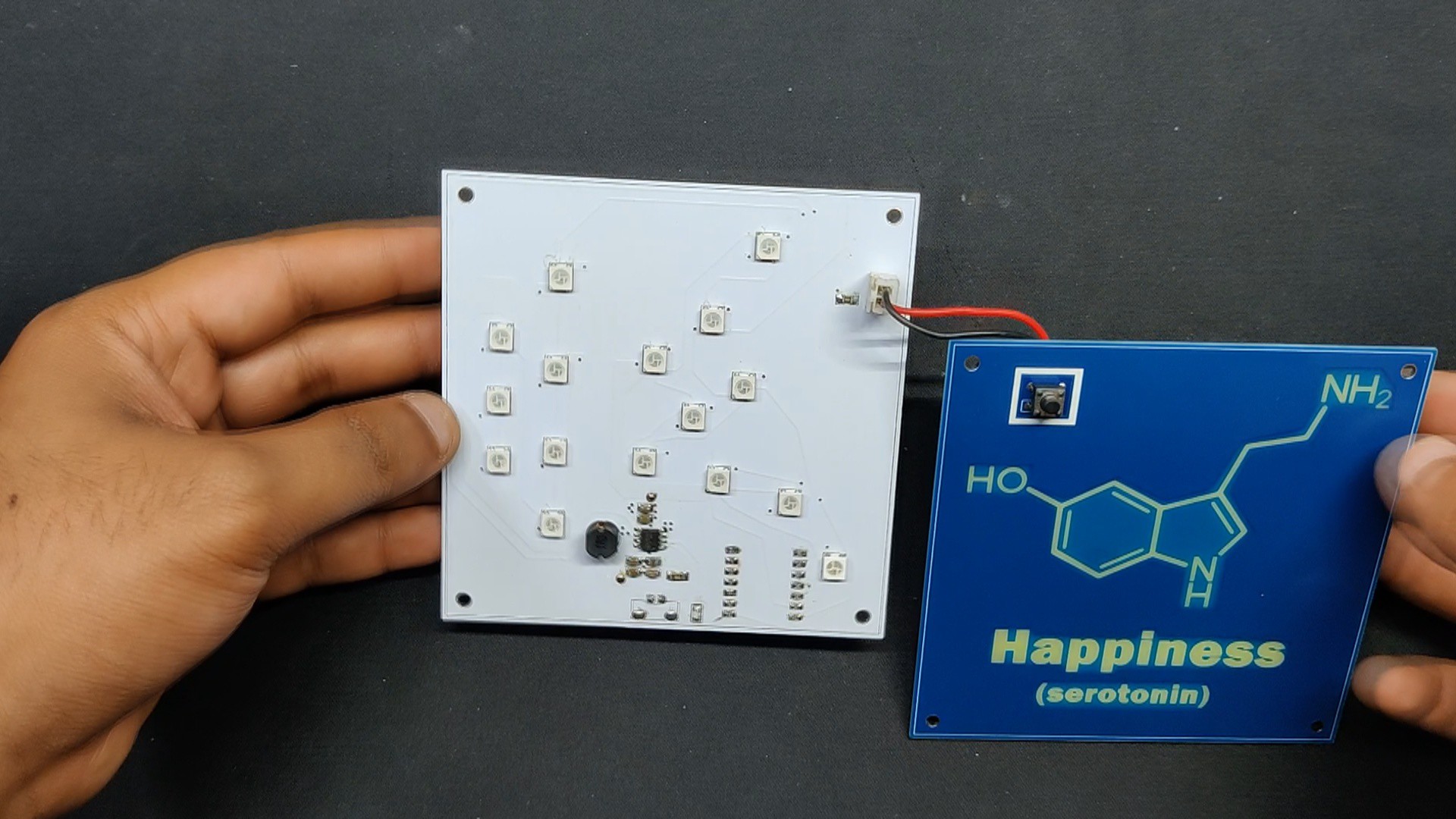
Front Layer Assembly
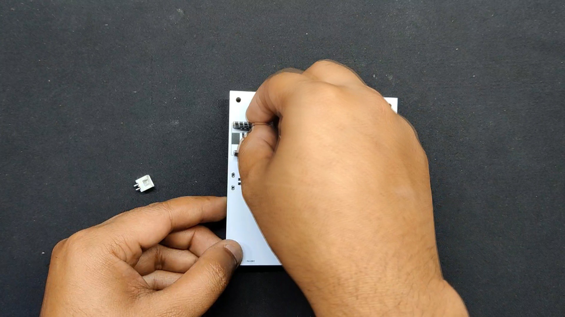
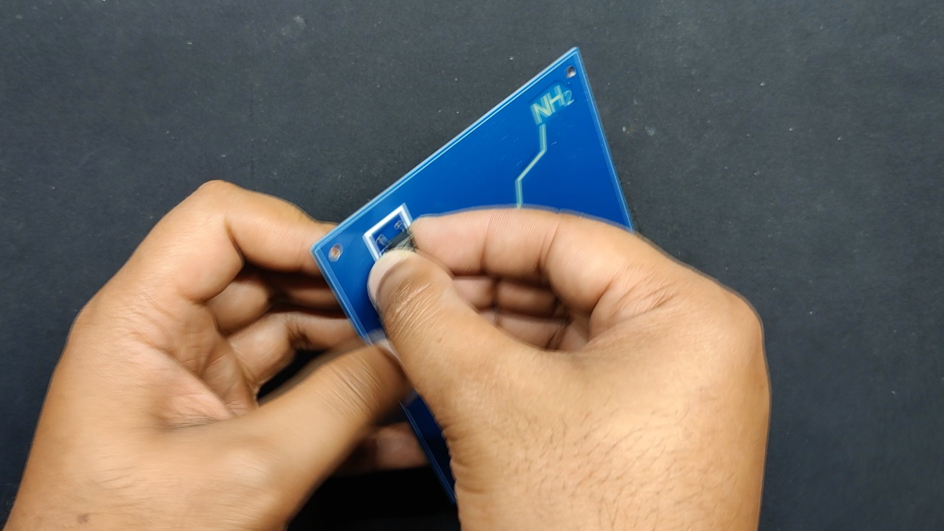
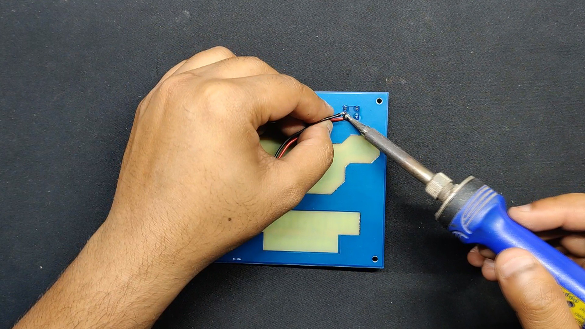
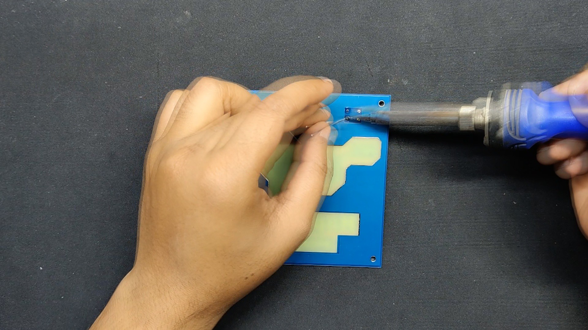
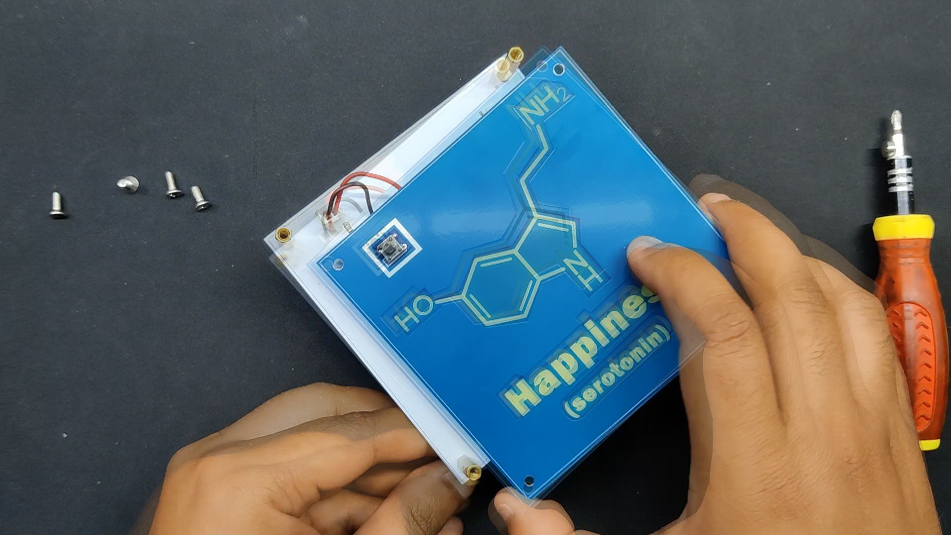
In order to assemble the front PCB, we install a tactile switch and use a soldering iron to connect its pads from the back of the PCB.
For the future coupling of this board with the power board, we then connected a CON2 wire harness to the switch's terminals.
3
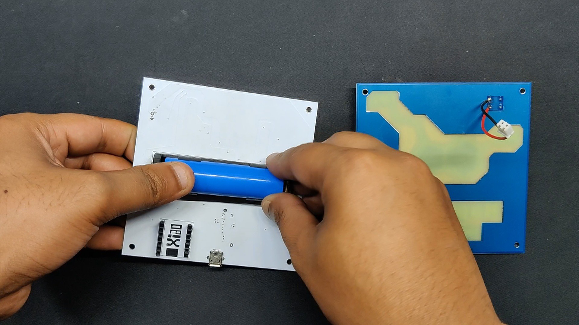
Power Board Testing
A 3.7V 2000mAh Li-ion battery 18650 first goes into the lithium cell holder in the proper orientation to begin the power board testing process.
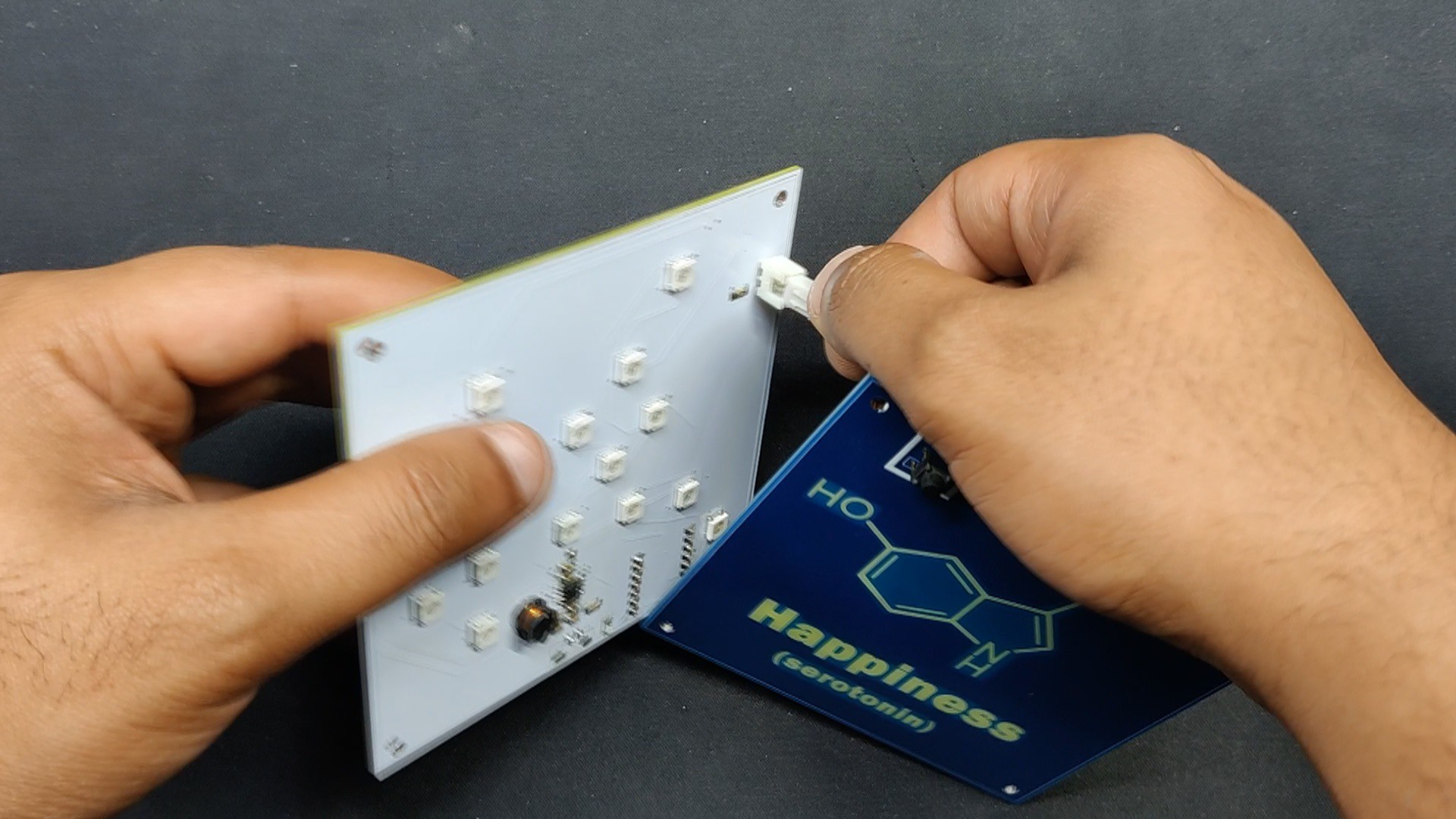
The CON2 wire harness was then connected to the power board's CON2 connector.
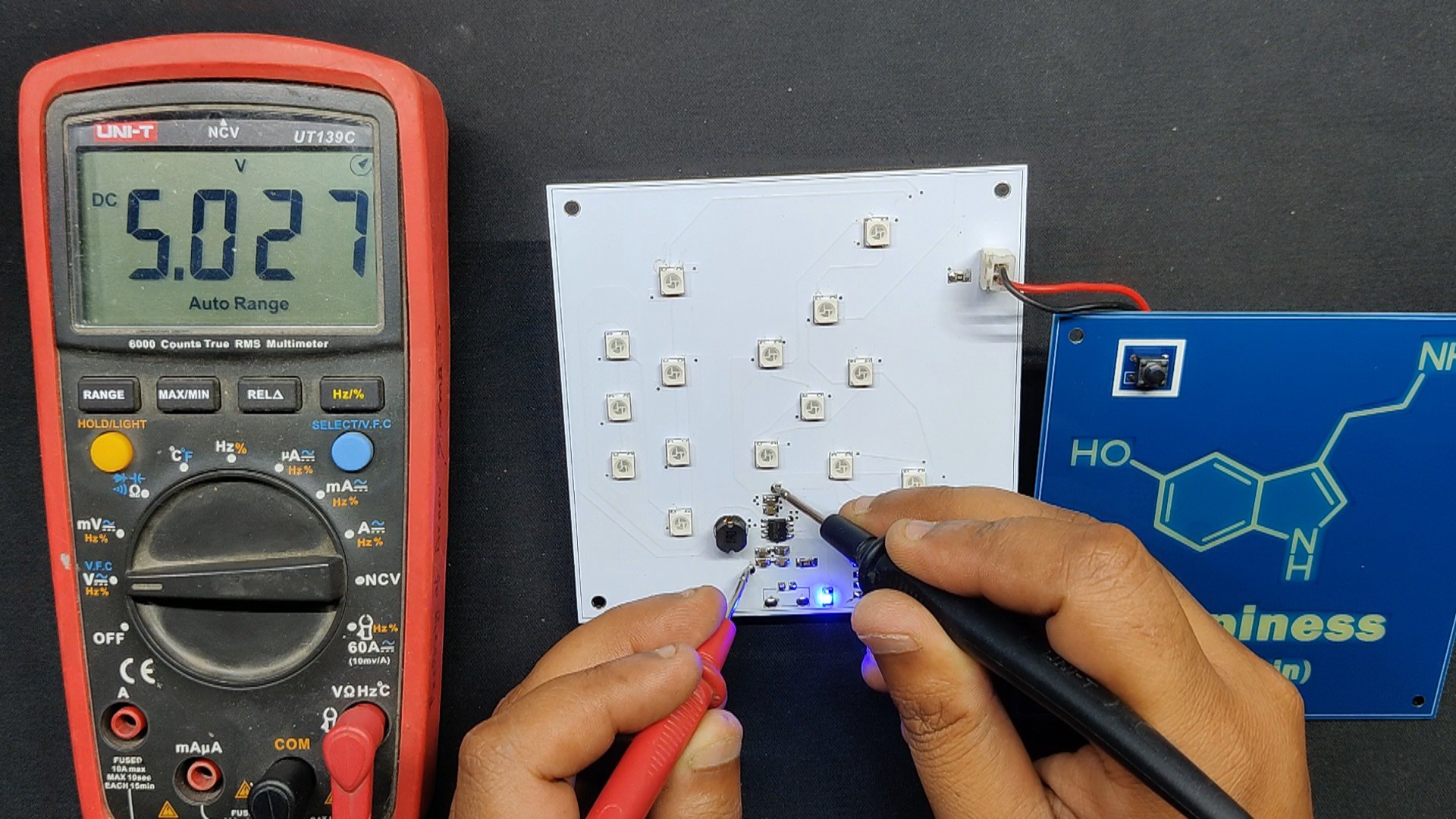
The power board turns on when we press the switch once. Next, we measured the 5V voltage across the IP5306's output terminals.
This indicates that our circuit is operational.
4
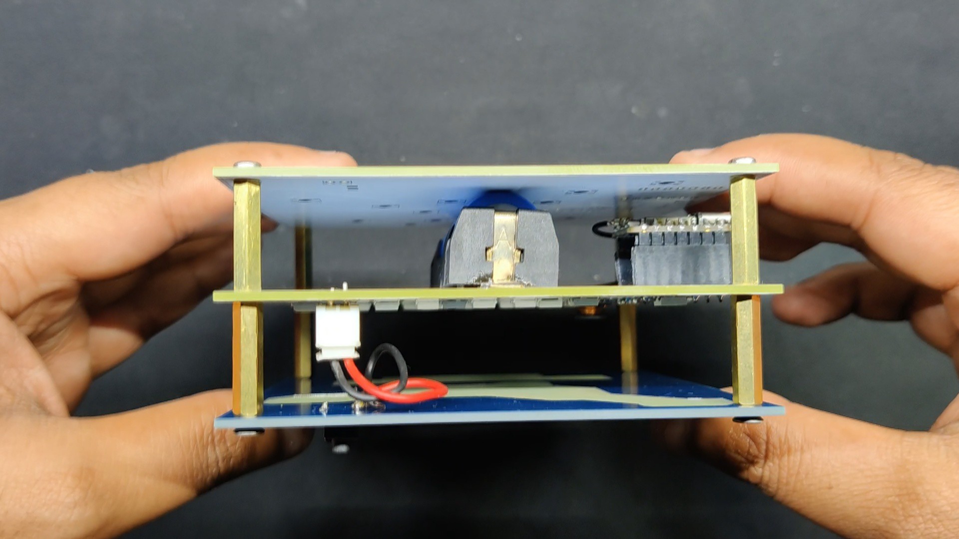
FINAL ASSEMBLY
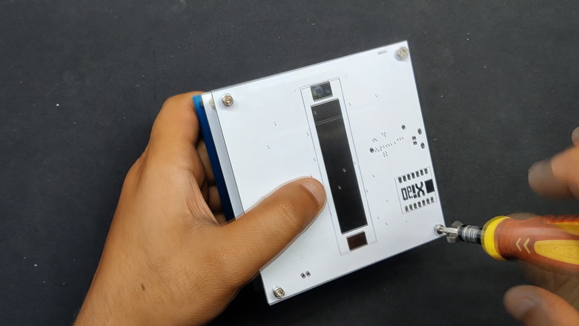
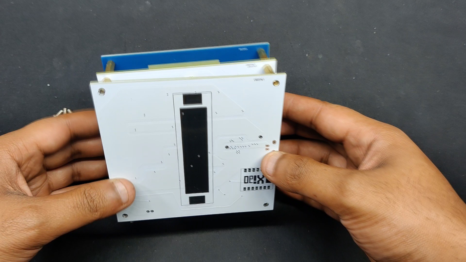
Using PCB standoffs, the Main Circuit Board and the Front Layer Board are connected to start the final assembly. Here, we connect two boards using four M3 22mm Long Standoffs. On the rear side of the main circuit, we also installed four more M3 standoffs, which we want to add a third layer to.
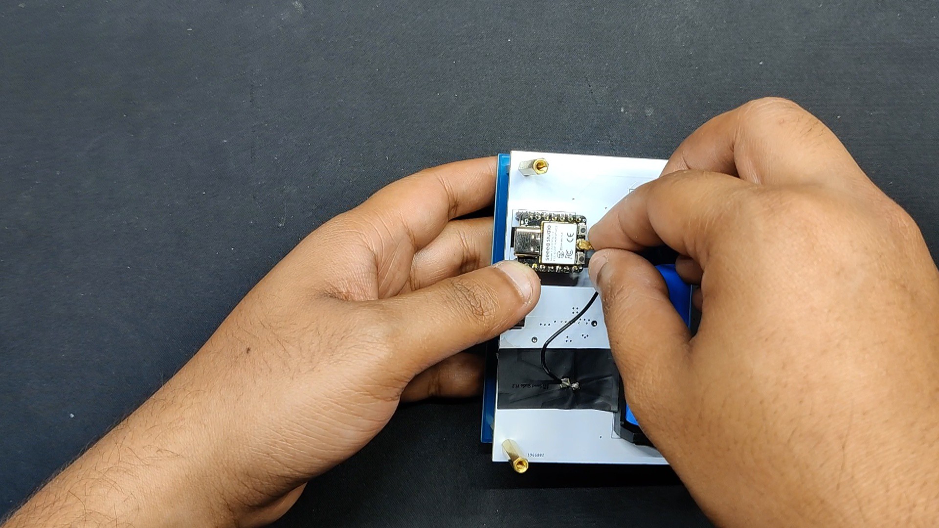
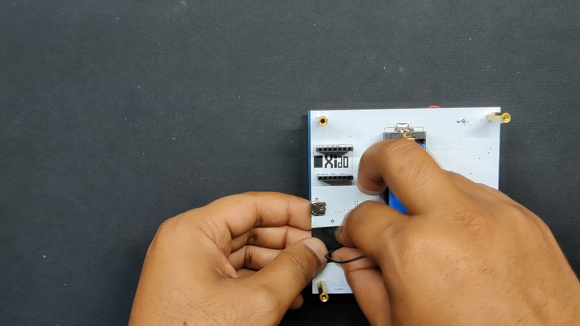
After removing the adhesive patch off the antenna and positioning the antenna on the back of the PCB, we insert the XIAO ESP32 C3 Microcontroller in its place and push it into position on the header pins.
We use a bare main circuit PCB for the third layer, further referred to as the rear layer, and attach it to the device's back side using four M3 bolts.
The third layer is only there to protect the lithium cell and XIAO from the rear.
The PCB has now been assembled.
5
CODE
Here's the code we used in this build, and its a simple one.
#include<WiFi.h>#include<NTPClient.h>#include<WiFiUdp.h>#include<Adafruit_NeoPixel.h>#define LED_PIN D0 // GPIO pin connected to the NeoPixel#define NUM_LEDS 16 // Number of NeoPixels// WiFi credentialsconstchar* ssid = "UR SSID";
constchar* password = "UR PASS";
// Define NeoPixel strip object
Adafruit_NeoPixel strip = Adafruit_NeoPixel(NUM_LEDS, LED_PIN, NEO_GRB + NEO_KHZ800);
// Define NTP Client to get time
WiFiUDP ntpUDP;
NTPClient timeClient(ntpUDP, "pool.ntp.org", 19800, 60000); // IST timezone offset (19800 seconds)unsignedlong lastChange = 0;
bool isWeekend = false;
// Function to connect to Wi-FivoidconnectToWiFi(){
Serial.print("Connecting to WiFi...");
WiFi.begin(ssid, password);
while (WiFi.status() != WL_CONNECTED && millis() < 20000) { // Limit connection attempt to 20 seconds
delay(500);
Serial.print(".");
}
if (WiFi.status() == WL_CONNECTED) {
Serial.println("Connected to WiFi");
} else {
Serial.println("Failed to connect to WiFi");
}
}
voidsetup(){
Serial.begin(115200);
strip.begin();
strip.show(); // Initialize all pixels to 'off'
connectToWiFi();
timeClient.begin();
}
voidloop(){
if (WiFi.status() == WL_CONNECTED) {
timeClient.update();
int dayOfWeek = timeClient.getDay();
isWeekend = (dayOfWeek == 0 || dayOfWeek == 6);
} else {
// Default behavior to alternate colors if not connected to Wi-Fiif (millis() - lastChange > 10000) { // Change color every 10 seconds
isWeekend = !isWeekend;
lastChange = millis();
}
}
if (isWeekend) {
strip.fill(strip.Color(0, 255, 0), 0, NUM_LEDS); // Green for weekends
} else {
strip.fill(strip.Color(255, 0, 0), 0, NUM_LEDS); // Red for weekdays
}
strip.show();
delay(1000); // Update every second
}
This code connects the XIAO ESP32 C3 microcontroller to a Wi-Fi network, retrieves the current day from an NTP (Network Time Protocol) server, and controls a strip of NeoPixel LEDs to display different colors based on whether it's a weekday or weekend even if the device loses its Wi-Fi connection.
6
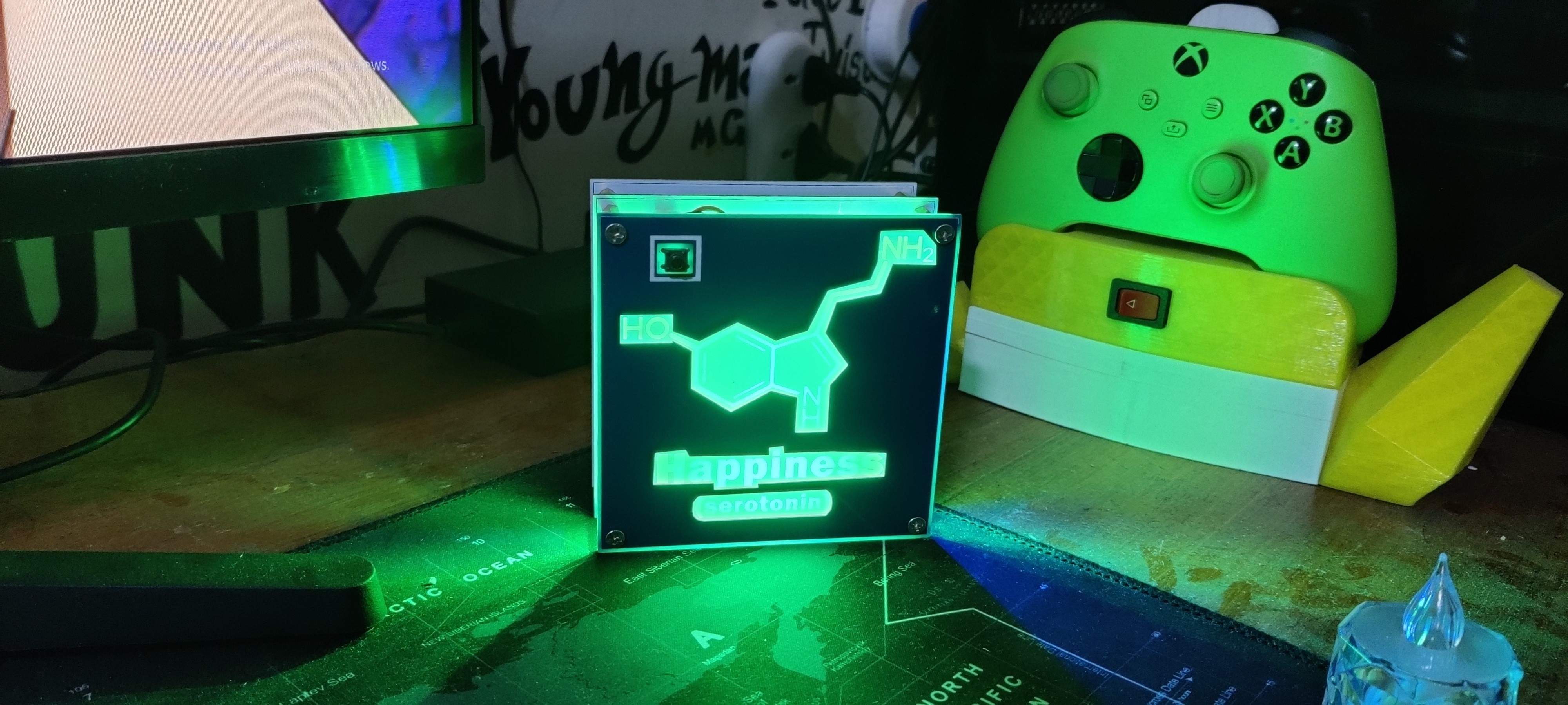
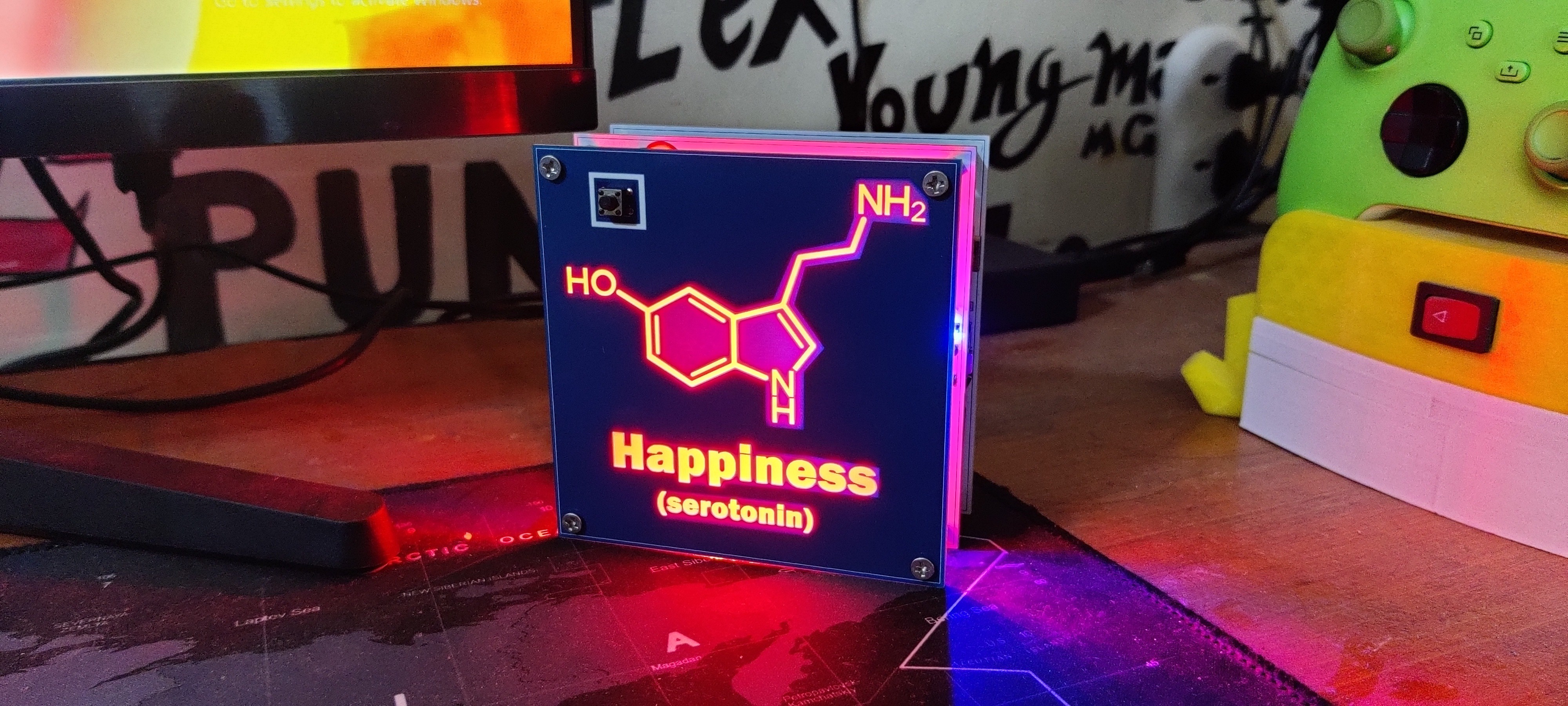
RESULT
Here's the result of this small build, the Happy Week Indicator, a FUN little desk light that glows RED Throughout the weekdays, during weekends it changes color to green, which indicates that its weekends. Green here means happy.
This idea was designed only for amusement; it does have the very little function of showing the days of the week and the weekend, but that can be accomplished with ease by simply checking a calendar or using our phones. That is too boring, which is why we made the device.
For now, this project is finished and needs no further revision.
All the details regarding this project, including files, are attached, which you can download.
Leave a comment if you need any help regarding this project. This is it for today, folks.
 Arnov Sharma
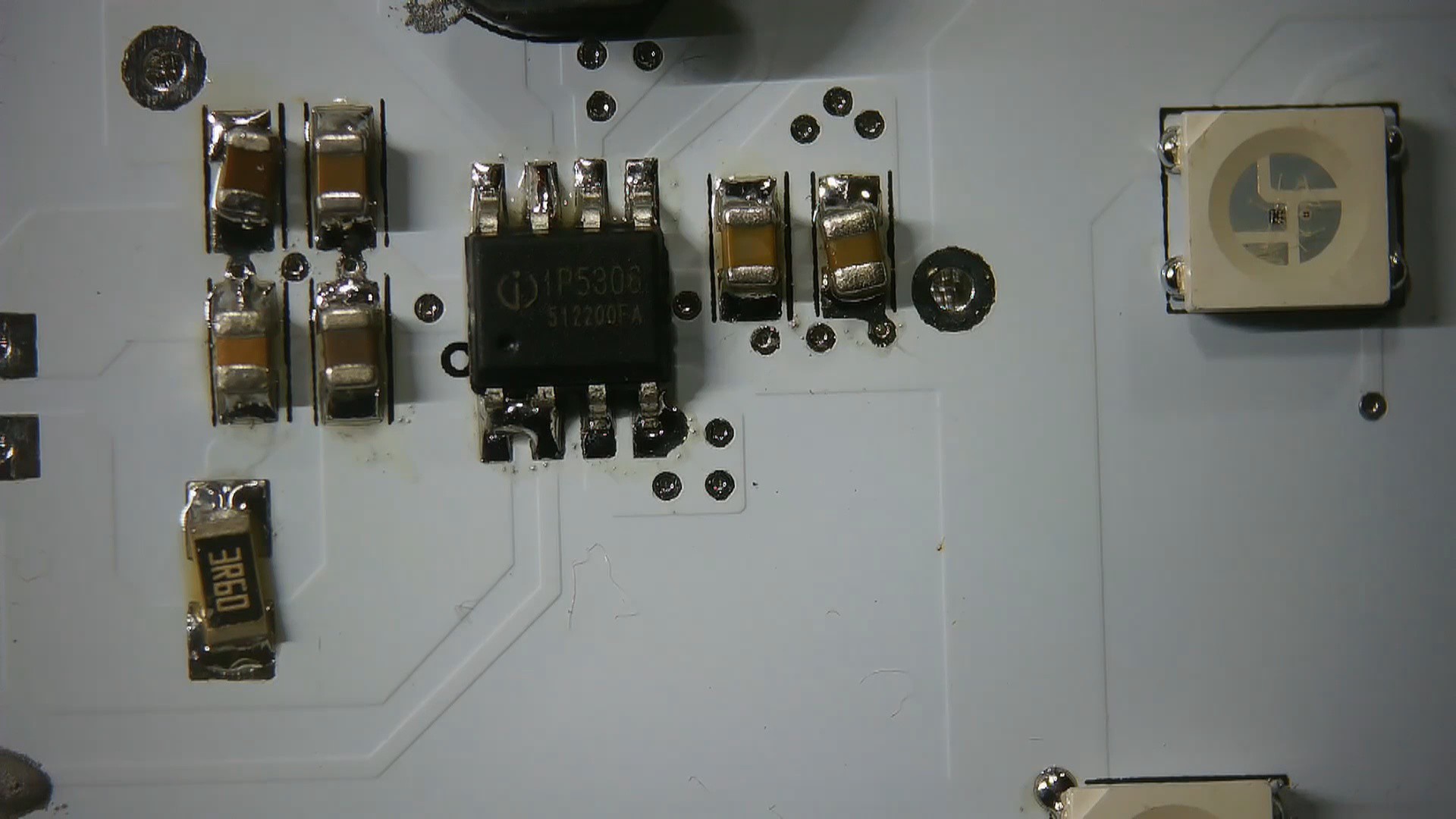

Discussions
Become a Hackaday.io Member
Create an account to leave a comment. Already have an account? Log In.