Close
0%
0%

IoT thermal grayscale printer shield

Arduino shield (will work standalone also) which would print on a thermal paper. Serial, USB and Ethernet communication, open source.

Similar projects worth following
An Internet thermal grayscale printer which could function standalone or in form
of a shield (Arduino compatible). What distinguishes it from other printers is
the unusual technology used, and features that will be available:

* 4 inch wide thermal printer commonly used in financial and medical
equipment.
* Fast Cortex-M4F microcontroller.
* Additional 4 or 8 MB of RAM for image data buffering.
* Ethernet, USB and serial connectivity.
* Prints full scale images in 2 bit “color”. Black, white and 2 shades of gray.
* Can work standalone continuously polling some external, configurable
data stream which could be fed by the users from all over the Web.
* Simple Web interface app to feed the stream and the printer.
* Can work as a printer shield connected to a Arduino (via serial
communication).
* Can work as a regular printer connected to the host computer (I plan to
make it compatible with some Epson flavored printers).

At first I bought broken receipt printer for very little money (like $7). It understood some dialect of ESC/P, but as described on the auction some of it's logic was broken in some way. It would print only one char in a row, and then hang. I described my battle here.

Then I considered whether to abandon the project, or try to use the thermal head itself thus implementing something printer-ish by myself. Without further ado I gained so much information on the topic I could, and after verification that the head is OK i finally got it to print something. This was described in more detail in my other post here :

And after this first success I started to wonder if I could do better, and If gray-scale images are possible. 

What I managed to achieve is depicted somewhere on the left. These images are 4 shades (i.e. black, 2 shades of gray and white), 2 bit deep images. It turns out that thermal printers aren't so good at printing shades of grey though, so the dithering is more apparent than those shades :D Some technical details:

Now it is powered by Texas Instruments TM4C123, but I plan to switch to TM4C129 which has embedded ethernet phy. I plan to attach something like 8MB of RAM, and make it compatible with some popular platform like Arduino. But it could work standalone of course as a USB or network printer (compatible with some simple dot-matrix one). Another feature I was thinking of, was to embed some simple web client which would download and print some data from somewhere (like facebook, twitter or this new data.sparkfun.com maybe?)

The system design document required by 2nd stage can be found here.

The only library (or set of libraries bundled together) used for now is the TivaWare which is available partially in terms of BSD, LGPL, GPL, and TI Commercial licenses. The whole bundle is advertised as "free license, and allows royalty-free use" though. License text can be found in the TivaWare package here

Another library that will be used is the ImageMagick distributed under the Apache 2.0 license

Schematic as well as PCB layout will be designed in Eagle and included in the SVN linked down below (only C source is uploaded for now) under the terms of the GPL license.

  • 1 × EK-TM4C123GXL Tiva™ C Series LaunchPad Evaluation Kit
  • 1 × SII LTP-3445 thermal head 832 pixels wide, 203 dpi
  • 1 × Level shifters
  • 1 × H-bridge

  • 2017 Entry!

    lukasz.iwaszkiewicz03/21/2017 at 21:21 0 comments

    !!!Advertisement warning!!!

    Check out my 2017 entry : https://hackaday.io/project/20463-data-flow-language-and-board-for-iot-automation

    Thanks!

  • Image conversion and algorithm

    lukasz.iwaszkiewicz08/18/2014 at 13:07 0 comments

    To print a row on the head, I have to send a stream of 832 bits via HDAT line. I am considering only a graphic data, i.e. printer won't generate any fonts for itself (at least for now). So for purpose of printing any color image in any format, some preprocessing on the host must be undertaken. Steps to do:

    • 1. Resize the image to 832 pixels wide.
    • 2. Reduce the color palette to grayscale.
    • 3. Reduce image depth further to 4 shades i.e. 2 bits per pixel.
    • 4. Apply dithering.
    • 5. Output the raw byte stream.
    • 6. For debugging purposes convert the resulting byte stream to C header, so the test image could be embedded in the source code and later on the flash memory.

    Surprisingly the task was not as easy as I thought. It turns out, that the topic is quite complicated. For example look at those pages listed below, how many detailed information they contain:

    The last one may give you idea what tool I am using. It is a standard command line Swiss army knife for graphics manipulation available (often by default) on any *nix system. BTW my system is a Ubuntu 14.04, 64bit running on i5 and i7. After lots of tweaking (3 evenings or more) I came up with satisfactory solution:

    1. Generate a "color palette". In my case only 4 shades : black, white and two grays:

    convert -size 1x4 gradient:black ~/gradient_levels.png

    2a. Perform steps 1-5 in one go, and output the result in form of viewable PNG image (for easy inspection):

    convert IMG_7245.JPG -resize 832 -colorspace sRGB -set colorspace RGB -colorspace Gray -dither FloydSteinberg -remap ~/gradient_levels.png -depth 2 ~/franek.png

    2b. Or alternatively output in raw format (notice the output image extension):

    convert IMG_7245.JPG -resize 832 -colorspace sRGB -set colorspace RGB -colorspace Gray -dither FloydSteinberg -remap ~/gradient_levels.png -depth 2 ~/franek.gray

    3. Make a *.h file (huge):

    xxd -i ~/franek.gray > /home/iwasz/workspace/test07/src/franek.h

    Resulting *.h file can be quite huge. Look at this for example. Every byte contains 4 pixels, each 2 bits wide. Black ones has value of 0x0, dark gray is 0x1, light gray is 0x2 and white is 0x3. So draft algorithm may look like that :


    bit monochrome[832];

    for each line

        for k = 0; k < number of colors - 1 (i.e. 3); ++k

            for each 2 bit pixel (color)

                if color <= k

                    set corresponding bit in monochrome array to 1;

            transfer monochrome array;

            issue the DST signal;


    In other words I spit the DST signal duration (let it be D ms) to 3 durations. First I turn on all black pixels, turn on the heat and wait D/3 ms. Then I turn on dark gray ones (black are still on) and after turning on the heat I wait another D/3 ms. Finally I add light gray pixels to the ones already switched on and repeat the heating for D/3 ms. This coarse description is implemented here.

  • The grayscale idea

    lukasz.iwaszkiewicz08/18/2014 at 10:14 0 comments

    As I stated in a comment down below, the most tricky part of the whole gizmo is the thermal element of the head. Depending on the model it has typically from something around 300 to 832 thermal elements which are responsible for printing each dot in a row. So theoretically you can print a black line spanning the whole paper width at once, but this would involve heating up all 832 heat elements at once too (i refer to my original head which is 4 inches wide and has 832 pixels in row). This in turn require lots of current, because each pixel is lit by applying some quantity of heat, and heat requires power. Thus heads are divided into pages which can be turned on and off independently, which gives you an option to divide printing a row into smaller and less power hungry tasks. Every page is activated by its own signal called DST (I'm using SEIKO terminology). Basically driving a DST-n line high applies heat to all heat elements residing in n-th page whose corresponding bits in the latch register were set to 1 (see my comment somewhere below). Manuals of the heads include quite extensive and complex mathematical formulas for calculating the duration of the DST pulse. It depends on many factors including the paper type, number of pixels simultaneously lit, voltage you are using, temperature of the head and more. At the end you always have a duration which would provide you a clean deep black printout. But I thought that between black and white you could try to print shades of gray simply by dividing the DST duration by some factor. After a little bit of experimentation it turned out that 2 intermediate shades are the best that can be done on my head with paper I had. The most limiting factor here, I think, is the paper which is covered with dye chemicals not evenly enough, which gives you visible artifacts and grain on a solid black printout. Those papers I own are simply not designed for such tasks, but I believe there are better options (take the USG printouts on some glossy thick paper for example). So as you can see, there is no point of increasing the number of intermediate shades of gray due to inaccuracy of the result. In the next post I'll try to explain the basics of the printing algorithm.

  • Rough diagram

    lukasz.iwaszkiewicz07/30/2014 at 22:46 0 comments

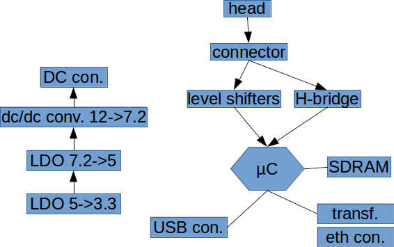
    On the picture below I tried to depict most important or most expensive parts that will comprise my design. On the left side you have power supply part which would provide 3 voltages. 7.2V is for the heaters and the stepper motor (now the lab's power supply is making it). It has to be a switching dc/dc converter because heaters can draw enormous amount of current (). 5V is for the head's logic and in current state 5V is supplied by the USB connected to the TIVA evaluation board which then is passed to the head. 3V3 is for the µC.

    I included the FFC connector on my diagram, because these things tend to be quite expensive when I checked them on farnell and I wanted to include all most expensive parts on the drawing to get a glimpse of what the final cost may be. The plan is to make this device as cheap as possible to be able to eventually make a product out of it.

  • 2 new printer heads

    lukasz.iwaszkiewicz07/22/2014 at 23:00 0 comments

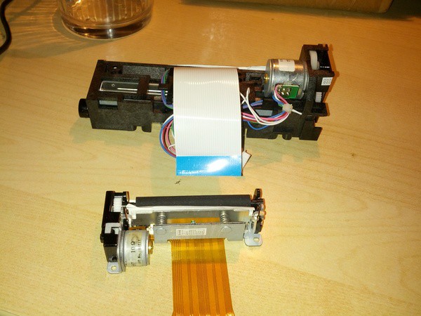
    Brand new heads to experiment with:

    These are newer models of my old head which is now obsolete. Not to mention that these are not original Seiko ones, but cheaper replacements (not so cheap though). The bigger one is compatible with LTPV445 and const me $33 and the smaller one is also compatible with something which Seiko made, but I forgot what. This smaller prints on 2 inch paper and cost $7.50, so it is much more affordable option. But I am still looking for something cheaper, especially regarding this bigger 832 dots wide one.

View all 5 project logs

Enjoy this project?

Share

Discussions

io.kar wrote 08/05/2014 at 12:55 point
I'm really interested in learning more about controlling thermal printer heads. I have a seiko MTP201 B20, and I'd like you to point out any resources that could help me understand how to control it (the manuals were a bit cryptic, and I must confess I'm not much of a low level/hardware guy). At this point any information would be useful!

  Are you sure? yes | no

lukasz.iwaszkiewicz wrote 08/05/2014 at 21:24 point
***Disclaimer : I am an amateur, double check everything I wrote here***

Driving the head is quite easy. I have two types of them. First (SEIKO LTP-3445) is older and has more advanced features (surprisingly), and the second (SEIKO LTPV-445) is newer and is a successor to the first one. In the latter they simplified things a little bit, so driving it is even easier. My heads have a few noticeable parts:

* The stepper motor which feeds the paper (4 wires labeled A, A/, B and B/).
* The heater element. It has multiple leads coming from the device.
* Paper detector (3 wires).
* Lever position detector (also called head-up detector). Two wires.
* Thermistor. It measures temperature of head's heat sink. Temperature range spans from room temperature to something between 80 and 100 C. 100 C is the absolute maximum, and the head should be turned off in this case.

The manuals are written for engineers who develop professional, full blown products, so we, hobbyists don't need to follow them in 100% in my opinion. I think, the most important part is to drive the motor (remember to have paper inside, do not run the motor without it), and then to send the data and issue the heat pulse. All the protection mechanisms can be done later, or even ommited if you are doing proof of concept project.

For driving the motor (which is easier, so I started with it) you need some H-bridge. There are plenty of types of them, so I would pick some (how do they call them? a breakout board?) device from sparkfun or adafruit and try to use it without motor attached (oscilloscope always helps). H-bridge I use is an IC and basically has some input logic pins with high input impedance, so you can drive them with a µC of your choice, and at the other side it has two leads which can supply lots of current (protection diodes are also included in my chip), and, what is most important, polarity of those leads can be swapped. So when single DC motor is attached, it can be driven left, right or stopped. Stepper motors in my heads has two windings, so two H-bridges are used (in single chip). Issuing correct sequence of voltages over its windings turns it one step left or right. If your datasheet does not provide those, look it up over the net, there's tons of info of how to drive a stepper motor.

So now you would transmit a row of data to the head, issue the heat pulse, turn the motor (in my case 2 steps, because of reduction gears) and repeat until there are no rows to transmit.

Communication with the heater element is as follows: First you transmit the data serially using two wires (in my case HDAT and HCLK). Transmission is quite fast, like 4-6 Mbps. Image data should be 1 bit deep, so in my case each row has 832 bits (my head is wide. most heads are shorter). You transmit full row to the head. The heater is split into 13 banks, each having 64 pixels, so next thing you do is to tell the head which banks to activate. The older head (LTP3445) use serial transmission here (BCLK and BDAT) where you transmit 13 bits (sampled on rising edge of BCLK) where each bit corresponds to one bank, and finally you issue the heat pulse (DST wire) which turns on all the necessary pixels in all enabled banks. The newer head I own does not have BCLK and BDAT, but has 13 DST lines. So in this case you issue the heat pulse to those DST lines which has to be turned on.

I am very sorry that I wrote this down quite incoherently, but as you may have noticed English is not the language I speak the best, so be polite. Also, please ask more detailed questions, I'll do my best to answer.

  Are you sure? yes | no

Similar Projects

Does this project spark your interest?

Become a member to follow this project and never miss any updates