 Alastair Young
-
I2C voltage level conundrum
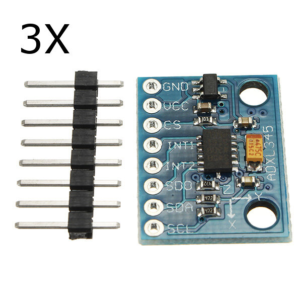
06/30/2019 at 20:29 • 0 commentsThe GY-291 modules arrived today with the ADXL345 accelerometers.
These are a 3v3 chip on a board with a little voltage regulator to drop VCC (i.e. 5V) down to 3v3 and includes I2C pullups to 3V3.
I was thinking that if I am running the I2C at 5V I can insert a voltage level shifter i.e. use the same voltage shifter I use in the MKR I2C shield.
Not so simple. The level shifter needs a reference voltage for both voltages (per the datasheet), I can get the 5V from the I2C line but the 3v3 is not broken out on the GY-291 module.
My first GY-291 modules is DOA. Or maybe I fried it wiring all this up.
The second one works, and does not seem to mind direct connect to the arduino with or without 5V 4.7k pullups. As this would be in parallel with the on-board pullups AND out of spec for the chip, that was just an informational test.
So the carrier board probably wants it's own 3v3 reference..
I verified it all works with the voltage shifter using the circuit on my MKR I2C shield prototype board. Oddly it also work in this mode if I disconnect the 3v3 supply/ reference. This corresponds to Vref_A on the LSF0102.
As it is a pull-down application that kinda makes some sense.
Even more surprising, the LSF0102 still works if Vref_B (5V) is disconnected too. I now have it running with just SCL SDA and GND connected. Again, because it is a pull-down implementation, that makes a tiny amount of sense. So maybe I don't need the 3V3.
However I do want a commonly available locking cable setup, so if I use RJ45/Ethernet, there are 8 wires in there and I can carry 3v3 up from the controller to be sure. If people want to wire it up 4 wire/5V it *might* work anyway.
So the carrier board needs:
- LSF0102 with associated 2 caps and one resistor
- RJ45 header footprint
- 4pin I2C 0.1" footprint + a 3v3 pin on the side.
- grove 90 degree footprint to go the the encoder
- 8pin 0.1" footprint for the GY-291 (female header for easy swap if fried)
- mounting holes
other parts for the kit:
- 8 pin header
- encoder unit
- 2 x 90 degree grove connectors
- grove jumper cable (length?)
- rj-45 connector (use thru-hole)
- rj-45 breakout for the other end? (point to others)
- face mask
- aluminum strip with holes.
- propeller part - 3d print.
- rubber bands
- cuphooks
- 3-d printed housing for electronics - attached to side of facemask.
O
-
Headset Refactor Project
06/26/2019 at 04:29 • 0 commentsLooking to reimagine the headset as the original is very rough and has falling-apart tendencies. Make a batch so other dalek builders can use them.
Thoughts:
- Use my new encoder modules
- Use an off the shelf tilt module for China cheapness. The 2010 option of "buy a used WII nunchuck and cut it in half" is not scalable.
- Skip the microphone. Separate problem.
- Use plugs and proper jumper wires.
- 3-d print bracket so support headside electronics
- put together kits with
- facemask
- swivel arc strip
- spinner
- encoder
- tilt sensor
- tilt sensor adapter board
- bracket
Looking to use the following tilt sensor:
- chip: ADXL345 Initial googling suggest this is well supported for arduino
- module: GY291 is crazy cheap. I can get 4 whole modules from banggood for less than the price of the chip at mouser.
- chip runs at 3.3v, module includes 3.3v regulator and all pullups
- can sit this behind a logic level changer quite happily.
- module pinouts do not match my I2C wiring (wires not adjacent) but I can handle that on the adapter board.
![]()
So job 1 is to pick up a few of these modules and see if they work.
-
Upgrades Complete!
04/21/2017 at 22:07 • 0 commentsFred performed well at the Livermore Innovation Fair, though there is an intermittent short in the head lighting somewhere, resulting in occasional blown fuses. The head lights are off for now until I can track that down.
http://livermoreinnovationfair.org/gallery/
We'll be attending this weekend's March for Science, Livermore local edition. I'm in favour of science, I think it is a huge improvement on just making stuff up randomly and declaring it as fact. Fred may disagree - an Earth with weak science would be easier to exterminate - or may even self-exterminate.
-
PID Tuning The Head
03/25/2017 at 19:43 • 0 comments -
Eye overrun bug fixed
03/13/2017 at 05:39 • 0 comments- Added DALEK REMOTE label to the unused bit of screen
- neodynium magnet mount for remote inside Dalek
- verified code works on actual Dalek
- updated code to use new multiturn mode on eyeACE - eliminates overrun bug.
- https://github.com/arielnh56/freddalek/commit/260ed71b029e91ef493215fea716dee5d9c4652e
-
Remote control enclosure
03/12/2017 at 07:50 • 0 commentsWho needs wireless when you can run I2C over 50 feet?
The way I wired it is
Solid Blue - SCL
Solid Green - SDA
Solid Orange - VCC
Solid Brown - GND
All stripes - GND
My theory is that the twisted pair wiring which prevents cross-talk in Ethernet will do the same for I2C. It works for me.
The objective of this is to move the keypad and new display to a handheld enclosure that can either be hooked inside the Dalek or operated outside. The enclosure has room for more electronics - I already included a rotation sensor - so full external control may be possible in future.
-
Progress Report 3/5/2017
03/06/2017 at 06:29 • 1 commentRambling review of this week's activity in repairing and upgrading Fred the Dalek in time for the Livermore Innovation Faire.
new code branch at
https://github.com/arielnh56/freddalek/tree/add-lcd
Overview of visual menus on lcd
Stuff done this week:
- added lcd support to the menus so I can remember what button does what
- split up the code into multiple files (work in progress)
- bought new batteries - proper deep cycle ones this time
- glued the eye back together. needs filler and paint
- some more glue on the damaged dome
- fixed the dome lock and added a hole so I can lock it from the outside (duh)
- disconnected the shoulder lights. They look crappy anyway and seemed to be the cause of the gun failure (shorting)
- relocated on/off switch so the operator does not nudge by accident.
- new support arm from stainless steel threaded rod. never break again, dammit.
- abandoned brasso in favor of scotch-brite for brasswork
- found all the missing assembly hardware
- glued the tilt sensor onto the headset better
-
transcribing blog entry regarding shield build
02/23/2017 at 06:08 • 0 comments![]()
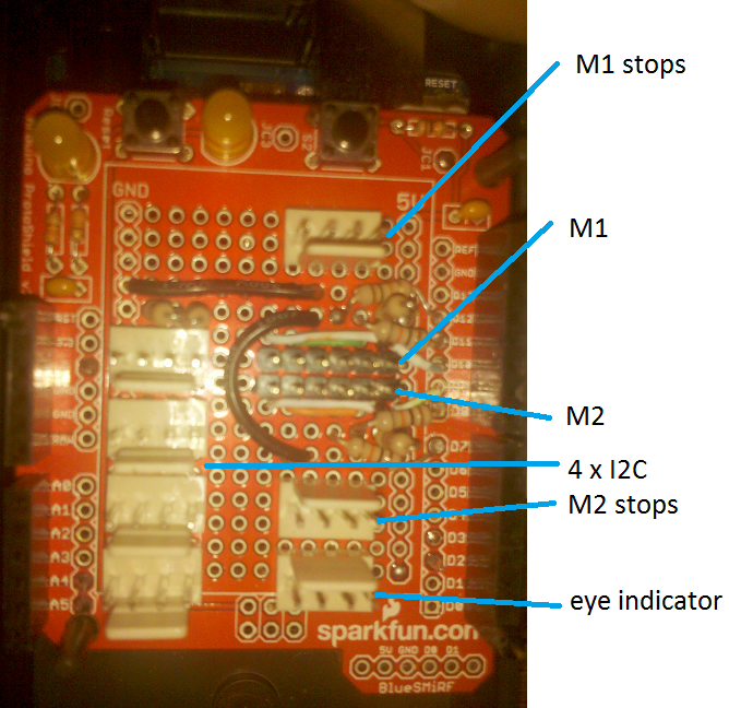
Fred’s new brain is built on the Sparkfun Arduino ProtoShield Kit, though other protoshields would work too. It would make a good basis for other animatronic or robot projects as it is designed to be plug-in.
Wired onto this are
- four I2C connectors, with terminating pullup resistors.
- Two connectors for controlling separate L298N motor controllers
- Connectors for stop switches for the L298N controllers
- Connector for eye position indicator.
I did have a WiiChuck connected into its standard position in A5-A2 via a short extension to a male header so it can mount on the front of the case. However it proved unreliable in the rough environment of real Dalek life, so I chopped it off and used a molex connector instead.
The I2C connector pins are configured -,SDA,+,SCL with the ground pin to the left where the board has a row of ground holes. I chose this pattern as I read that it is good to separate the SDA and SCL lines when using ribbon cables for I2C. As I ended up using Cat5 ethernet cable for my I2C wiring, I could have matched the pinout to one of the other standards. When using Cat5 for I2C, I trim off the brown pair, connect all the stripe wires to ground and allocate the three remaining solid color wires to +, SDA and SCL. This twists each signal and power wire with a ground wire to reduce interference. This works for me.
4.7k pullup resistors tie the SCL and SDA line to +
The I2C connectors are used to plug in the dome and eye position sensors, which are absolute position encoders and a 12 button keypad – all of which use the MCP23008 I/O expander. The final port goes to the headset which has a Wii Nunchuck and another absolute position encoder.
![l298nmodule]()
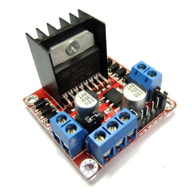
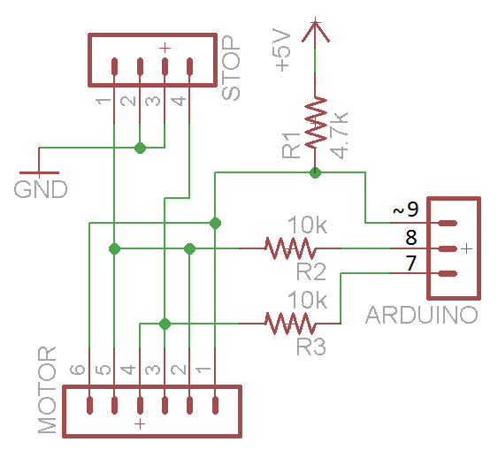
![Motor port and stop switch]() The motor control ports are simple 6-pin male headers designed to connect to these L298N controller modules via a 6-way jumper wire. The L298N is a dual motor controller – actually it is a chip with four half H-bridges. While the normal way to use it is to drive two motors, I am connecting it in its parallel mode for twice the load capacity as the wiper motors are pretty beefy. You could use other controller but these ones are cheap on eBay ($6) and plug in easily, giving access to all 6 control pins. Some modules reduce the pin-count by two by adding an inverter giving you forward and back modes only. This uses less Arduino pins but you lose the braking modes. When configuring the L298N in parallel all the pins need to be paired with their mirror counterpart. On this module this means connecting the middle pins together, the outer pins together and the other pins together, and soldering a pair of wires across the back between the outputs. The motor control ports are adjacent to pins 9 and 10. These pins were chosen as they are controlled by Timer 1 which can be adjusted without impacting other functions in the arduino. The enable pins (outer pins) are connected to the arduino pwm pin and pulled up with a 4.7k resistor to the row of 5V holes. The next two arduino pins on either side are connected to the other motor control pins with 10K resistors. These resistors allow the stop switches to pull down the signal without pulling too much current from the arduino pins. The stop switch connectors have the two middle pins grounded and the two outer pins connected to the motor control inputs. This is easier said with a schematic. Using these cheap external controller is a good alternative to the more expensive integrated shields, particularly if you are operating higher power motors that might fry the controller.
The motor control ports are simple 6-pin male headers designed to connect to these L298N controller modules via a 6-way jumper wire. The L298N is a dual motor controller – actually it is a chip with four half H-bridges. While the normal way to use it is to drive two motors, I am connecting it in its parallel mode for twice the load capacity as the wiper motors are pretty beefy. You could use other controller but these ones are cheap on eBay ($6) and plug in easily, giving access to all 6 control pins. Some modules reduce the pin-count by two by adding an inverter giving you forward and back modes only. This uses less Arduino pins but you lose the braking modes. When configuring the L298N in parallel all the pins need to be paired with their mirror counterpart. On this module this means connecting the middle pins together, the outer pins together and the other pins together, and soldering a pair of wires across the back between the outputs. The motor control ports are adjacent to pins 9 and 10. These pins were chosen as they are controlled by Timer 1 which can be adjusted without impacting other functions in the arduino. The enable pins (outer pins) are connected to the arduino pwm pin and pulled up with a 4.7k resistor to the row of 5V holes. The next two arduino pins on either side are connected to the other motor control pins with 10K resistors. These resistors allow the stop switches to pull down the signal without pulling too much current from the arduino pins. The stop switch connectors have the two middle pins grounded and the two outer pins connected to the motor control inputs. This is easier said with a schematic. Using these cheap external controller is a good alternative to the more expensive integrated shields, particularly if you are operating higher power motors that might fry the controller.
The eye position indicator connector is a straightforward breakout of the +5V and digital pins 3, 4 and 5. This connects to a little board with three LEDs and resistors on it which are programmed to indicate to the operator if the eye is too high, too low or just right, as it is hard to judge from inside.
-
Transcribing old blog entry regarding headset build
02/23/2017 at 06:06 • 0 commentsThis is the motion control headset I put together for controlling my Dalek dome. It tracks the motion of the wearer’s head around 3 axes, though I only use two for the the Dalek.
The basis of the headset is a protective face shield I had lying around, similar to the 3M Professional Faceshield
. An old welding helmet might work too. The shield part is discarded keeping the adjustable part that fits to your head, with the pivot points on either side.
In place of the shield I bent a piece of 1/16″ X 3/4″ aluminum strip with one of my 128 Position Absolute Encoder modules mounted in the middle. This has a flat 16 x 2 lego strip mounted to the shaft, with rubber bands attached to the ends. When in use the rubber bands are attached to cuphooks within the Dalek’s neck, which keep the lego and the shaft of the sensor at a constant angle relative to the Dalek, while still allowing a lot of movement of the operators head.
Mounted to one side of the headset with staples is a piece of plastic liberated from the top a a Tidy Cat container. These are the staple-gun type staples, stapled from the inside and bent over. Onto this plastic is mounted one earpiece and the microphone from a set of gaming headphones. This particular kind came apart in such a way that they could be reassembled through a hole in the plastic, so no glue was needed. The full adjustment of the microphone is retained – the earpiece is disconnected.
On top of the earpiece is mounted the rear half of the internals of a Wii Nunchuck. This half of the board contains the accelerometers. I chopped the joystick part off before I realized there would be space for it, so that could be kept and perhaps used for manual override routines. The half-nunchuck is held on with hot glue. The white block you can see above the board was added for strength.
Connection to the Arduino is via I2C bus, as used by the Nunchuck through its standard cable, though I replaced the connector with a 4 pin molex as the wii standard and wiichuck combination was unreliable in the wild. The encoder is connected to the nunchuck by a ribbon cable, soldered to the pins where the nunchuck wires attach.
The encoder tracks left-right rotation and is mapped directly to the position of the dome which uses an identical encoder on a direct drive. The nunchuck reports angular position for “tilt” (nod) and “roll” (sideways nod). I use the tilt for the eye position with some math to map the nunchuck angle to the eye encoder value. I’m not using the “roll” value at the moment.
If you have a herd of video-gaming kids in your house, cats who chew cables and you never throw anything out, you probably have most of the donor parts to make one of these lying around.
Parts list:
- 128 Position Absolute Encoder module
- full face shield or welding helmet such as 3M Professional Faceshield or SAS Safety 5140
- a Wii Nunchuck (chewed will probably work)
- Aluminum strip 1/16″ X 3/4″ from the metal stock rack at your hardware store
- some ribbon cable from an old computer
- optional for sound: microphone on a bendy headset mount
- lid from a Tidy Cat bucket
- 16 x 2 bump Lego strip
- two rubber bands
- two cuphooks
-
Mandatory credit thing
02/22/2017 at 09:25 • 0 commentsThe quality picture was taken at Maker Faire by the tested.com people as we wandered about. I shamelessly scraped it off their website.
![]()
Dalek head control
System to have the Dalek head follow the operators head leaving hands free for plunger wiggling
 . An old welding helmet might work too. The shield part is discarded keeping the adjustable part that fits to your head, with the pivot points on either side.
