 Peter Walsh
-
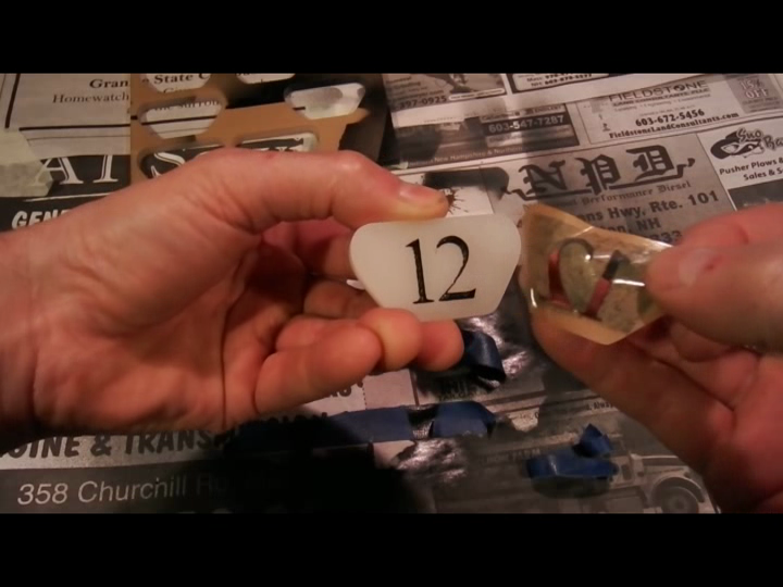
1Step 1
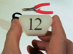
Prep and cut the amulet
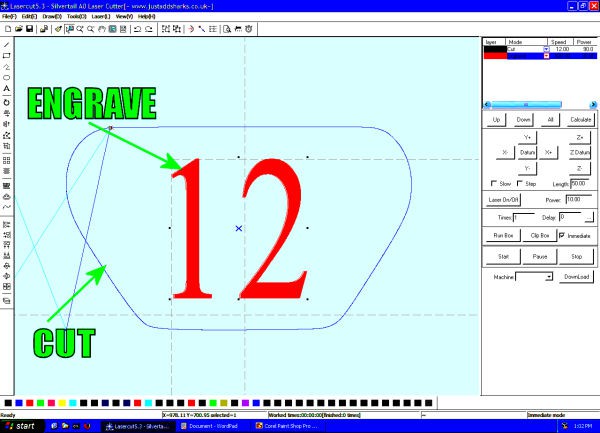
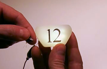
Step 1: Using your laser cutter software, set the outline to "cut" and the digits to "engrave".
The engrave should be low power - only enough to go through the paper backing
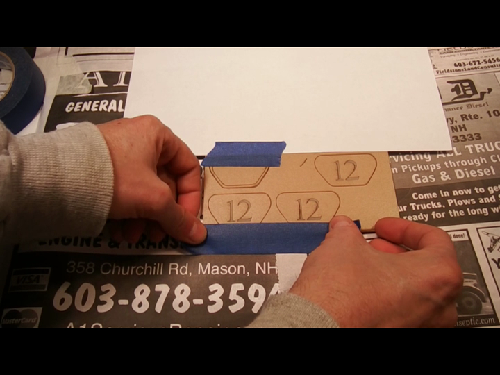
Step 2: Cut the amulet blanks, then mask off everything except the digits.
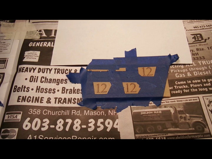
Step 3: Go over the masked digits with black spray paint, and let dry.
Use 3 coats!
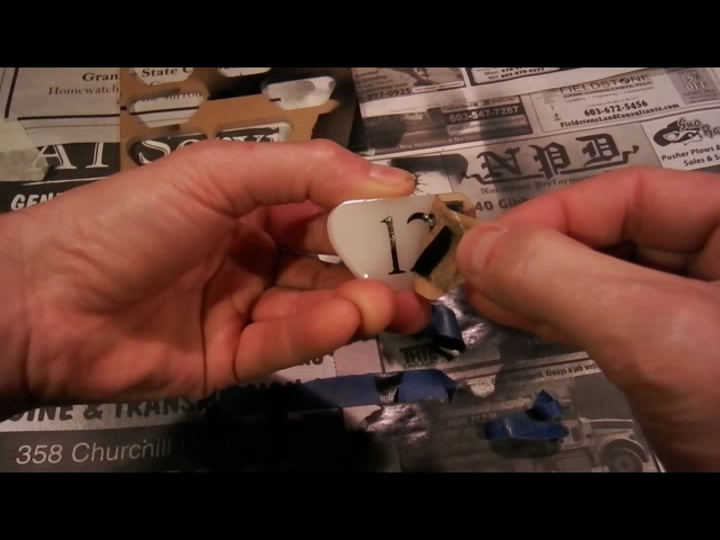
Step 4: Peel off the paper backing to reveal a perfect amulet front.
-
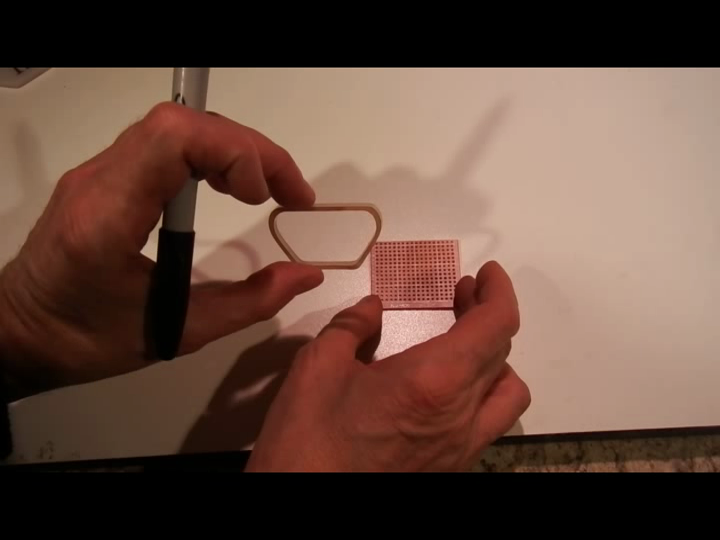
2Step 2
Cut the protoboard blank
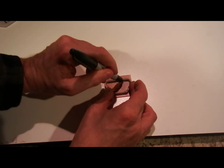
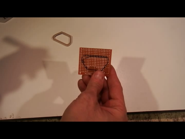
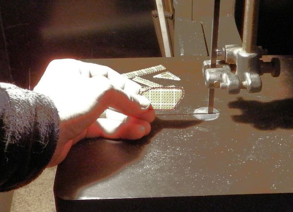
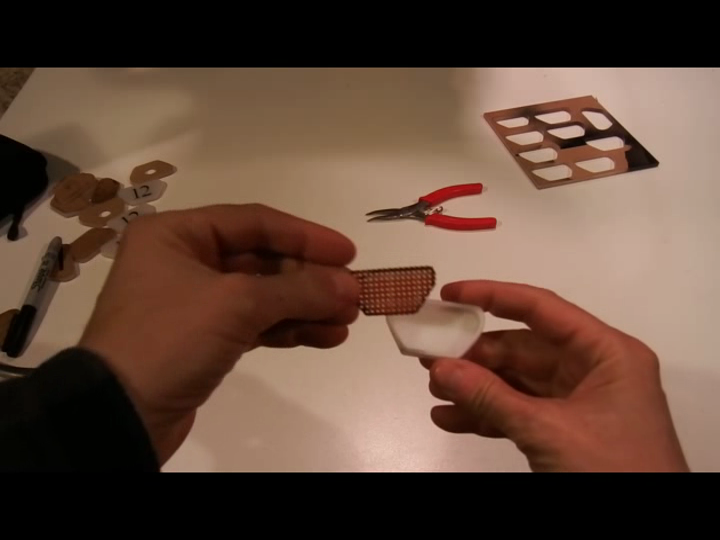
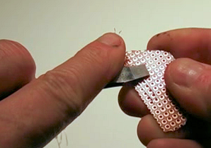
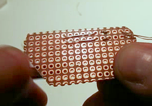
Step 1: Draw the outline of the amulet on the protoboard.
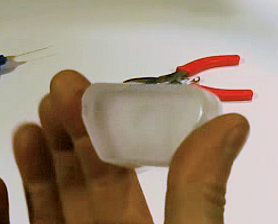
Step 2: Cut the protoboard outline using a nibbler or bandsaw.
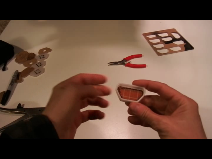
Step 3: Verify the protoboard fits nicely inside the pendant.
-
3Step 3
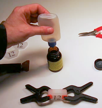
Clamp and glue the amulet
NOTE: Acrylic solvent, methyl-ethyl-chloride, is a neurotoxin that is absorbed through the skin. Be careful!
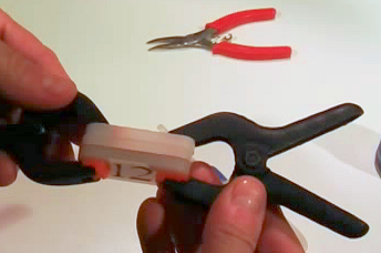
Step 1: Clamp the amulet face and 2 rings together.
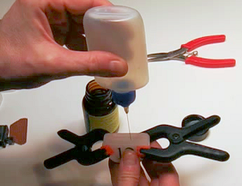
Step 2: Draw a few drops of acrylic solvent into a syringe applicator.
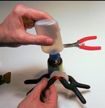
Step 3: Dribble a little solvent on the seam between to layers of acrylic.
The solvent will be drawn into the seam by capillary action, and weld the layers together.
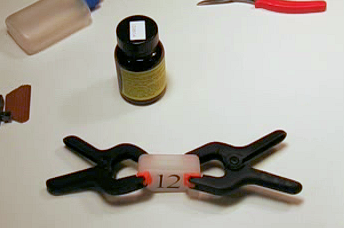
Step 4: Allow welded pieces to dry.
Step 5: Repeat steps 1-4 on the bottom and side seams.
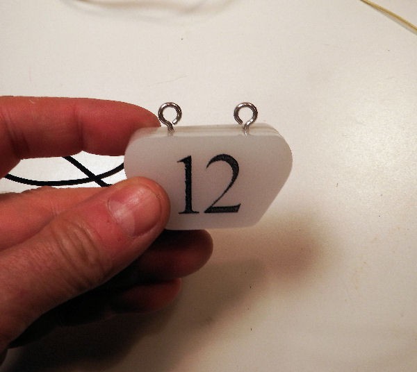
Final results
Optional step 6: Sandpaper the edges to blend the seams together to give the amulet a "single piece" look. -
4Step 4
Mount the LEDs
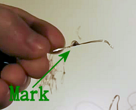
Step 1: Go along the LED chain, marking one side of each LED.
Be sure that all LEDs are marked on the same side.
Step 2: Cut the LED string to make a pile of individual, LEDs, each with a mark.
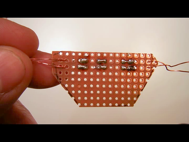
Step 3: Thread the LEDs onto the proto board, with leads from adjacent LEDs in one hole.
Use the marks you made in step 1 to ensure that that all LEDs are wired in parallel.
Step 4: Twist the lead pairs together and cut to about 1/10 inch length.
For reference, the holes on the perfboard are 1/10 inch apart.
Step 5: Use the blade of a screwdriver to flatten the twisted wires against the perfboard.
Step 6: Solder the LEDs together.
Use a hot setting on your soldering iron, and continue heating until the leads wick up the solder.
A note on soldering:
The leads of the LED string are insulated with a polymide film that dissolves when soldered (magnet wire).
Dissolving the insulation requires more heat than a typical connection, so to make good contact keep heating the connection, even after the solder is melted.
You'll notice a change when the insulation dissolves: at first the solder will bead and not flow over the wires, then suddenly the wires will "wick up" the solder.
You may also see a small puff of smoke, indicating that the insulation has burned away.
Step 7: Solder the LEDs in rows and connect the rows in parallel.
Leave 1 set of leads unconnected for now.
(One of my LEDs failed, but the amulet is plenty bright so I'm not going to fix it.)
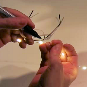
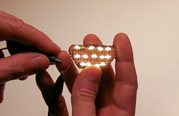
Step 8: Do a quick test with the original battery pack to make sure everything works.
-
5Step 5
Amulet wiring
Note: The wires typically used for an electronics project will not work in a costume!
Typical project wires can only be bent a couple of times before breaking. They are not made to withstand the constant (even gentle) bending and flexing that happens as the wearer moves about.
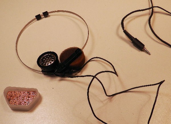
Headphone and ear-bud wires are made to withstand bending and flexing: the insulation is rubbery, and the wires are braided along with cloth tubes and flexible threads that help keep breakage to a minumum.
Don't cut corners by using cheap hook-up wire for the amulet. Use the wires from an old set of headphones or ear-buds to connect the amulet to the control module.
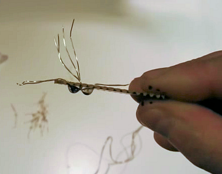
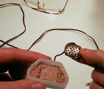
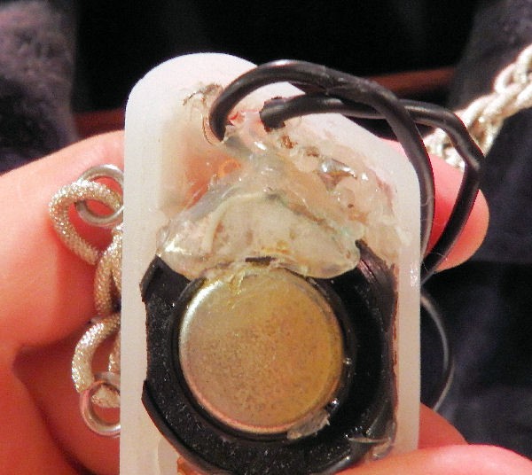
Step 1: Take the headphones apart, discard everything except the cord and speakers.
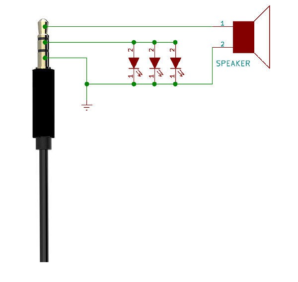
Identify the speaker that connects to the TIP of the stereo connector (see schematic below).
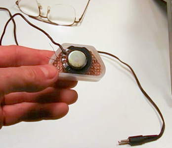
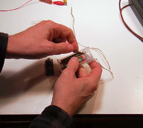
Step 2: Place the speaker inside the amulet, and tack it in place with hot glue.
Only use a little glue at this point.
(Note: Tape insulating the LED connections from the metal speaker grill.)
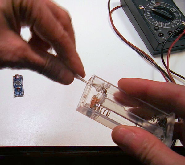
Step 3: Test the amulet! Make sure everything still works.
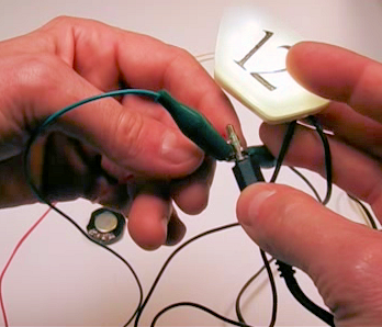
Use the battery pack from the LED string to test the LEDs.
Brushing the battery pack leads against the stereo tip should cause the speaker in the amulet to crackle.
Step 4: If everything seems to work, remove the 2nd speaker and connect its cord to the LED string.
Be sure to get the polarity correct: touching the POSITIVE lead of the battery to the MIDDLE ring of the stereo plug (and negative to ground) should light the LEDs.
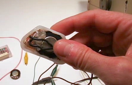
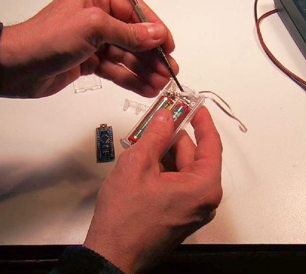
Step 5: Fill the amulet with hot glue to make a strain relief and keep everything in place.
Note: Be sure the amulet works beforehand, you cannot undo this step
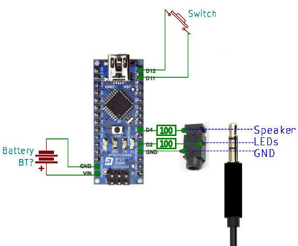
The Amulet Schematic
This is how the amulet connects to the headphone wires.
Click on the image for a better view.
-
6Step 6
Attach hooks and chain
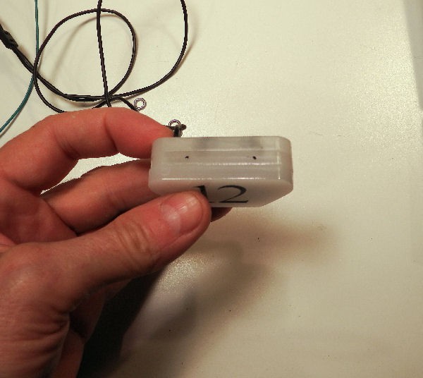
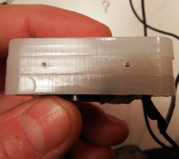
Step 1: On the top of the amulet, mark the hook locations.
Step 2: Using a soldering iron or heated needle, put a divot in the hook marks.
The divot prevents the drill bit from "skating" on the smooth surface.
Step 3: Drill two small holes and install the hooks.
-
7Step 7
Remove the battery pack resistor, install lithium cells
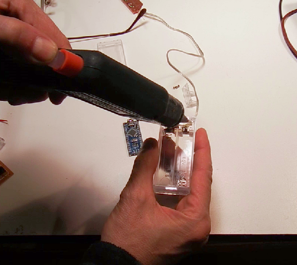
Step 1: Remove the top piece of the battery pack.
Step 2: Without breaking the switch or battery contacts, carefully cut away the current limiting resistor and LED lead wires.
Clip and discard the resistor.
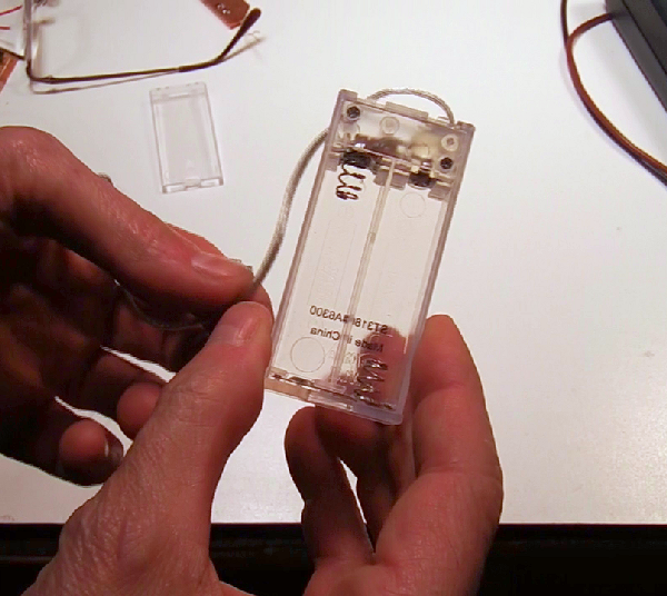
Step 3: Thread the LED lead wires back into the pack, and resolder.
Step 4: Add some hot glue to act as strain relief
Step 5: And replace the top piece of the battery pack.
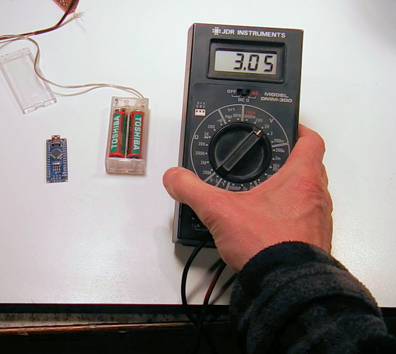
Step 6: Two normal AA batteries generates about 3 volts, which isn't enough to run the Arduino or the LEDs.
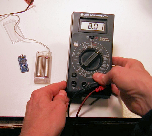
Replace the batteries with 2 AA Lithium cells, to make an 8 volt battery pack.
Eight volts is plenty to run the arduino nano and LEDs.
-
8Step 8
Build the control pack
This is the wiring schematic for the control box.
Click on the image for a closer view.
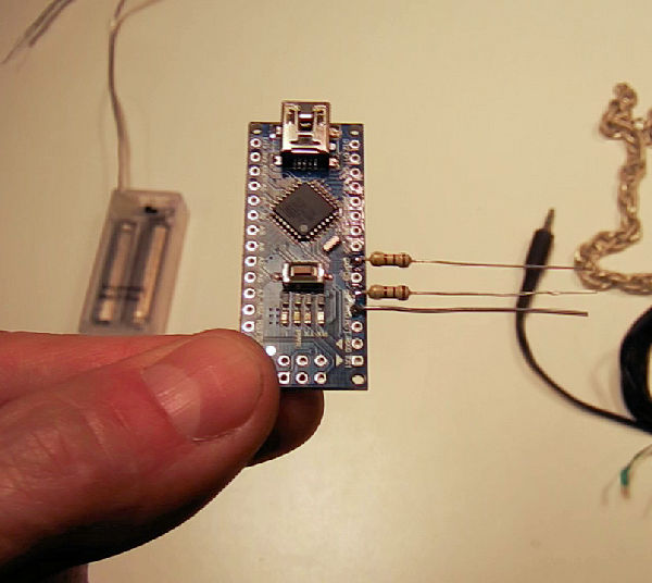
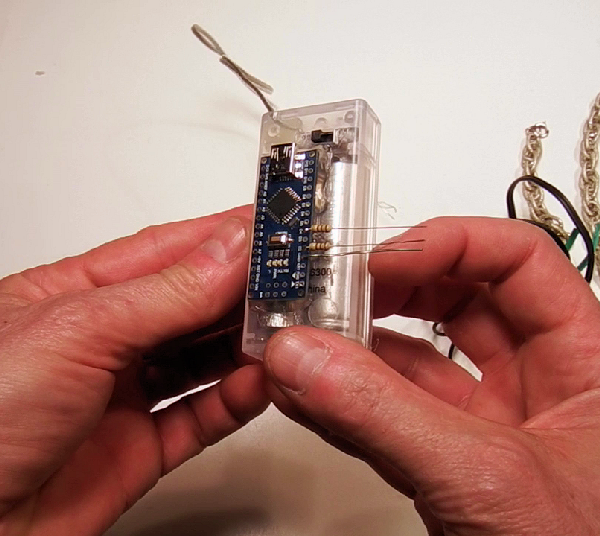
Step 1: Solder a bare lead to GND, and 100 ohm resistors to pins D2 and D4.
(D3 is unused so that D2 and D4 line up with the leads on the stereo jack.)
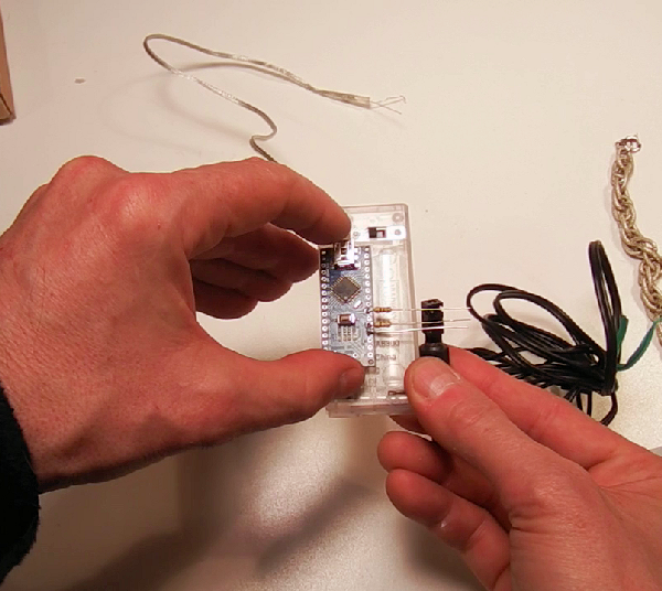
Step 2: With the stereo jack on the stereo plug, measure where the micro should be on the battery pack.
The GND, D2, and D4 leads should line up with the stereo jack leads.
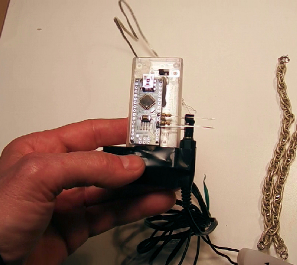
Step 3: Tack the nano to the battery pack.
Don't use a lot of glue at this point.
Don't glue over the pins that are yet to be soldered (see schematic).
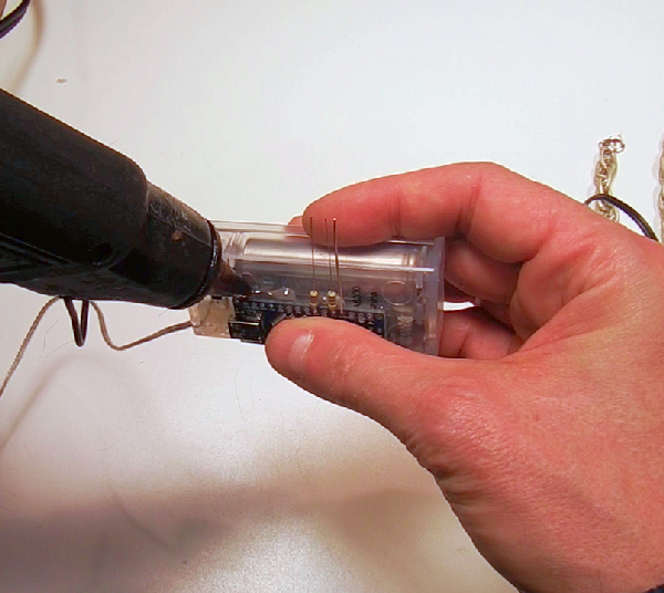
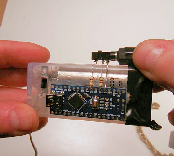
Step 4: Using tape to hold the stereo plug in place, solder the leads from the nano to the stereo jack.
Step 5: Entomb the stereo jack with hot glue.
Use lots of glue, but keep the plug hole clear.
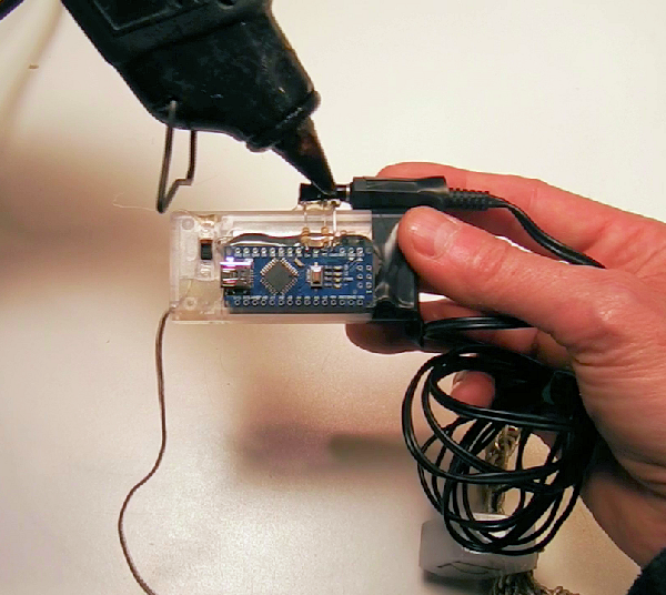
Step 6: Trim the battery leads to length, and solder the positive lead to Vin, and negative lead to GND on the micro.
Then hot glue the battery leads to the case.
-
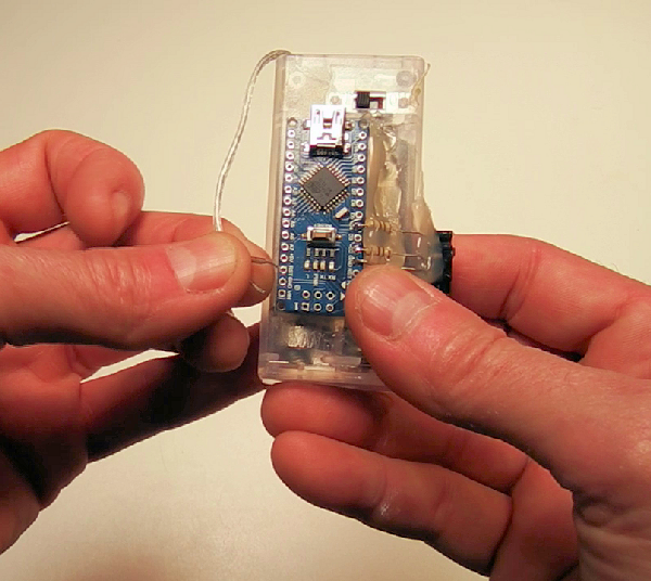
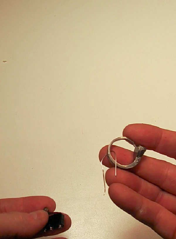
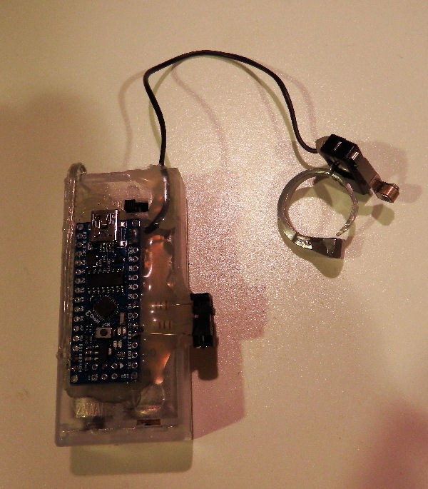
9Step 9
Build the control switch
Step 1: Thread a short piece of wire through the ring and the switch.
Step 2: Twist the wire until the switch is solid against the ring.
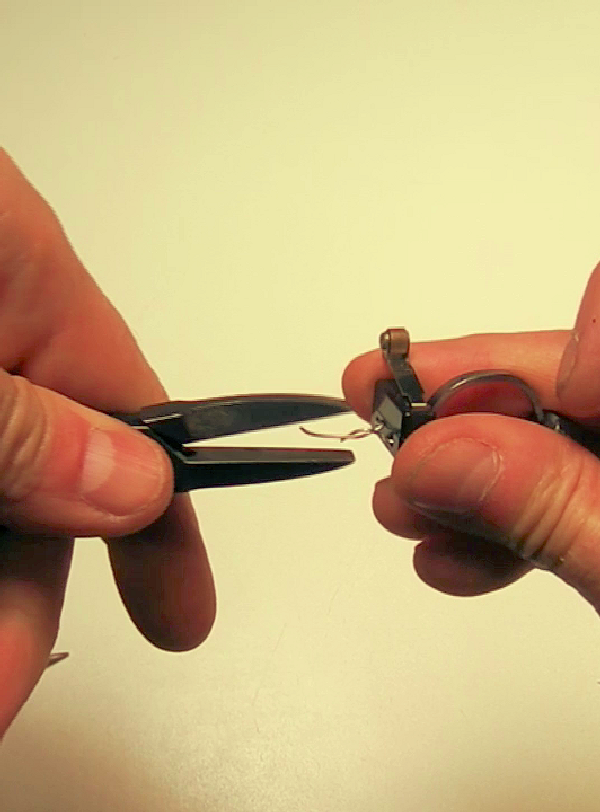
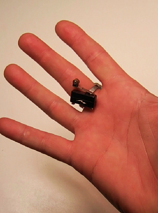
Step 3: Test it for fit and comfort.
Step 4: Connect/solder the switch to D11-D12 on the micro using a spare piece of headphone wire.
Be sure to use headphone or earbud wire. Regular hookup wire will NOT survive this application.
Go over everything with hot glue to keep everything in place, and to act as a strain relief.
Don't forget the switch - that needs a strain relief also!
-
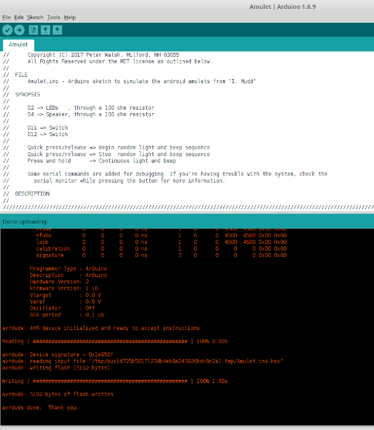
10Step 10
Program the micro
Arduino Nanos come pre-loaded with the Arduino bootloader.
The amulet software is a single file sketch, and should compile and load with no issues.
It uses no external libraries.
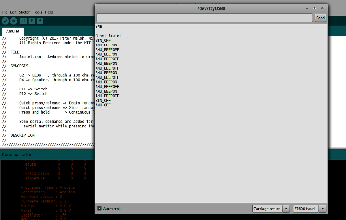
If you have trouble, check the serial monitor.
The amulet controller prints the state changes as they happen, to help you debug the system.
The code is well commented - it should be easy to figure out what's going on
Everything is parameterized up top, in case you need to change the pin assignments or something.
Norman, Coordinate
The blinking, bleeping amulet from that Star Trek TOS episode.


Discussions
Become a Hackaday.io Member
Create an account to leave a comment. Already have an account? Log In.