 EjaadTech
the project started on a small breadboard on an AVR Dev board I had which used AVR ATMEGA32
then moved to a proper breadboard with ATMEGA8 before finally going to the PCB..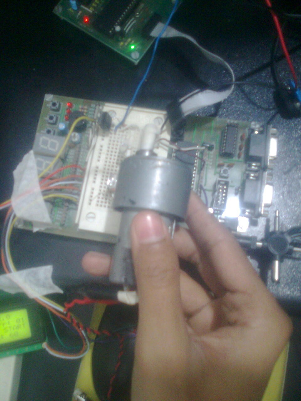
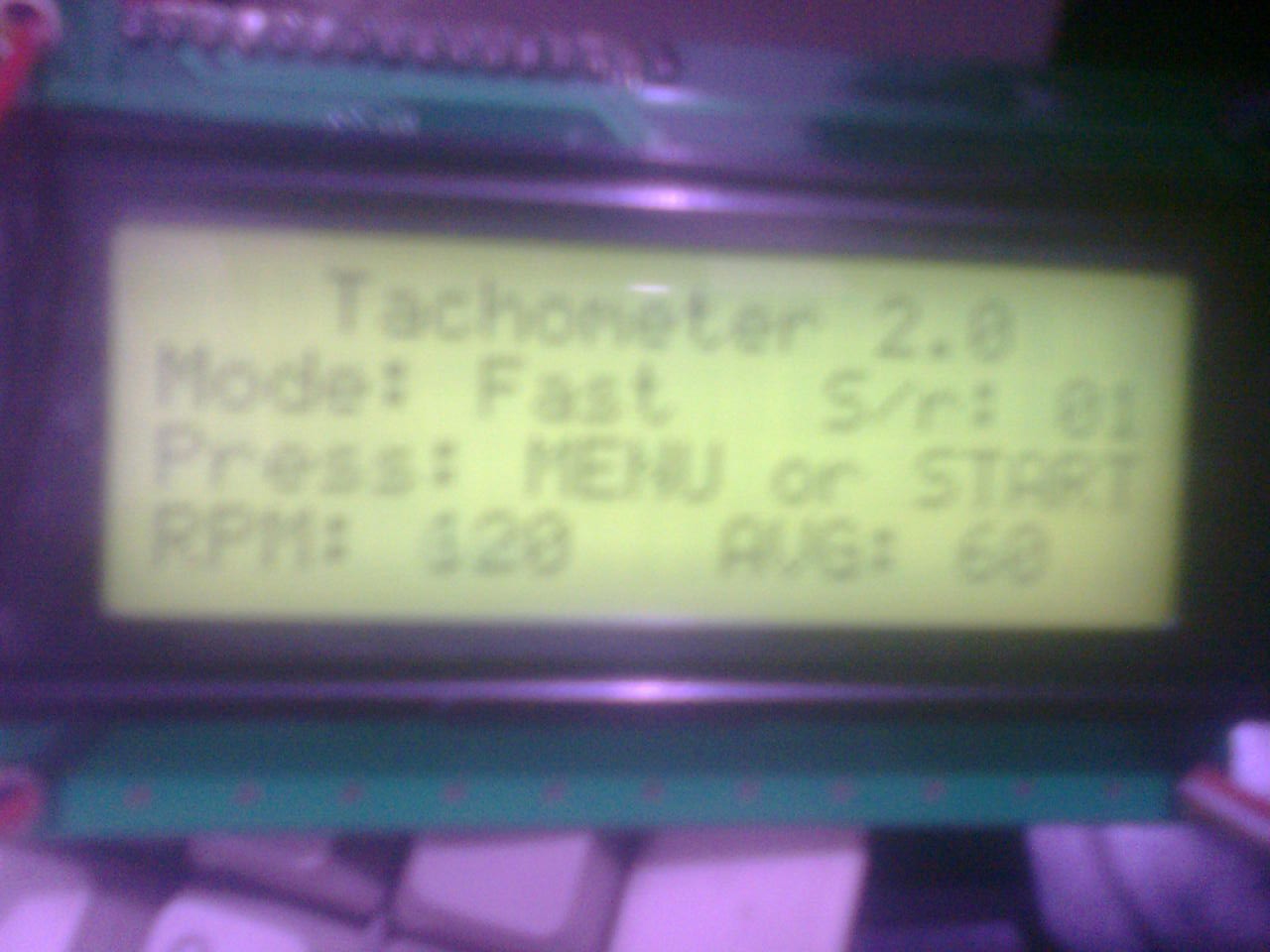
the first test with a tape on a motor and looking at the LCD for results..
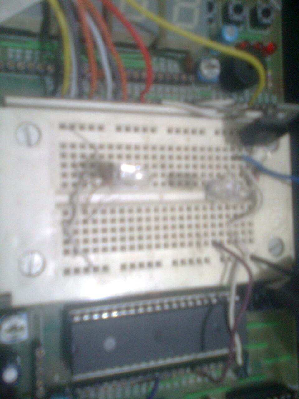 the first simplest sensor, a pass-through...
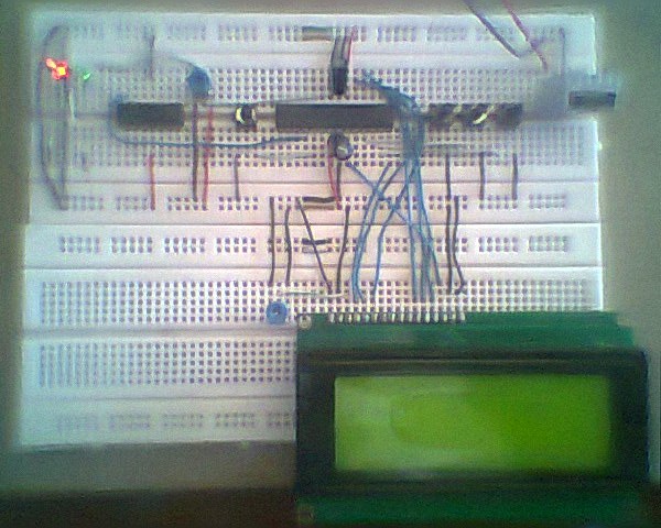
the final breadboard, the images are old and from a very cheap camera.. :) at the right is the 7805 with a heatsink, then the 3 buttons for settings etc, then the AVR ATMEGA8 and finally the OPamp IC so I dont need to do ADC on the sensor, working as a comparator, the opamp provides a simple square wave out to the AVR, which is put on the interrupt pin, as I recall..
Discussions
Become a Hackaday.io Member
Create an account to leave a comment. Already have an account? Log In.