Paul works with three omniwheels driving a ball underneath. He has an IMU (MPU-6050) that provides two angles in x and z direction. These two panes are considered separately. The angle is input of a PID controller that delivers a correction speed in the same pane. This speed is converted into a movement of each omniwheel by use of inverse kinematics.
So, most complex parts of Paul are two things:
1. Kinematics, i.e. having a to-be speed of the bot, how do you compute the speed of each omniwheel?
2. Balance Control, i.e. depending on the two angles against the perpendicular axis the IMU provides, how do you compute the compensation speed in x and ?
Additionally, there is three PWM breakout for the blinking LEDs (everyone likes blinking LEDs!) and an interface to the text2speed module Emic-2 (that's the one Steven Hawkins is using).
The overall components are connected together like this:
Kinematics
This is about computing the angular speed of a wheel out of the speed in x and y direction.
I do not list the boring maths here, if you are really interested please check the Kinematics Computation Excel. The outcome of a tough weekend is this:
On the left side are the angular speed of the omniwheels 1-3. rw is the radius of one omniwheel, rb is the radius of the ball. θ is the angle of motor's axis against the perpendicular axisp. RT is the transposed rotation matrix that is given by the two angles φx and φy coming from the IMU:

vx and vy is the speed in x and y direction, ωbz is the angular speed of the bot when Paul turns at the same position. All this together is implemented in Kinematics.cpp
Micro-wise I use two ATmega 644, one for running the balancing loop, and the other receiving moving commands from the remote via xbee and controlling the LEDs and speed. Since the AVR is a bit too weak to run a control loop with 100Hz, I use fixed point arithmentics instead of floats, which makes the code hard to read.
Control Loop
The control loop is a slightly adapted PID controller which has as parameters:
- body position, body speed, body acceleration,
- head position, head speed, head acceleration.
- to lean into curves, the angular speed is used to compensate the centripedal force
All these parameters are computed out of the IMUs values, multiplied with a certain weight and added (implemented in BotController.cpp). Before that, the IMU's values are filtered with a Kalman filter to avoid sensor noise by fusing the gyro values with g-force sensor values (Implemented in IMU Component).
Before you ask: Yes, I manually tuned the PID parameters. I tried the academic way, but it did not work out very well.
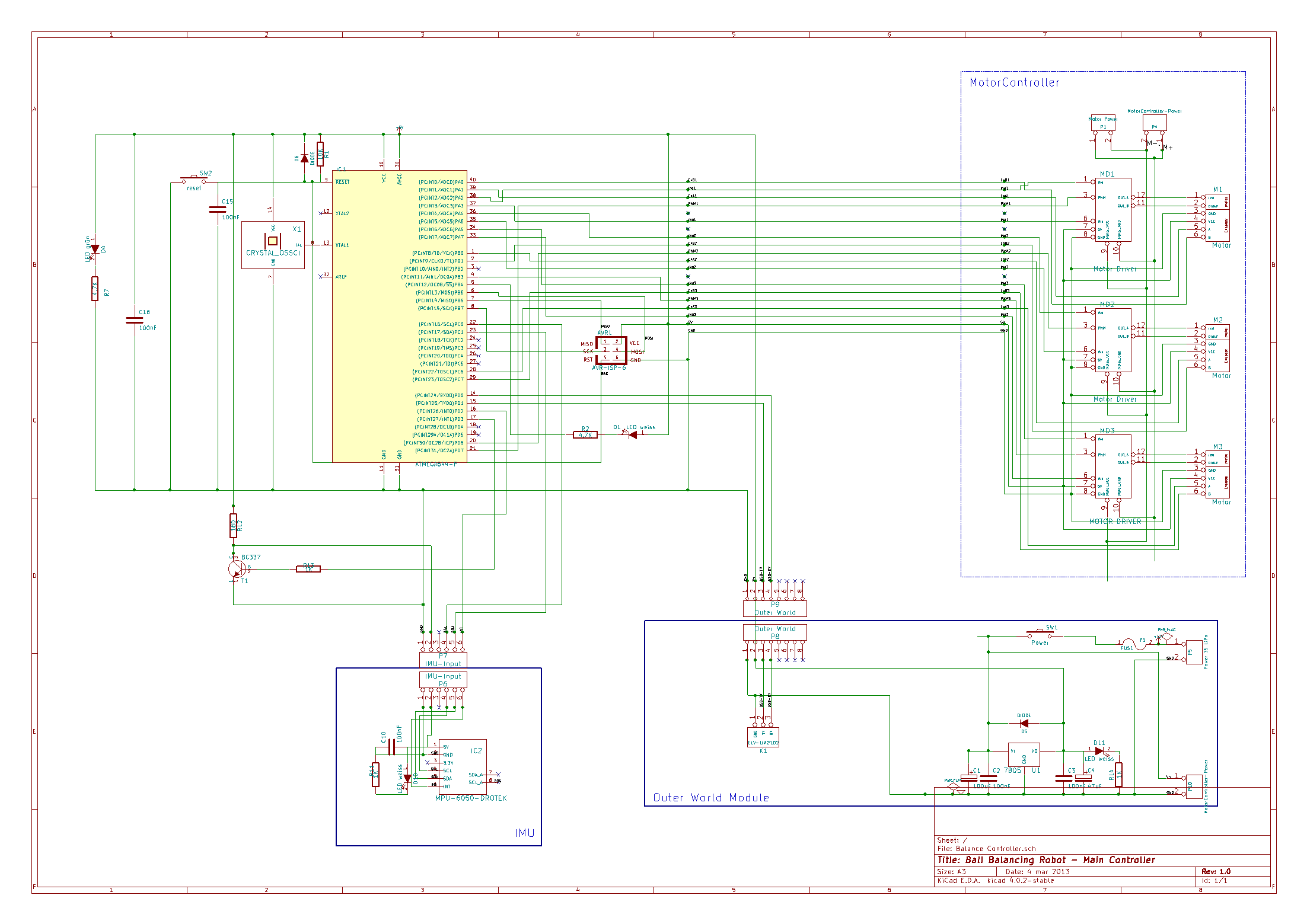
Schematics
Schematics (KiCad) is here . Main uC is sampling the IMU, executing the PID controller and sending the result to the motor drivers (H-Bridges):
Construction
The dimensions of the motors, omni wheels and the balls are denoted here:

I did not use a CAD programme but drew all the mechanical parts in
powerpoint (really uncool, I know). I glued the printouts on plywood and used a scroll saw to get the pieces. This is the
powerpoint file with construction shapes.
 Jochen Alt




 Ghani Lawal
 Danny FR
 Artur Majtczak
 Paul Gould
Dear Jochen Alt
I'm from Brazil. I made a ballbot as well. Some videos about my ballbot:
https://drive.google.com/file/d/1nWU0XHk-8-4tK-WwWBTTzzUdiljSq0SM/view?usp=sharing
https://drive.google.com/file/d/1wf0ar_ykmmo4MJeqreep7MpMU-sA6eoK/view?usp=sharing
(yaw test)
It works very well. I'm trying translation X and Y axis, but not sucess. Can you help me ?
See this video https://www.youtube.com/watch?v=iHOtxM241AA He made a amazing ballbot.
E-mail: pedrophj@yahoo.com.br
Thank you so much