Arduino based - Air Source Heat Pump
Replacement of original Chinese microcontroller in order to fix and increase an efficiency of the heating system for a house.
Replacement of original Chinese microcontroller in order to fix and increase an efficiency of the heating system for a house.
To make the experience fit your profile, pick a username and tell us what interests you.
We found and based on your interests.
HeatPump.fzzFritzing circuit schemefzz - 80.79 kB - 02/26/2017 at 13:27 |
|
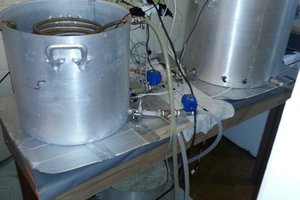
I recently installed an air-source heat pump for water heating system. Usually, they cost around 10000 EUR/USD, but I got used and Chinese made one for just 500 EUR/USD. As you probably know you should never buy used heat-pump, fridge etc., just because owner bought a new one. Usually, they do not break often and if they do or they have some other problem, only then the owner would sell it (if he is evil..). Anyway, I did not consider this and was willing to risk. Also important to notice is that I am living in northern part of Europe (Latvia), so in winters we get temperatures below 15-20°C / -5°F . Air source heat pump might not be the most effective, but it is more effective than for example shallow ground (2m) heat pump that would freeze up the whole yard till summer. Maybe deep bore (+100m) heat pump would be more effective + much more expensive.
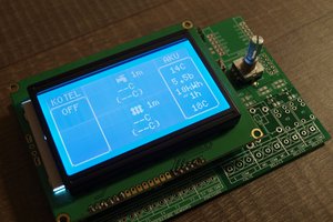
Now when we fixed minor problems, like replacing water circulation pump and some leaks in freon system, everything was working fine, but as soon as the ambient temperature was close to water freezing point -5°C till 5°C Heat pump's radiator began to froze-up. As I tracked down the problem I understood that Chinese microcontroller improperly executed defrost cycles. It almost did not execute them at all. Also as this manufacturer do not provide any information about the microcontroller, I had to create my own control panel/microcontroller for the whole system.
After implementing new control panel, I can control every aspect of heat-pump using PC and now it is also much more economic than before and do not build-up ice.
Also, I added an external sensor ("robot eye") that is tracking how much ice has been build upon external radiator/evaporator.
In order to explain how heat-pump works I created interactive animation on my website here: http://yellowrobot.xyz/heat-pump-diag/index.html
I also recommend watching my video on youtube about this yellowrobot.xyz project:
The heat pump uses a physical process of convection to transfer heat using pressurization and de-pressurization. It works exactly like a fridge but its result is heat not cold.
Basically, at winter time, normal operation of an air-source heat pump is following:
My heat pump that was designed in China used ambient temperature and simple timer to initiate defrost cycle/mode. Unfortunately, they did not manufacture it for the north European climate. Here in Latvia, during winter when outside temperatures are around +5 °C till -5°C we have very moist air that causes huge ice buildup on evaporator/radiator. Interestingly that this heat pump worked much better at temperatures -15°C till -20°C when the air is dry and cold. During this time I had no problems with it and it produced very good efficiency results.
I tried many things to diagnose problems and to hack it, but it was not possible to re-program microcontroller, so I had to devise a plan to replace it all together.
Otherwise, I had to manually wire up defrost mode hack every time heat pump was totally frozen. It was at least 2 times a day + electricity bill was awful when outside temperature was +5 °C till -5°C

All source code and Fritzig scheme of circuit is available here on GitHub:
https://github.com/evaldsurtans/heat-pump-arduino-...
Robot "eye"
In order to detect ice buildup, I used an idea from line follower robots that have IR sensor for detecting black line on the surface against a white background. As ice is more or less white when formed on evaporator/radiator I can use this sensor's analog value to discriminate when it should initiate defrost mode/cycle. IR line detecting sensor is just IR diode emitting IR light and other IR diode absorbing reflected light of surface. To secure it from water exposure I used layers of hot glue.
Relays
Luckily inside heat pump's cover, I found circuit diagram that helped me to understand the operation of the system. The heat pump actually uses chained realys where 220V 6A AC relays at controller board trigger next huge 220V 16A AC relay relay downstream. These huge relays then start the compressor, fan, internal heater, valve solenoids, etc. As these are quite powerful they create EMI (Electro-Magnetic Interference), so it is essential to separate them as much as possible from microcontroller circuit. In the end, I used a seperate power source for first layer of relays (220V 6A AC) and triggered them using NPN transistors and Optron/Opto-couplers or Opto-transistors. These then created optical connection between relays and microcontroller. Otherwise there are a lot of problems that might occur as I described them in next step of this instructable.
Microcontroller
As for microcontroller I used original Arduino Mega 2560. I also tried Chinese clone Arduino Mega 1280, but it caused chaos beyond imagination that I described in next step. Original Arduino Mega 2560 works very stable and robust.
PCB
As this is the only prototype I did not bother to produce custom made PCB, but instead, I used dotted soldering plate on which I created as many paths as possible. For other connections, I used jumper wires that are useful for quick testing of ideas and changes in design. If someone wants to replicate this I would advise to create custom PCB to avoid spaghetti of wires.
Temperature sensors
For measuring temperature I used pump's built-in temperature probes that are just dead simple thermo-resistors. I experimentally found its properties using linear regression, because there were no indications of its type. For more precise temperature measures I used also one wire sensors DS18B20 (coupled with 4.7K resistor).
Components needed
Code
Progam is the most important part of the project/brains. Main features of code are:
For programming Arduino I would advise using Visual Studio 2015 Community Edition and Visual Micro plugin that is fantastic for coding and debugging http://www.visualmicro.com/ . If you are skeptical and used to Arduino IDE you should try Visual Studio C/C++ auto-completion features. Also JetBrains plugin for C/C++ auto-completion is wonderful https://blog.jetbrains.com/dotnet/tag/resharper-c/
Useful code snippets from whole code on github:
SD card breakout
#include "SD.h"

void setup()
{
	if (!SD.begin())
	{
		Serial.println("SD failed!");

	}
	else
	{
		Serial.println("SD connected.");
	}
}

void testSD()
{
	//if(SD.exists(fileNameHistory))
	// SD.remove(fileNameHistory);

	File myFile = SD.open(F("test2.txt"), FILE_WRITE); // if the file opened okay, write to it:
			if (myFile) {
				Serial.print(F("Writing to test2.txt..."));
				myFile.println(get_full_datetime());
				// close the file:
				myFile.close();
				Serial.println(F("done."));
			}
			else {
				// if the file didn't open, print an error:
				Serial.println(F("error opening test.txt"));
			}

		myFile = SD.open(F("test2.txt"));
			if (myFile) {
				Serial.println(F("test2.txt:"));
				// read from the file until there's nothing else in it:
				while (myFile.available()) {
					Serial.write(myFile.read());

					wdt_reset(); //tell watchdog that you are still alive (must call in every <8 sec)<br>
				}
				// close the file:
				myFile.close();
			}
			else {
				// if the file didn't open, print an error:
				Serial.println(F("error opening test.txt"));
			}
}
Watchdog timer
#include "avr/wdt.h"

wdt_enable(WDTO_8S); //restart arduino if there are no response in 8 sec

wdt_reset(); //tell watchdog that you are still alive (must call in every <8 sec)

void loop()
{

//do work

wdt_reset();

}
Timer interrupts for keeping precise time in parallel of other code
http://astro.neutral.org/arduino/arduino-pwm-pins-...
#include "TimerThree.h"<br>
Timer3.initialize(500000);         // initialize timer1, and set a 1/2 second period
Timer3.pwm(PIN_TIMER_3, 512);                // setup pwm on pin 9, 50% duty cycle
Timer3.attachInterrupt(timer_callback);  // attaches callback() as a timer overflow interrupt
Reading voltage level from internal reference
long readVcc() {
// Read 1.1V reference against AVcc

// set the reference to Vcc and the measurement to the internal 1.1V reference

#if defined(__AVR_ATmega32U4__) || defined(__AVR_ATmega1280__) || defined(__AVR_ATmega2560__)     ADMUX = _BV(REFS0) | _BV(MUX4) | _BV(MUX3) | _BV(MUX2) | _BV(MUX1);

#elif defined (__AVR_ATtiny24__) || defined(__AVR_ATtiny44__) || defined(__AVR_ATtiny84__)     ADMUX = _BV(MUX5) | _BV(MUX0);

#elif defined (__AVR_ATtiny25__) || defined(__AVR_ATtiny45__) || defined(__AVR_ATtiny85__)     ADMUX = _BV(MUX3) | _BV(MUX2);

#else     ADMUX = _BV(REFS0) | _BV(MUX3) | _BV(MUX2) | _BV(MUX1);

#endif  <br>delay(2); // Wait for Vref to settle   <br>ADCSRA |= _BV(ADSC); // Start conversion   <br>while (bit_is_set(ADCSRA,ADSC)); // measuring

uint8_t low  = ADCL; // must read ADCL first - it then locks ADCH     uint8_t high = ADCH; // unlocks both<br>long result = (high<<8) | low;

result = 1125300L / result; // Calculate Vcc (in mV); 1125300 = 1.1*1023*1000   <br>return result; // Vcc in millivolts

}
In the end, I just had to replace controller panel and hook up all cables and start testing it.
Create an account to leave a comment. Already have an account? Log In.
Become a member to follow this project and never miss any updates

 renatomsteiner
 Jiří Praus
 Anteneh Gashaw
 Non-ICE
Hi, I like what you are doing here, I have also developed a heat pump controller however mine uses an ESP8266 so all the interface and control is done via a web page. I like the idea of ir to detect frost, I´m working on a different principle using BMP sensors to detect pressure differences between outside pressure and the pressure behind the fan.
I had a quick look through your code and noticed one thing, when you run your defrost code you leave almost no time between switching the compressor off and back on again. Have you had this working as in my experience you should leave up to a minute between switch off and switch on or you may end up with rotor lockup as the pressure across the compressor will not have equalised.