*YMMV
Spent several hours testing the SDRAM adapter board. Haven't had a chance to play with the I2S stereo DAC yet.
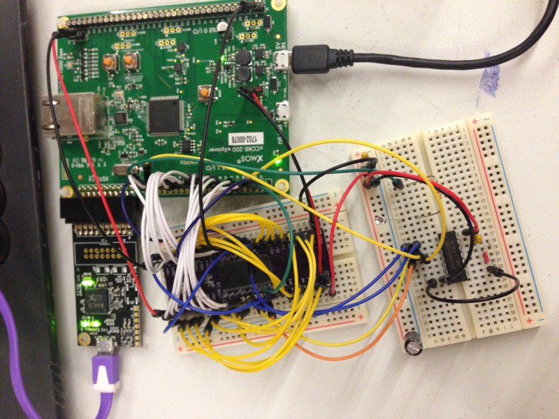
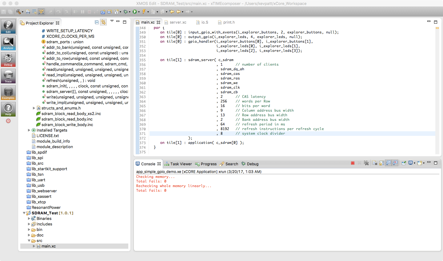
I did get the SDRAM to work with my XCORE-200 explorerKIT. However, it's definitely erratic. I'm able to write pseudorandom values to the entire 32 MB, and read them back successfully, but not 100% of the time, more like 90% of the time. My suspicion is that using a rats nest of jumper wires to a breadboard is not adequate with respect to the signal integrity required. But the library works, and I'm satisfied I know how to interface an SDRAM IC to the xCore.
Here are my thoughts on the "reliability" issues. Please note that I'm not complaining about XMOS :). I realize the pictured setup is a completely hacked-up arrangement that is probably way out of spec, and it's probably a miracle I got it to work at all. :P The following thoughts are here just for anyone who is curious or might have some ideas of their own to share.
Possible problems:
- Maybe there's a subtle timing or setup compatibility issue with the Micron SDRAM (I'm using part number MT48LC16M16A2TG-6A:G) See here. I don't have any ISSI parts, but I may order one and try it on another copy of the adapter board.
- As a result of reading the above thread, I ended up using the lib_sdram master branch from this git repo. It seems to be the most up-to-date. (I had trouble with the lib_sdram installed by xTIMEcomposer, but perhaps I gave up too soon?)
- I may have insufficient ground connections between the SDRAM adapter board and the explorerKIT. I need to populate the rest of the Tile I/O ground pads on the explorerKIT...
- All Vss connections on the adapter board are tied to a common ground plane, and all Vdd connections are tied to a common 3v3 rail. The SDRAM is decoupled by two 0.1µF and two 1µF MLCC X7R caps on the adapter board. Maybe this is not enough.
- Noise picked up by the jumper wires, or signal issues caused by inductance, excess capacitance, lack of impedance control on these lines, or the breadboard stubs. I need to check this on my scope. Perhaps I have bad skew, reflections, ringing, and/or overshoot...
- I don't have an ultra-fast NOR gate handy, so I'm using a 74AHC02. It's rated about 6ns at 3v3, compared to the 2ns of the 74LVC02 part recommended by XMOS, so about 1/3 the speed. This alone could be the source of all my problems, but I would think it would become irrelevant at slower clock dividers... But I'll order an LVC part and try.
Oddly enough, I get pretty good results at certain clock dividers. I can run the pictured setup at div=8 (31.5 MHz), but no faster. HOWEVER, going slower (div=9, 10, etc.) doesn't seem to help! I even tried running at div=20 and 25, but everything slower is about 10-20% "reliable", compared to about 90% at div=8. I tried changing CAS to various numbers, no help. 2 works best at div=8, and 3 is marginally better at slower clocks... I also messed with "#define N (1)" in io.S, but changing it to 0 makes things almost totally unusable, even at very slow clocks (div=20, etc.).
Perhaps the most nagging issue is that I feel like I should be able to get this to work reliably at a slower speed (say 5 or 10 MHz). Perhaps there are some tweaks that I need to make to the library that I'm not aware of?
So, barring some miraculous insight that I'm yet to have, I'll probably end up designing a new (4-layer) board that incorporates both the SDRAM IC and an XMOS mcu on the same board, with impedance controlled traces, etc. Definitely a learning experience.


 Kevin H. Patterson
Discussions
Become a Hackaday.io Member
Create an account to leave a comment. Already have an account? Log In.
Howdy! Haven't read the details too thoroughly, yet... but you might try using a shielded-cable for the sdram-clock... The other signals aren't so important, since they all change *opposite* the clock, but when they all change it can be coupled into the clock-line, unless it's shielded. I've had good luck with the cables that lead to internal wifi antennas, also some higher-quality between-board video cables from VCRs.
Are you sure? yes | no