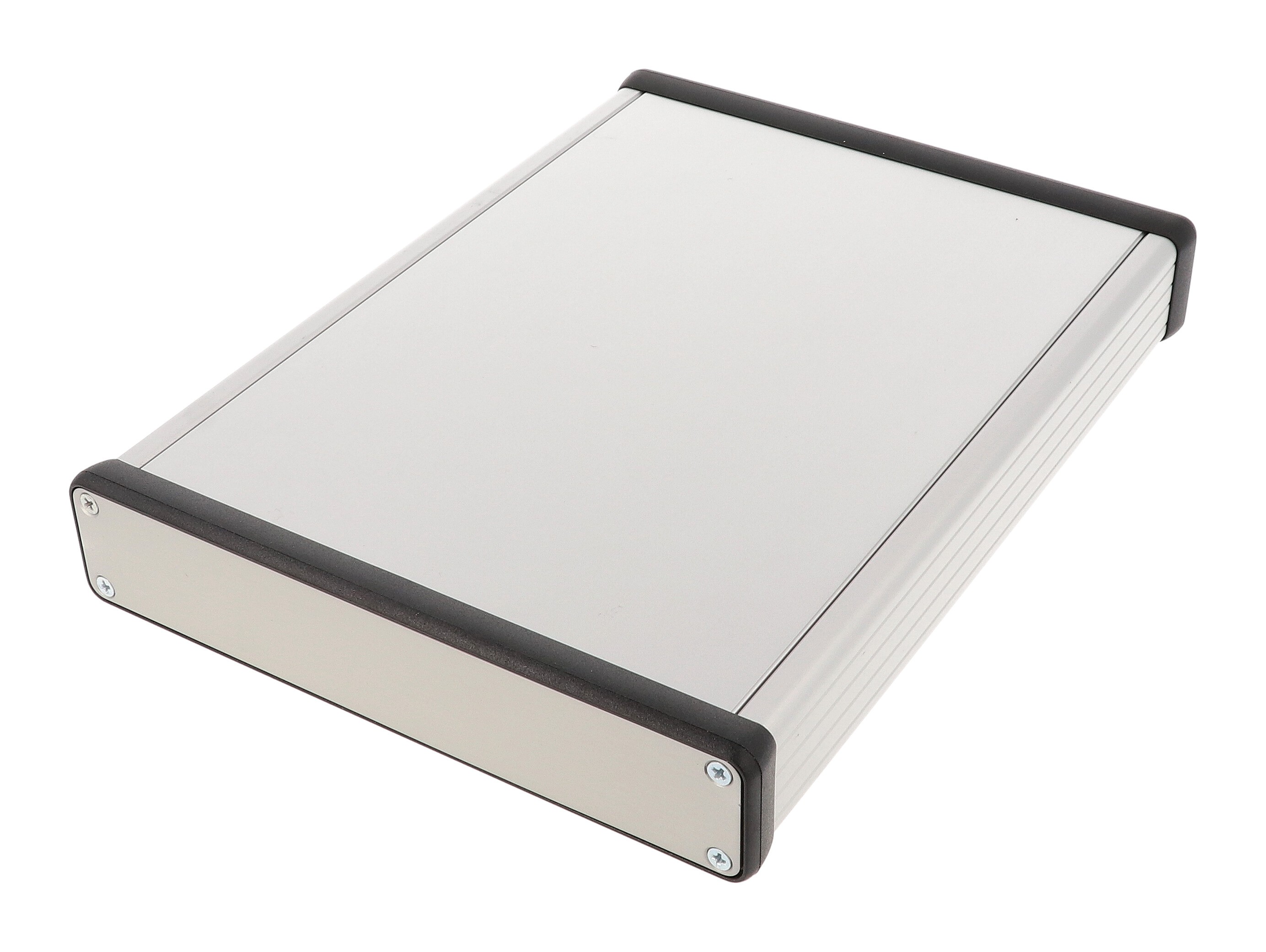
A serious instrument like the Haasoscope Pro needs a good enclosure, to protect the expensive things inside, keep the board from shorting out on other things on your desk, and keep out RF interference. Plus it just looks good and professional!
I decided to go with an extruded aluminum enclosure. It's cheap, easy, works great, and looks pretty good. This one from Hammond is the perfect size for the project, and only ~$30.

There's nice rails on the inside between which you can slide a PCB (or even multiple PCBs). It took a little experimentation to find just the right size to make the PCB so it fits snug.
The only work is in getting just the right openings in the front and back panels so the connectors fit. At first I thought about having aluminum panels laser cut. But how do you get the text printed on for the labels? A much easier way is to just to make PCBs for the panels! They can have whatever shaped cutouts you want, nice text printed on, and even come in cool colors. You could even have active components on the panels, like LEDs, but this would require some connectors and cables for power and communication with the main board.

To retain the RF shielding, a GND plane is added on the back of each panel.
One last worry is heat. The Haasoscope Pro uses about 6W while it's active, about 3W of which is coming from the ADC, 1W from the FPGA, 1W from amplifiers and other random stuff, and 1W from power supply inefficiencies. The aluminum enclosure can easily dissipate this amount of power with minimal temperature rise inside, thanks to its large surface area. But 20x20x10mm aluminum heatsinks are added on the ADC and FPGA with thermal tape, since they're small and generate most of the heat. A small 40x40x10mm 5V 60mA fan is also glued to the inside of the top of the case and blows onto the ADC (and slightly on the FPGA) when the unit is active.
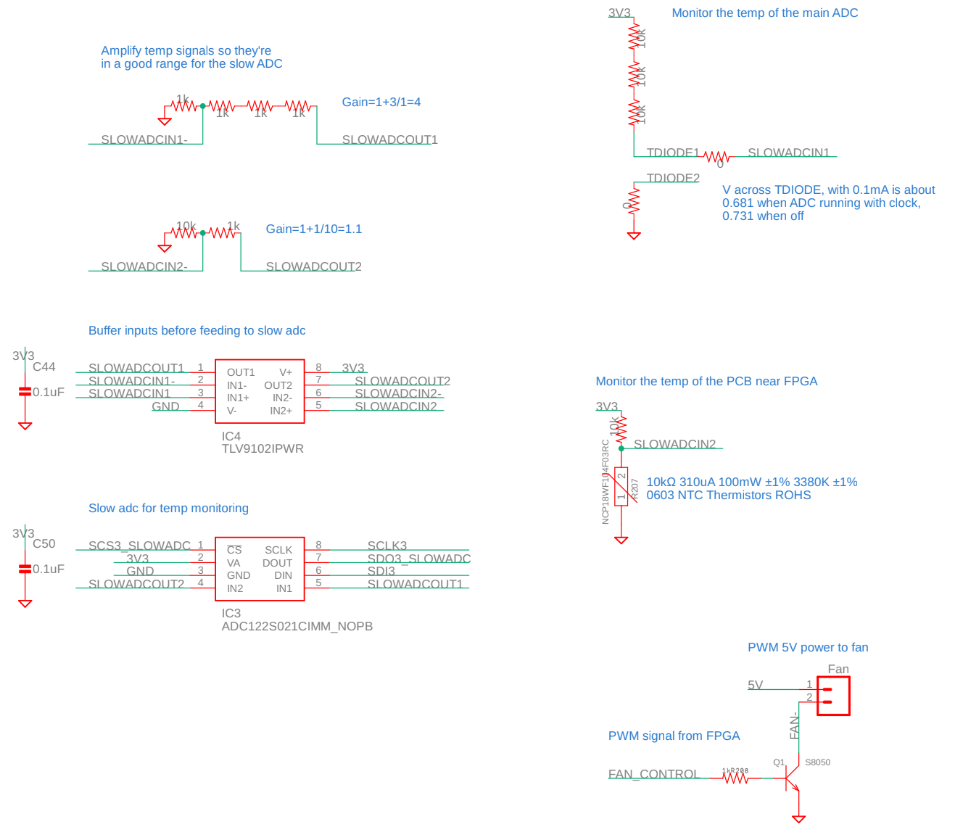
Temperature monitoring is done in two places. The ADC has an internal temperature diode - the voltage across it, measured across two of the ADC pins, goes from about 0.73V when off, to about 0.68V when running, when in series with a 33k resistor. There's also an NTC thermistor on board, which measures the ambient air temperature on the board near the FPGA. These two sensors get put into a slow dual op-amp and slow dual-channel ADC, which gets read out over SPI by the FPGA.

 haas
haas
Discussions
Become a Hackaday.io Member
Create an account to leave a comment. Already have an account? Log In.