ventosus
-
Sensor Breakout Boards Have Arrived
08/27/2014 at 16:38 • 0 commentsBad Timing
Two hours after the Hackaday Price deadline, the sensor breakout boards have finally arrived from OSHPark.
![]()
The respiratory air pressure sensor breakout board:
![]()
The linear hall effect sensor breakout board:
![]()
Reflow Soldering
The solder paste stencils have been laser cut at the local FabLab out of 120um mylar sheets...
![]()
![]()
...and they matched the pads perfectly...
![]()
![]()
...after some solder paste has been applied...
![]()
...and the components have been picked and placed manually...
![]()
...they were baked and were ready to be tried out...
Expressive Valve
The linear hall effect sensor breakout board is mounted at the lower end of the expressive valve build and will measure continuous magnet distance.
![]()
Blow sensor
Two brass tubes with 3mm bore diameter are taped together. One of them is connected to the pressure sensor, the other acts as a bleed.
![]()
-
Normalization and Linearization
08/17/2014 at 09:06 • 0 commentsNormalization of respiratory air pressure values
The raw respirator air pressure ADC readout P we want to transmit from the device to the host must be mapped from the original 12bit ADC range [0,0xFFF] to a normalized floating point range of [0,1]. This is easily accomplished with some precedent calibration of minimal raw ADC readouts of Pmin and Pmax. The formula for nomalized pressure Pn thus is:
![]()
Normalization and Linearization of linear hall effect sensor data
The formula for nomalized magnetic field strength Bn is equivalent to normalized pressure Pn with precedent calibration of minimal raw ADC readouts of Bmin and Bmax and raw magnetic field strength B.
The strength of the magnetic field of a permanent magnet decreases with increasing distance (or decreasing stroke septh) from the sensor. This decrease is non-linear and the equations involved are non-trivial, it depends on the material and form of the permanent magnet. As a general rule, at least a cubic relationship can be assumed.
What we are interested in the end, regarding the signal of the linear hall-effect sensors is not normalized magnetic field strength Bn per se, but normalized stroke depth yn. We thus need to linearize this non-linear signal.
![]()
Nowadays, magnetic fields can be approximated with finite-element calculations, this however is overkill and not practical in realtime on a microcontroller. To approximate the stroke depth of a given magnet from the sensor based on the sensed magnetic field strength at the latter in realtime it is therefore best to do some non-linear curve fitting for the given pair of sensor and magnet before-hand. In realtime, the fitted distance-function is simply applied to the normalized magnetic field strength Bn to get to the normalized stroke depth yn.
The relationship can vary considerably between different types of permanent magnets, we thus need a way to calibrate on-the-fly to different types of permanent magnets. This is done with a five point least squares fit and leads to an analytical solution with the help of some linear algebra. Points 1 and 5 are boundary conditions (0,0) and (1,1), points 2-4 will actually be measured.
![]()
-
The expressive push button (aka E-valve) in real
08/14/2014 at 09:00 • 0 commentsBefore we build all 8 expressive button of the final device, we will do some preliminary experiments with a single standalone unit. In this log entry, we present the component choice for our initial version.
Component choice
We need the expressive button to be responsive and accurate at the same time.
For the accuracy, we thought we would need a heigh enough stroke depth and way of smooth transitioning and theerefore chose a linear ball bearing and cylindrical stainless steel rod. However, the linear ball bearing did not perform as intended, it added a lot of jitter in the movement which was exactly what we wanted to prevent at all costs. We thus converted the linear ball bearing into a sliding bearing, simply by removing the balls. This now works really smooth and as intended.
The responsiveness is achived by sprnig loading the button. The spring parameters were chosen by preliminary tests with a kitchen scale. We thus took our weekest finger (for most people its the smallest one) and sqeeezed the scale with a force that we thought would be still comfortable for prolonged play on the final design. The scale displayed 500g which roughly corresponds to 5N. The stronger the spring, the more responsive the button. But the stronger the spring, the more tiresome it will be to actuate the button, too. A maximal spring force of 5N was a first guess and our initial tests show that it was a good initial guess. The buttons feedback is very prompt.
The lengths of the rod and spring were chosen to have a maximal possible stroke depth of 20mm. The heigher the stroke depth, the easier it will be to tune in to a given position. But the higher the stroke depth, the more impractical the overall play will get, too. 20mm as the maximal stroke depth is a guess what may still be practical. Time will show whether it was a reasonable choice.
At the end of the bolts we will mount the linear hall effect sensor breakout board. The PCBs have not arrived yet, so we can only dry-test the assembly for now.
The Neodymium magnet is just mounted below the collet at the end of the rod. It's exact size will depend on stroke depth and signal amplification. We will know more once have the breakout boards.
Component list
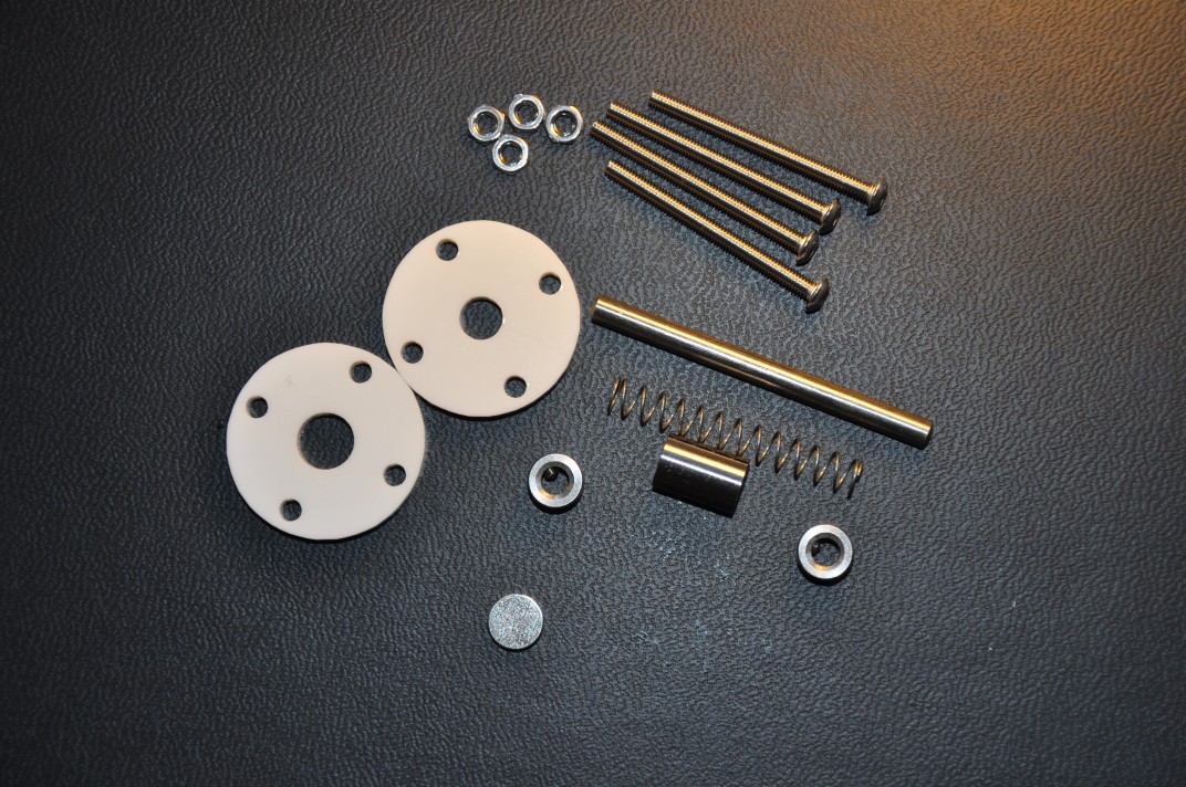
- 1x Slide bearing or linear bearing M4 LM4UU
- 1x Rod M4x50mm DIN 7
- 2x Collet M4 DIN 705 A
- 4x Bolt M3x35mm ISO 7380
- 4x Nut M3 DIN 439
- 1x laser cut acrylic braket with 1x M8 bore, 4x M3 bores (matching the PCB mounting hole spacing)
- 1x laser cut acrylic braket with 1x M6 bore, 4x M3 bored (matching the PCB mounting hole spacing)
- 1x Neodymium cylindrical magnet M8
- 1x compression spring d=0.4mm, D=5,0mm, L=35,8mm, N=14,5, F=5N
Component images
Parts of a single standalone assembly expressive button.
![]()
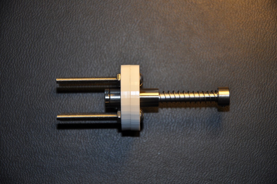
Assembled standalone expressive button:
![]()
Animated GIF of an infinite stroke cycle.
![]()
-
Introducing the Chimaera DSP Unit
08/04/2014 at 09:20 • 0 commentsHow do we get the analog signals from the respiratory pressure sensor and the 8 expressive buttons via the network to a software synthesizer? We need a MCU and PHY, right? We will use one of our designs we already have at hands from an other project: the 'Chimaera DSP Unit'.
Chimaera DSP Unit
It is a mixed-signal board. It uses a 32bit ARM Cortex M4 microcontroller from STMicroelectronics (STM32F303Cx) clocked at 72MHz. Of the available peripherals, we use the FPU, ADC1, ADC2, ADC3, SPI1, I2C2, DMA1, DMA2, USB, several TIMERS and a couple of GPIOs. The main circuitry runs at 3.3V, driven by a low-drop-out voltage regulator (LM1117).
To leverage the MCU, we use a hardwired UDP/TCP/IP/PHY chip from WIZnet (W5500) which takes care of all the low-level networking and is communicated to via SPI1.
There are two EEPROMS (24LC64, 24AA025E48) which store the MAC address, the configuration and the calibration data of the device.
The analog part of the board consists of 10 analog inputs which provide connection points to connect up to 10 (surprise!) analog sensory peripherals. Those analog inputs go directly to three in parallel running 12bit ADCs embedded on the MCU. In order to reduce noise, The ADC circuitry on the MCU is driven by a dedicated low-drop-out voltage regulator (MCP1703). The sensory units are connected to by 3 wires (Ain, GND, Vout).
Finally there are a RJ45 MagJack and a mini USB socket. USB is solely used to flash the MCU with new firmware. There are also two SPST buttons to reset the board and to get it into flash mode. The board's dimensions are 80x44 mm.
The KiCAD project is located at:
https://github.com/OpenMusicKontrollers/chimaera_dsp_unit
Here a link to the schematics:
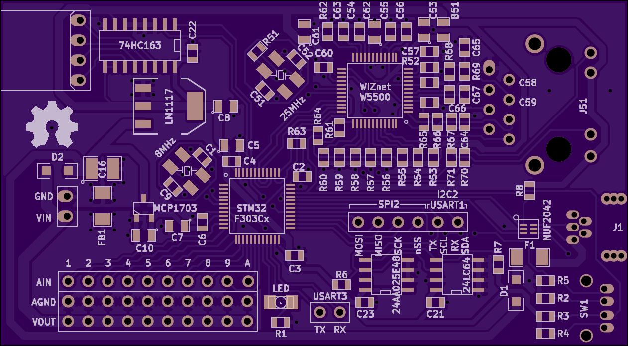
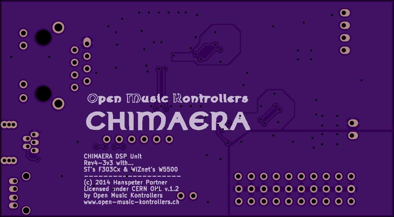
Here the renders from OSH Park:
![]()
![]()
Here the equipped board:
![]()
STM32F303Cx and libmaple F3 port
http://www.st.com/web/en/catalog/mmc/FM141/SC1169/SS1576/LN1531
The firmware is developed atop of LeafLabs libmaple.
http://leaflabs.com/docs/libmaple.html
We have ported 'libmaple' to the F3 line of STM32 chips already last year.
https://github.com/ventosus/libmaple/tree/F3
WIZnet W5500
People most probably have come across one of the hardwired UDP/TCP/IPv4 chips from WIZnet, as earlier versions (W5100, W5200) are found on most Ethernet shields for the Arduino and its clones. We use the newest version in the series: the W5500. Compared to its predecessor, the W5200, it gets much less hot and is more DIY friendly, as it comes in a 48-LQFP package instead of a 48-VQFN. It's an easy way to add networking to any MCU project.
http://wizwiki.net/wiki/doku.php?id=products:w5500:start
The chip can be configured with up to 8 individual sockets. In our case the sockets are configured as follows:
Socket Protocol(s) Port Description 0 MACRAW/UDP 68 IPv4LL (Zeroconf), DHCP client 1 UDP 123 Simple Network Time Protocol (SNTP) 2 UDP 319 Precision Time Protocol (PTPv2 event port) 3 UDP 320 Precision Time Protocol (PTPv2 general port) 4 UDP/TCP 3333 Open Sound Control (OSC) event stream output 5 UDP/TCP 4444 Open Sound Control (OSC) configuration in/out 6 UDP/TCP 5555 Open Sound Control (OSC) debug output 7 UDP 5353 mDNS and DNS-SD (Zeroconf) Time synchronization
For an expressive play we need highly resolved data. The higher resolved the data, the higher will be jitter, too. OSC has the advantage, that messages can be timestamped. We use this feature to get rid of network jitter. But in order for timestamping to work, clocks of MCU and host must be synchronized in some way. For this we use the precision time protocol PTPv2 for which there are free implementations for Linux at least. For the other OSs, one can fall back to SNTP, or do without time synchronization altogether.
https://en.wikipedia.org/wiki/Precision_Time_Protocol
http://tools.ietf.org/html/rfc2030
IP
The IP can be configured 1) statically, 2) via IPv4LL or 3) via DHCP. Using the device is thus plug'n'play. A minimal implementation of the Zeroconf stack with IPv4LL, mDNS and DNS-SD makes device discovery by the host straight forward, too.
OSC via UDP/TCP
The device sends its highly resolved continuous event stream via Open Sound Control (OSC) on a dedicated port, either via UDP or TCP.
http://opensoundcontrol.org/spec-1_0
UDP can be a bit faster and may be used on a simple network topology where packets are not likely to be dropped, e.g. direct connection device-host. TCP is to be preferred when packets are likely to be lost (e.g. complex network topology, wireless bridges, www, ...).
The exact OSC serialization format for the event stream will be featured in an upcoming blog post.
Configuration in/out and debug output also is (de)serialized to/from OSC via UDP/TCP on dedicated sockets.
-
Hall Effect Sensor (aka Expressive Button Continuous Distance Sensor) Breakout Board
08/03/2014 at 09:18 • 0 commentsWe will use linear hall effect sensor from Allegro, specifically, the A1304:
The sensor is fed with Vin=3.3V and outputs quiescent voltage Vq=Vin/2=1.65V when no magnetic field B is present. If we approach with a north polarized magnetic field (B>0), the sensor output voltage Vs will rise towards Vin. If we approach the sensor with a south polarized magnetic field (B<0), the output voltage will decrease towards 0V. The increase and decrease in voltage is linearly dependent on magnetic field strength B and the sensors sensitiviy S. The sensitivity for the A1304 is given by 4mV/G. 1G corresponds to 0.1mT. With an increase of the magnetic field strength (approach of magnet) of 0.1mT thus, the output voltage will rise in 4mV.
![]()
In our design, the magnets polarization will be fixed to either north or south facing. We therefore are only interested in one of the polarity ranges. To have a good resolution of the output signal for sampling by the ADC, we thus want to remap the bipolar analog output to a unipolar one. For this we use a simple OpAmp circuitry with an adjustable voltage reference Vr (0-3.3V) and gain A (1-10x).
![]()
When Vr is set at 1.65V, both north and south polarized signals would be amplified equally. If the reference is risen towards Vin and amplification doubled (A=2), the origianl north polarized signal range 1.65-3.3V will be mapped to 0-3.3V (Vq now at 0V). If the reference is lowered towards 0V and amplification doubled(A=2), the original south polarized signal range 0-1.65V will be mapped to 0-3.3V (Vq now at 3.3V).
Making the amplification adjustable from 1-10x, we can easily increase the sensitivity of the linear hall effect sensor from 4-40mV/G. This simple circuitry will allow us to experiment with different magnets and expressive button stroke depths to find the ideal combination of signal amplification (A), stroke depth and magnet dimension.
The final output voltage thus will be linear to magnetic field strength. As the magnetic field strength of a permanent magnet does not change linearly with distance, we will need to remap this signal to a linear one in the firmware.
The sources can be found at: https://github.com/OpenMusicKontrollers/space_whistle_button
Here the schematic from KiCAD:
![]()
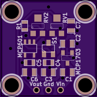
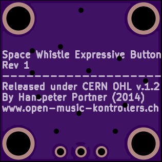
Here the renders from OSHPark:
![]()
![]()
-
Expressive Button (aka Electronic Valve) Design Considerations
08/02/2014 at 11:27 • 0 commentsHere now some design considerations what our expressive button should be capable of and how we plan to build it.:
Under an expressive button we understand a push button with a continuous analog output, e.g. the more you press it, the higher the analog output. Ideally, the relationship between pressure depth and output signal would be linear.
In the end, the expressive button may look and work similar to a trumpet valve. As we want to have an expressive control on produced music, the button must be able to be actuated really smooth and must not get stuck and should have low resistance in general. We thus will use a linear ball bearing and a matching cylindrical rod as a kind of smooth transitioning piston design. The rod will be loaded by a compression spring between linear bearing and rod head (not shown). The linear bearing will be centered above the piston hole in the top case sheet with a bracket. Inside the case, at the end of the rod, a strong Neodymium magnet will be mounted.
Our initial design will have an stroke depth of the button of 15mm. This is kind of a compromise trying to optimize expressiveness and speed of play. The deeper the action height, the finer we can control expressiveness, but at the same time, it becomes more tedious and needs more time to reach a given depth. De design allows to use arbitrary stroke depths by choosing cylindrical rod (and spring) height accordingly.
The magnetic field strength of the Neodymium magnet will be measured by the linear hall effect sensor. The nearer the magnet to the sensor, the higher the analog output of the latter. We thus will use the analog output of the hall effect sensor as a proxy for magnet distance aka button stroke depth.
There is a problem that will come up because the distance - magnetic field strength relationship is far from linear, it is more a cubic relationship. We may just use the output as-is or we may want to remap it to a linear scale. This will depend a lot on what we want to steer with the derived control signal in the end. It may be best if it can be changed on-the-fly in the final firmware. We will elaborate more on this problem in an upcoming log post about the underlying math done in the firmware.
Most linear hall effect sensors with analog outputs do measure both north and south polarized magnetig field strength. We however are only interested in either north or south polarized magnetic fields, but not in both. We therefore will need to remap the analog output signal to span the whole voltage range sampleable by our ADC, but this will make part of an upcoming log entry about the accompanying linear hall effect sensor breakout board.
![]()
-
Pressure Sensor Breakout Board
07/29/2014 at 18:03 • 0 commentsWe have designed a simple break out board for the MP3V5010DP pressure sensor which comes with its own low drop out voltage regulator (MCP1703) so you can power it with e.g. 5V instead of the needed 3.3V. Additionally there is an OpAmp (MCP601) on board to add some arbitrary offset (0-3.3V) and gain(1-2x) to the sensors analog output via two trim potentiometers. All the components are SMD, which makes the board dimensions rather small (20x40mm), ideal to fit into nice casing.
The sources can be found at: https://github.com/OpenMusicKontrollers/space_whistle_pressure
Here the schematic from KiCAD:
![]()
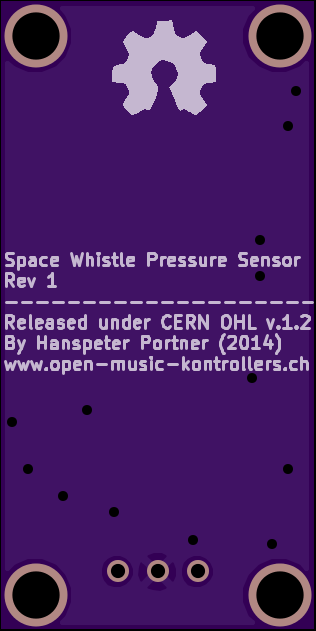
Here the renders from OSHPark:
![]()
![]()
-
Choose a pressure sensor (or how much respiratory pressure can the human lung create?)
07/27/2014 at 17:50 • 0 commentsWe need a a means to measure respiratory pressure for our wind controller. So which one should we choose? What are our prerequisites? Are there different kins of sensors out there?
To mimick a wind instrument best, we would have to go with a flow sensor, but we opt for a simple pressure sensor instead, because they are cheaper.
https://en.wikipedia.org/wiki/Flow_sensor
https://en.wikipedia.org/wiki/Pressure_sensor
Using a simple pressure sensor may get tedious to operate though, as the air cannot escape which is kind of unnatural for a wind instrument. But we can easily come by this by introducing a so called bleed to the system. The bleed is nothing else than a small escape route (aka hole) in the system for the air. Ideally the bleed can be made dynamically adjustable by means of a valve.
We need it to operate at 3.3V and we would like to get an analog signal back from 0-3.3V, too over the range of pressures a human can produce.
So what is this human pressure range? The answer can readily be found in a paper:
http://www.ncbi.nlm.nih.gov/pmc/articles/PMC459855/
As we will use a bleed for a more agreeable play we take a conservative value for women out of the article which is a maximal respiratory pressure when exhaling of 100cmH20. Height water column is not that common a unit these days, though, so we need to convert it to proper SI units and possibly to the imperial &@%#, too, which gives as 9.8kPa or 1.42 PSI.
As we are mainly interested in relative pressure (relative to ambient), we need a differentail pressure sensor rather than an absolute one (relative to a vacuum). With an absolute one, we would also have the possibility to suck on the sensor, but the quiescent output would vary depending on ambient pressure (e.g. height above sea and influenced by weather), which we would rather not have to deal with.
Responde time should be at least around 1ms, a prerequisite for an expressive play.
Those are our prerequisites, now we fill them in to DigiKey and out we get a differantial pressure sensor for up to 10kPa (1.45 PSI) @3.3V, the MP3V5010DP from FREESCALE for around 8.5€.
![]()
The MP3V5010 series piezoresistive transducers are state-of-the-art monolithic silicon pressure sensors designed for a wide range of applications, but particularly those employing a microcontroller or microprocessor with A/D inputs. This transducer combines advanced micromachining techniques, thin-film metallization, and bipolar processing to provide an accurate, high level analog output signal that is proportional to the applied pressure.
The datasheet tells us that the sensor will output an analog signal linear to pressure from 0.1-3.1V when operated at 3.3V. We may thus want to scale this to the full 0-3.3V range for full resolution sampling by the ADC with some simple OpAmp circuitry.
Next step will be to design a breakout board for the MP3V5010DP and test it. Although the MP3V5010DP is a surface mount part, it is big and comes with huge J-wings and only 3 of the 8 legs need to be connected. It should be easy even for breadboarding if you should be in a hurry.
Our next step will be to design a breakout board for this sensor to make it easily embeddable into any wind controller project (we have got more ideas than this one only, ....)
Note to us: The datasheet says that the sensor was designed for dry air and may be adversely affected by moist air, we need to address that somehow by separating the really wet air (from the lungs) and the dry air acting upon the sensor. E.g. we may want to put some hydrophobic liquid (aka oil) in between two separate air columns to hinder moisture to reach the sensor...
Space Whistle - wind controller - musical IoT
A highly responsive wind controller with expressive continuous push buttons based on linear hall-effect sensors - A musical IoT device -