 Metalnat
-
The Second Half of the ControlOrSense Project...
10/27/2017 at 07:59 • 0 commentsVideos!!!!!
Well, not just videos. This whole project was started as a way to make electronics accessible to others. When i would teach classes and cover all the things it would take to "develop a simple game" students would almost always feel overwhelmed. So this is a big leap into trying something new and always available to anyone looking for it. With the help of my college friend Roger we have now put up several recordings, publicly available as a electronics primer. This will lead into the larger builds and the madness of how I see the world.
For example: a button as understood by anyone passing by might be an encased plastic contact that happens to make a clicking sound when pressed. unknown to them they are engaging into the management of conductive surfaces. And that's where we engage the viewer and promote a curiosity about what around them can be made into an improvised button.. It's this key component that will feed into the creative part of what ControlOrSense was inspired by at the beginning. Let the fun begin!!!!Now I know I'll make mistakes and I do my best to only convey info learned from experimenting, but if I don't share, then am I really pulling my weight? I think not. We learn from failing and through just crazy obsessive drive we get past the unknown. We grow and learn. This is what I want the world to be. So do feel free to pitch in and be part of this chaos.
~Metal
-
Update Post Residency
10/14/2017 at 10:30 • 0 commentsThe last day of the residency I got V1.0 to work as a native joystick on the computer. I tested it with two different game demos in Unity, one for racing and the other as the Tank demo. Both were different sockets for the Control-Or-Sense board and worked exactly as expected.
The curious things to note are the fact that i had to deviate from the Teensy schematic and remove the resistors in line with the usb data +/- pins. to get it to connect and flash. And on the phone it's not understood as a joystick. making part of my build a bit difficult to test. Could very easily be due to the usb pin deviation. Also I now have a several things to change from V1 to V2 based on seeing this in action, and having gained some new experience since the residency. Also some people said while testing that the connectors are a bit tough to take in and out. I'll be using the other connectors on my next dock board while still looking into others as well.
![]()
Not being entirely happy with the through hole components other than being quick to build on the board and source locally, I have devoted a month to practicing smd soldering and just this last week i had an amazon delivery of solder paste and an electric skillet... some of you might know where i'm going with this, but for anyone not sure yet, follow this link. But the quick and dirty is i found a link on hackaday for re-flowing boards using a skillet. It was really easy actually but definitely an observant task. And even though I have not yet ordered any solder mask for this, with a pipette attached to the solder paste tube, and some tweezers i was able to prep, place, and bake functioning boards for another project. 4 fully functional boards for a client project actually.
![]()
What this means for me is that i can now with confidence do a full overhaul of the board. With the KiCad practice as well I'm quite excited to dive into v2.
The other big update is that I now have the lighting, microphones, and daily help filming for the education videos that have always been the background goal of this as well. Currently 1 week of filming has yielded short videos of Resistors, Basic Leds, Mission Statement, and a couple others. Next to record are Buttons, Potentiometers, and Addressable Leds. I'm now being shown tips in Final Cut Pro as well as Premiere Pro while I record B-roll for the Resistor and Led Basics videos. So expect those videos within the next week!
-
Living on the Edge.... connector
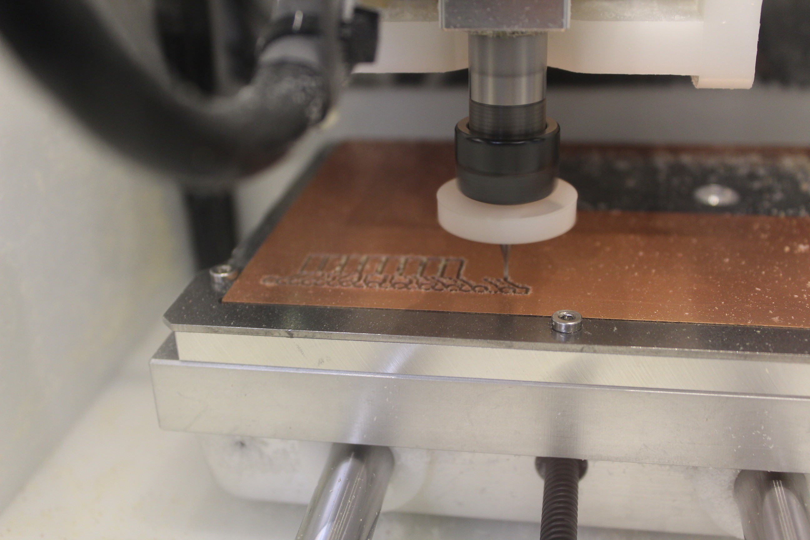
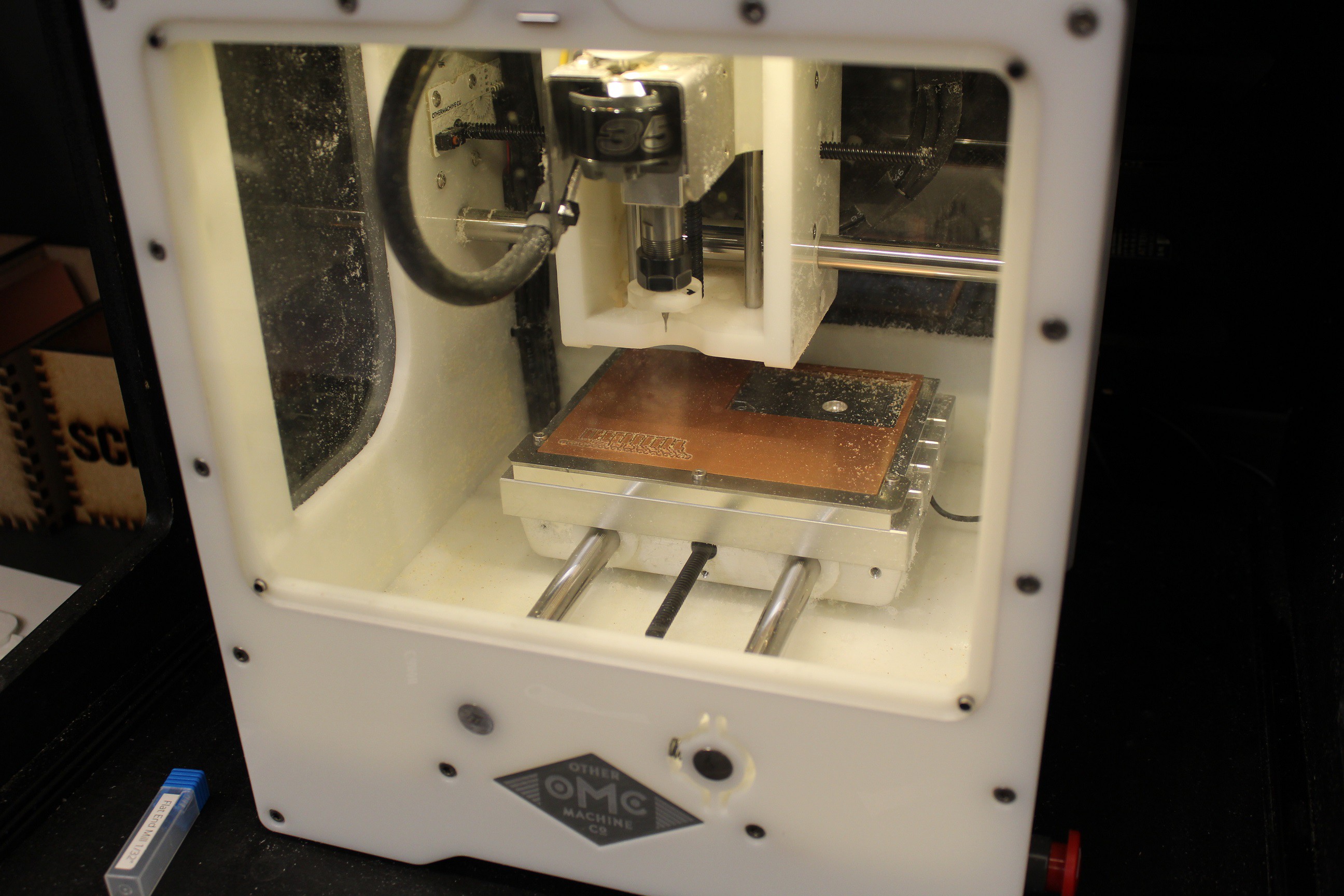
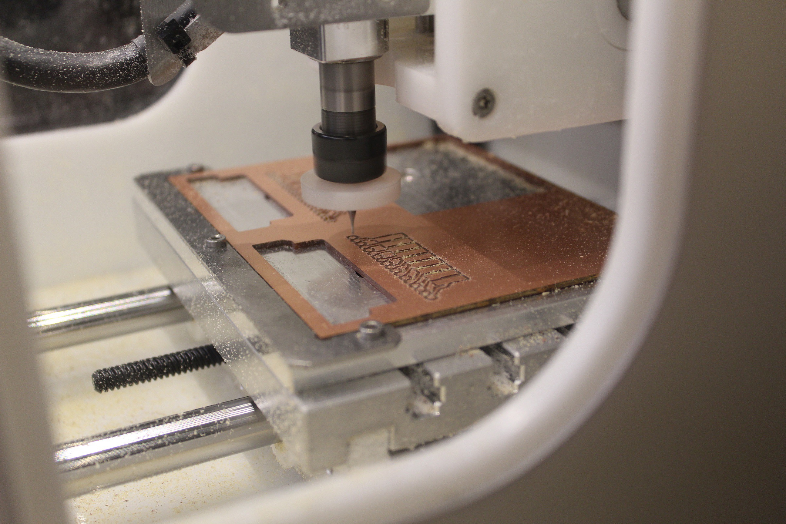
05/19/2017 at 21:59 • 2 commentsSo one of the features I absolutely have to have is what's called a card edge connector. Inspired heavily by the Nintendo cartridges of old. My first system was Atari with the only game of ET.... so we don't count that. Either way it's a feature I really wanted for... reasons. Now after having several default footprints in KiCad be anything but friendly when i go to fit check everything I decided to skip looking hard for anything that might work and instead get my calipers and just do some observation work. Then I had a fun time juggling top and bottom layers while placing pads. Then off to the OtherMill!
![]()
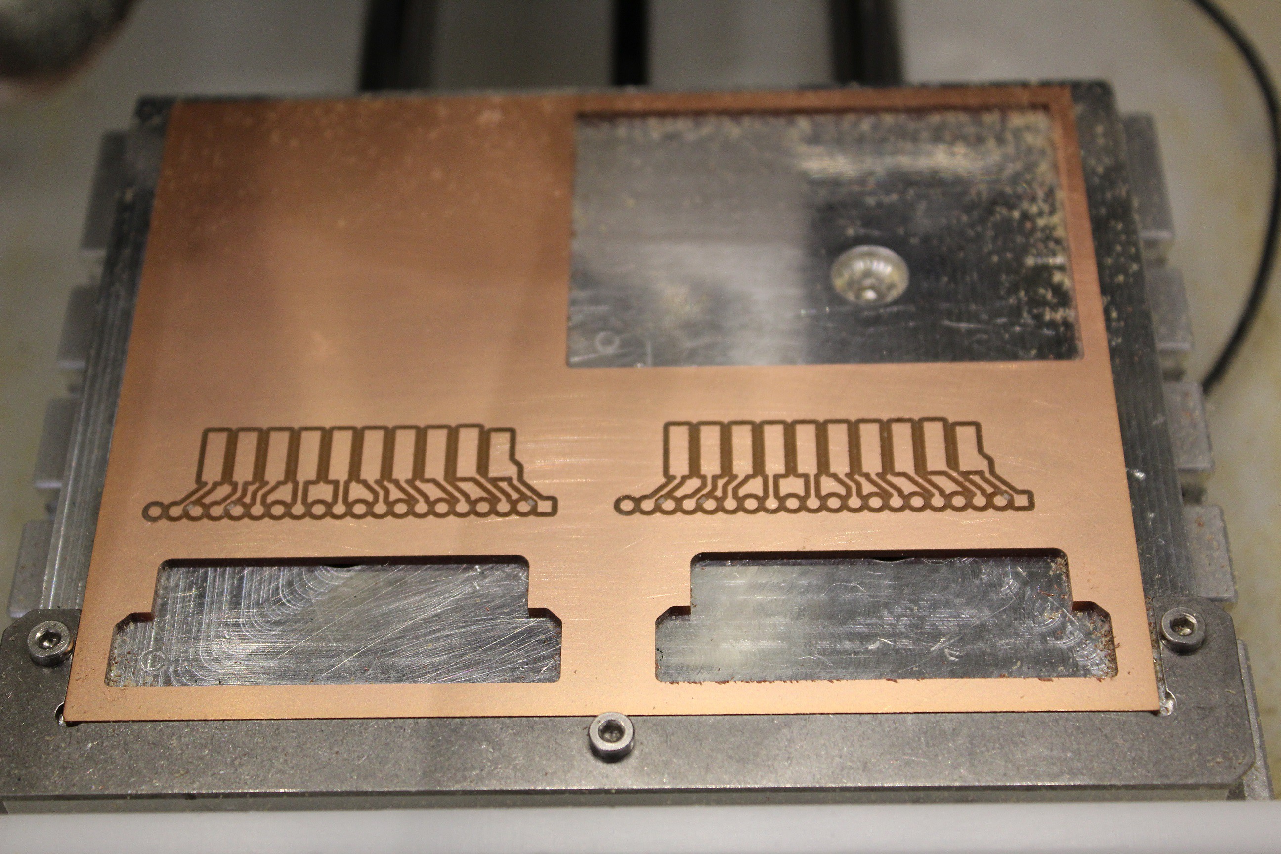
Starting to look like the breadboard friendly test piece.
![]()
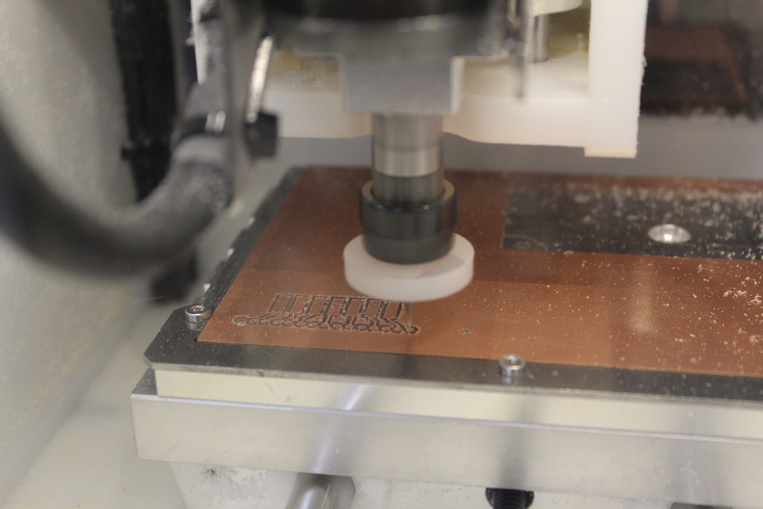
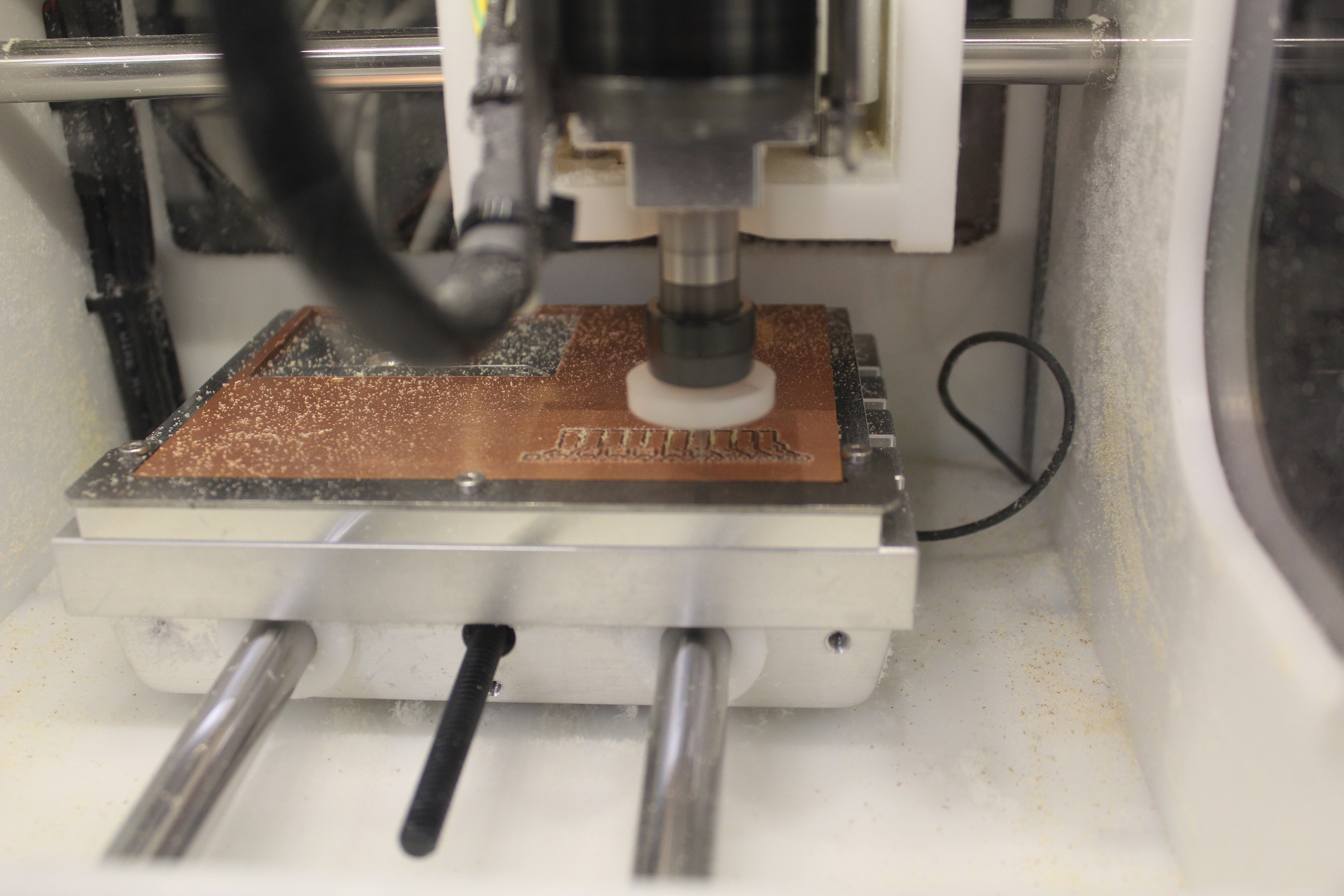
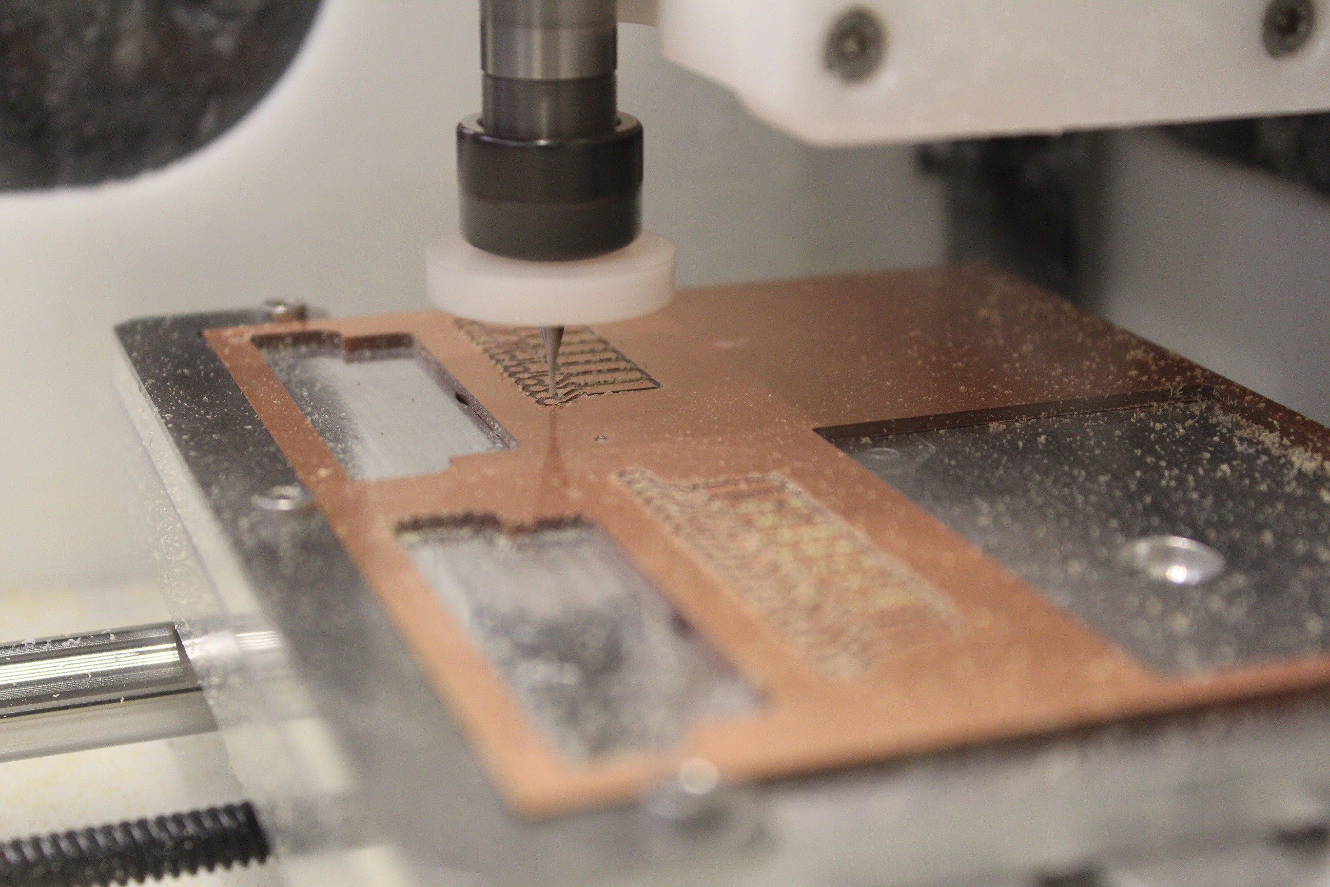
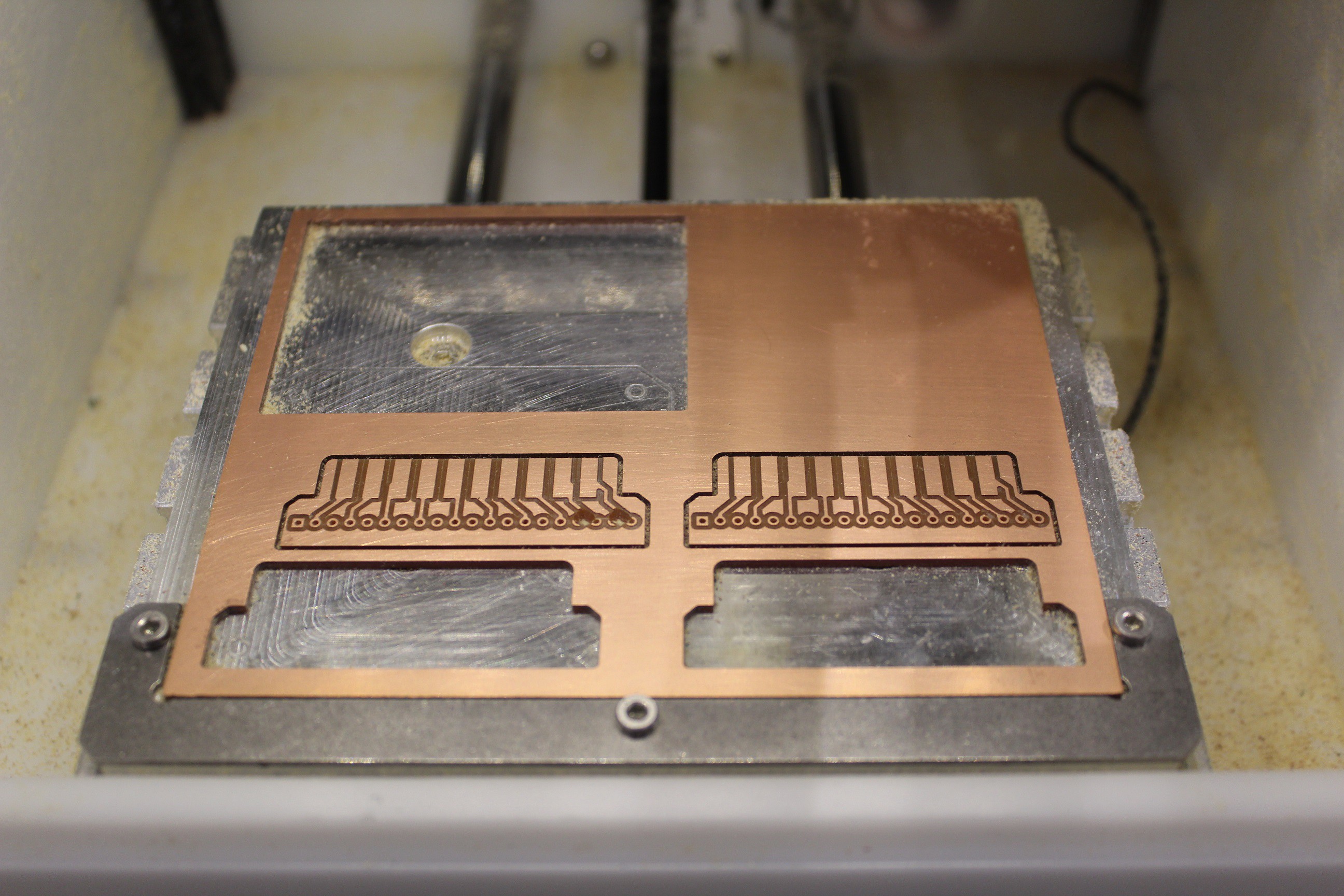
Side one is done, now to flip and cut side two.
![]()
And on to side two. The cool thing in the Othermill software is just a toggle switch in the UI fro front/back. Also there are toggles for Traces, Holes, and Edgecuts. This is important to note because cutting out edges from board on first cut will cause for many a bad time.
![]()
And the first impression looks good.
![]()
Bring together parts I'll be mating.
![]() And success! I metered out continuity and everything tests out beautifully.
And success! I metered out continuity and everything tests out beautifully. ![]()
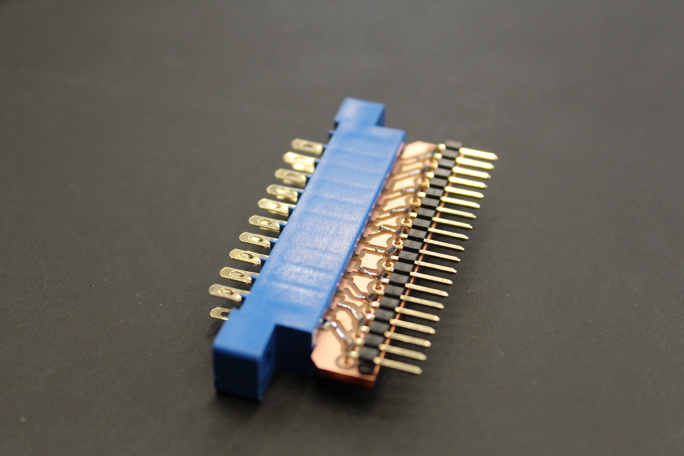
Just look at it!
![]()
Time to cut out more for testing.
![]()
This is a better shot of first side cut. Notice that i recessed one tab, that is the +5v so that i'm better ensuring GND is connected before applying power.
![]()
Time to cut second side.
![]()
And i made an oops. Two large holes on left side are do to the v bit not making contact on the flat part of the platform on homing. Seems homing position had been changed since I last used the machine, and has since been resolved, But I'm the guy to find out all the issues. Lucky me. :)
![]()
![]()
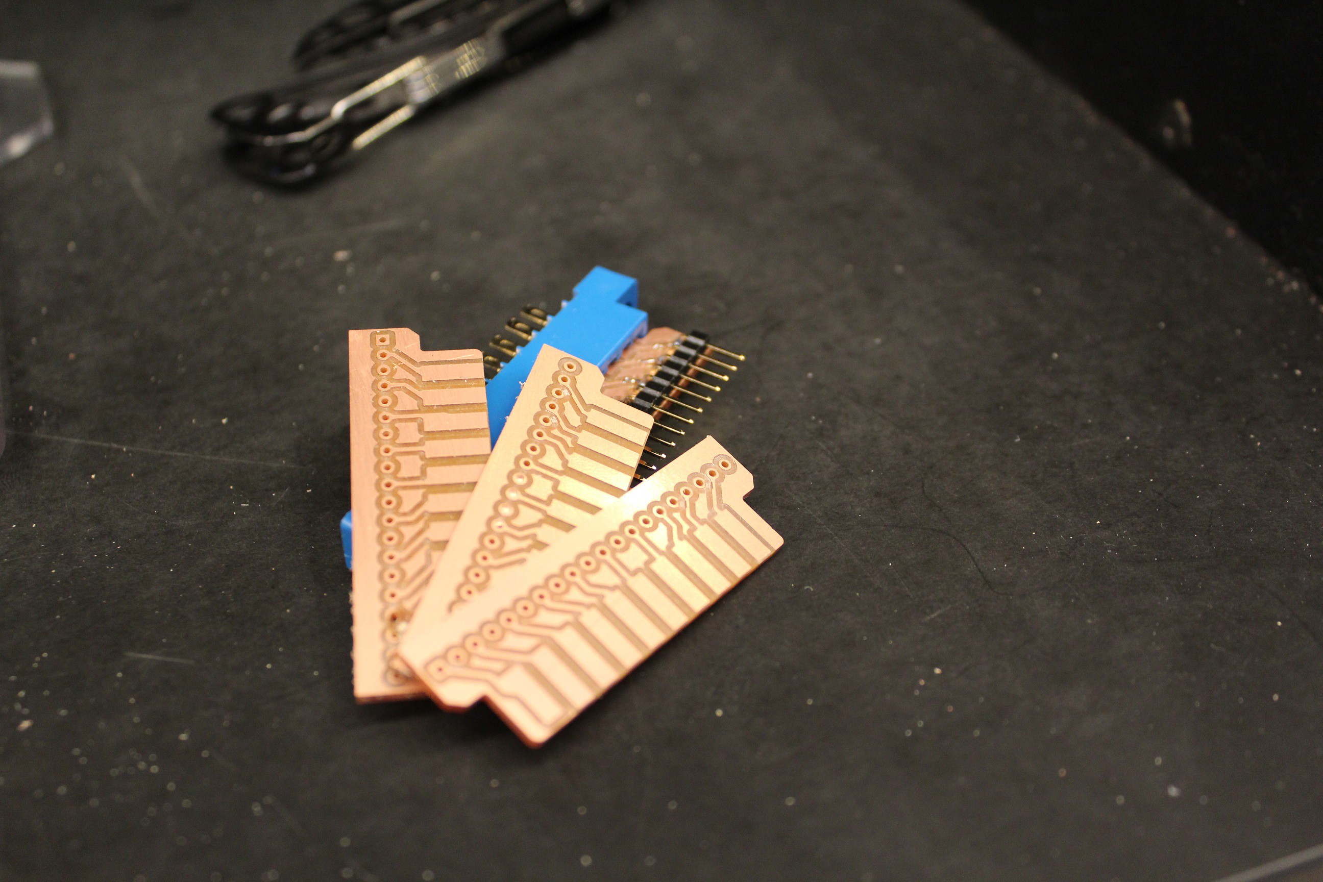
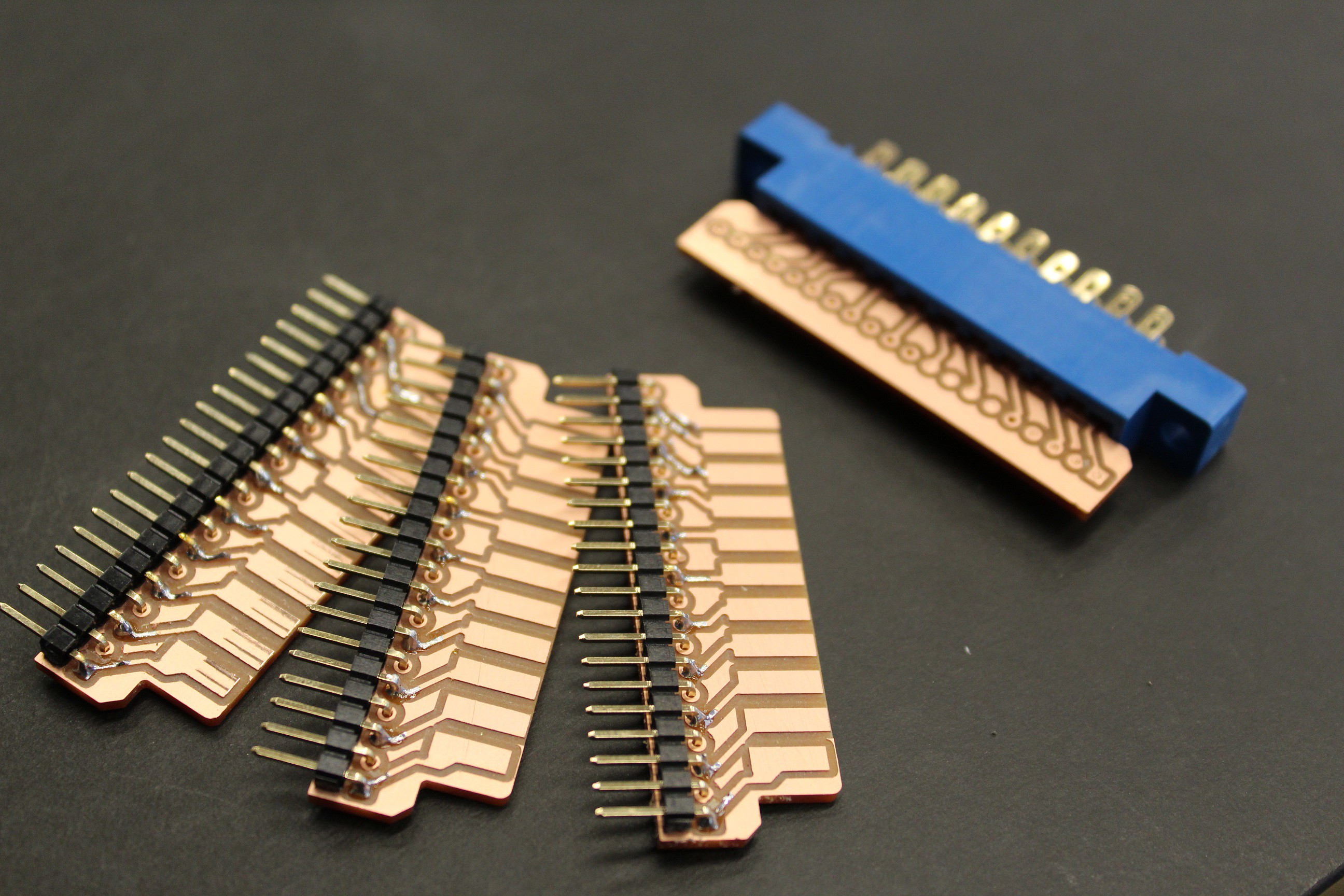
And here is a happy family of breadboard friendly edge connectors.
![]()
-
This is Why I Can't Have Nice Things... Sorta
05/04/2017 at 09:09 • 0 commentsI have always had the need to take things apart and see how they work... imagine the most curiously destructive 2 year old. That may be close to how i was and still am. Although now i know electricity can hurt, and one can accidentally weld multimeter probes to objects. And since a lot of this project is going to be not only replacing what we define as a button and actually educating people how to observe what already exists, it's about time I do a tear down with intent to educate.
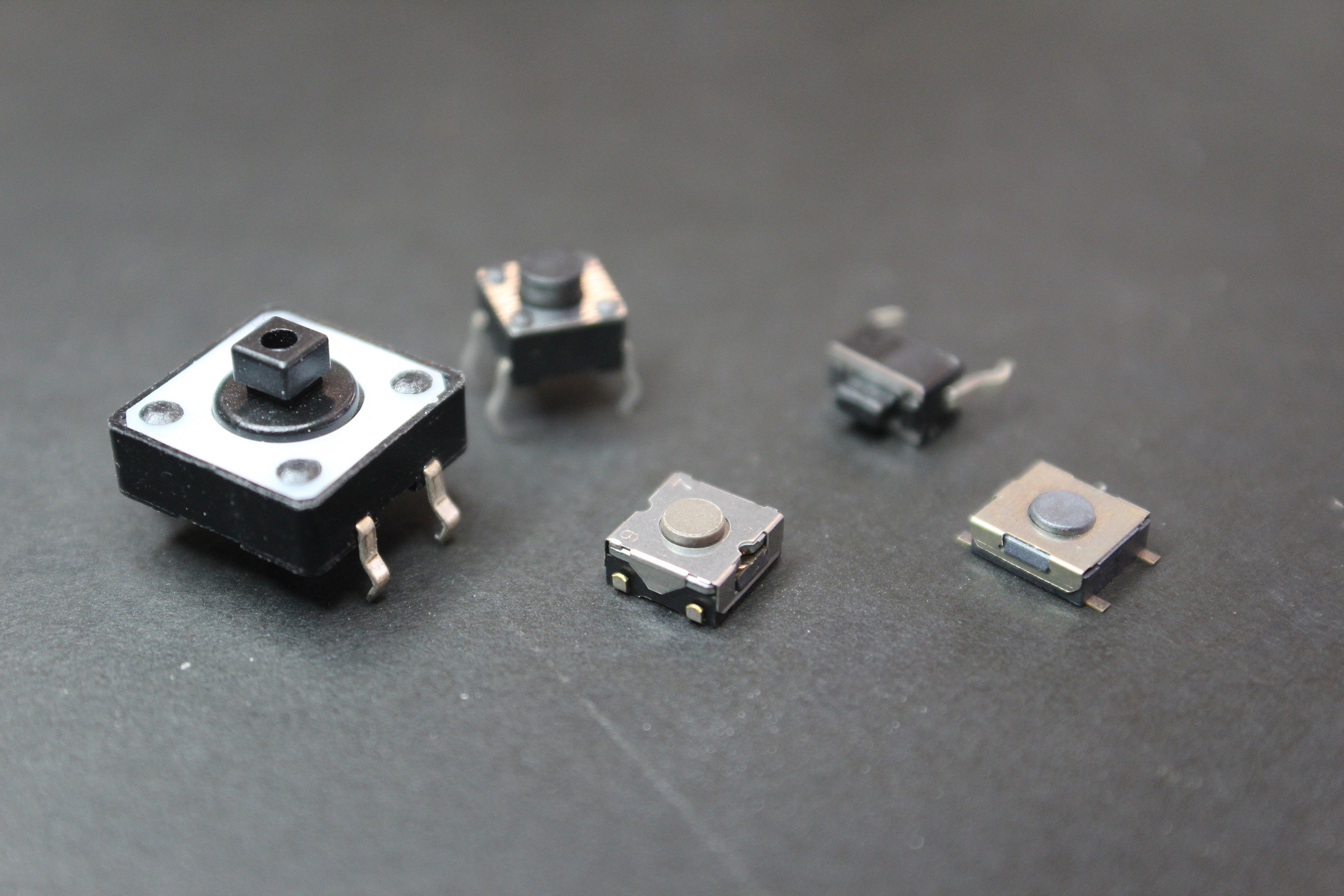
Below we see a few buttons. Different shapes, sizes, and mounting methods yet all of these have the same purpose. To momentarily compete a conductive path across the legs of the button when the top it pressed down. (i hate saying depressed... sounds silly even when talking about buttons). All of these buttons happen to be "Normally Open" which means that the legs are not all connected when no force is applied to the button. Thereby making an "open" circuit.
![]()
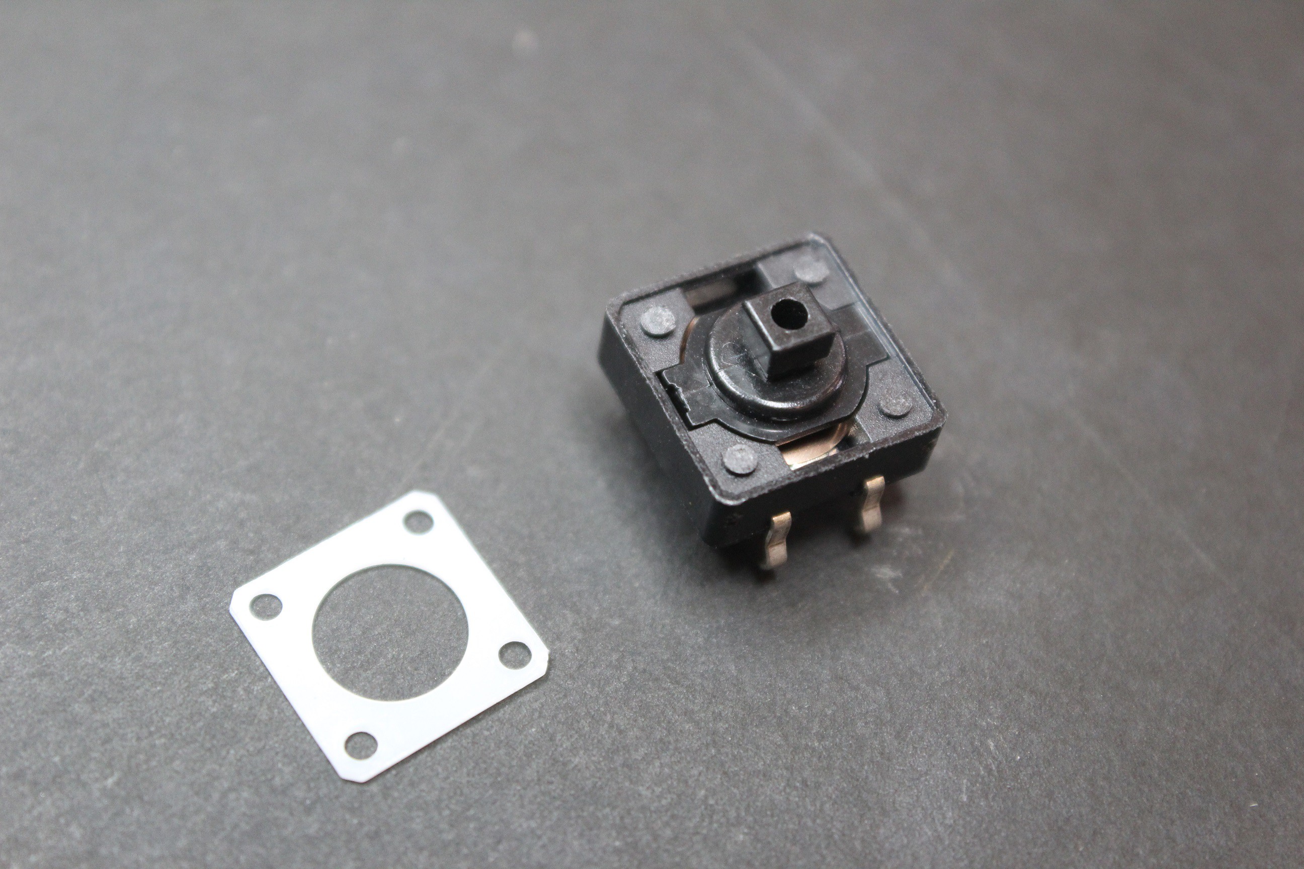
Now to see how this works mechanically we need to open one up and try to take note of nearly every detail. It's not super import to note everything as long as we note the important parts, like how connections are managed between pushed and not pushed, and maybe what pushes back to return to a open state when not pushed. After all those are the features of this particular component that define it's usefulness. First thing we do is cut the plastic rivet tabs on the top holding the white piece in place so that we can pull it up and off.
![]()
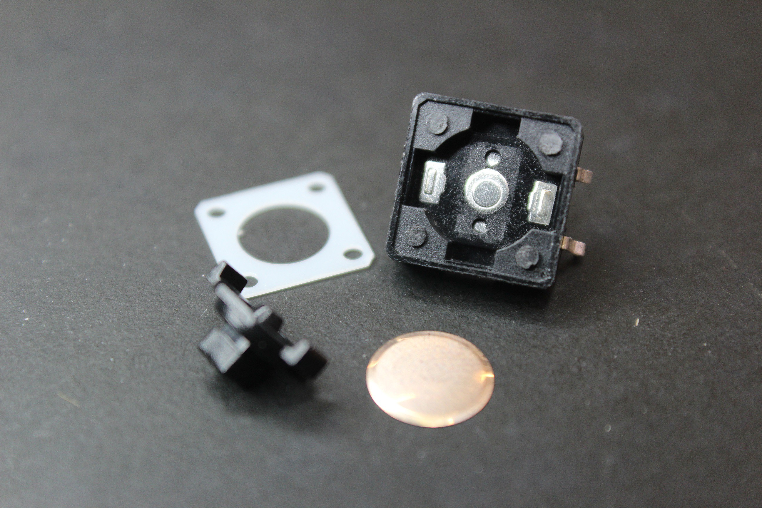
This then make it possible for us to simply pull the part of the push button that we make contact with out. Take note of the shape of this piece because it gives us info on how it distributes force when we press down on it. There is a center piece that extends right below where we press, as well as two legs on the sides of the button as well. The legs are slightly longer than the middle piece. Just an interesting observation at the moment.
After we pulled the button we also notice a round piece of metal. One immediate thing to note is the shape. it is not flat, it's dome shaped facing upward towards the plastic piece we just pulled. This means that at rest the dome piece of metal pushes upward on the button contact and when we press down we are in fact making the dome piece of metal invert. At least in the center. Since we can see a slight change in the dome's edge I would make the assumption that the edge itself might very well not invert, but only the center. Reason i say that: with all of the things I've taken apart, it's very rare that some detail has not reason or history for being there. This is no exception.
![]()
Now it gets to the fun part. I can either melt away the plastic in a potentially harmful out gassing process (curious how i'm still alive with all the experiments) or I can lean on another skill plus the use of a multimeter to do what is called continuity testing to find out where all conductive surfaces are, and then with the use of calipers and my favorite modeling tool Blender, model out observations. We'll save that for my next lengthy post.
See you then!
~Metal -
Reason # 1872 Why I Love This Community.
05/04/2017 at 09:07 • 0 commentsDiving into connectors was somewhat easier and more difficult than expected. But luckily I got some unexpected help on this front. See I knew that i wanted to explore the different JST (Japanese Solderless Terminal) connectors. I'm sure most of you have already had some interaction with at least 2 different types or "series" of jst connectors. Be it the LiPo battery connector, the power connectors for RC cars, or something like the Seedstudio Grove Kit. These things are everywhere! But without knowing the different series it could be most interesting ordering blindly online or just finding connectors based on number of contacts.
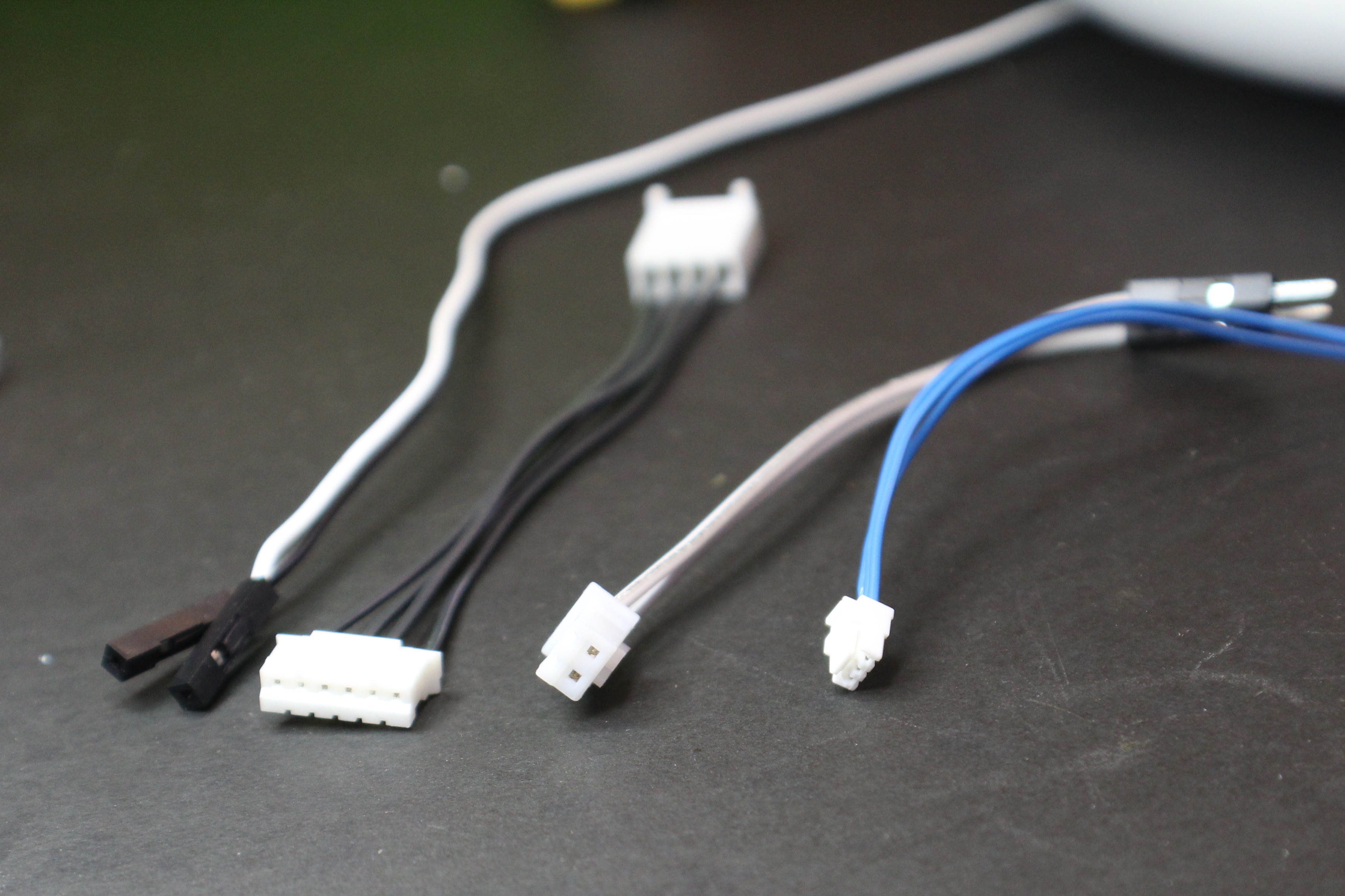
![]() Left to Right: header pin connectors, stepper motor cable, JST XH to header, and then JST GH (So tiny)
Left to Right: header pin connectors, stepper motor cable, JST XH to header, and then JST GH (So tiny)Lucky for my I happen to follow a fellow maker in instagram by the name of Neurotinker who at one point posted a really tiny GH series connector during one of their builds. I asked the series and that led into the offer of help crimping some cables. I put in the order and sent them the parts directly, where they put some cables together and even created a test rig! This community is amazing and I strongly recommend following them on instagram. The moment I knew i was among peers was the moment they posted this gem of a 0-Layer Teensy!!!! Seriously love that this exists.
For anyone curious about all the different series of connectors that exist Go Here.
~Metal
Control Or Sense
Supply Frame Residency project to make a no-code custom controller infrastructure for mobile devices and other game systems.


 And success! I metered out continuity and everything tests out beautifully.
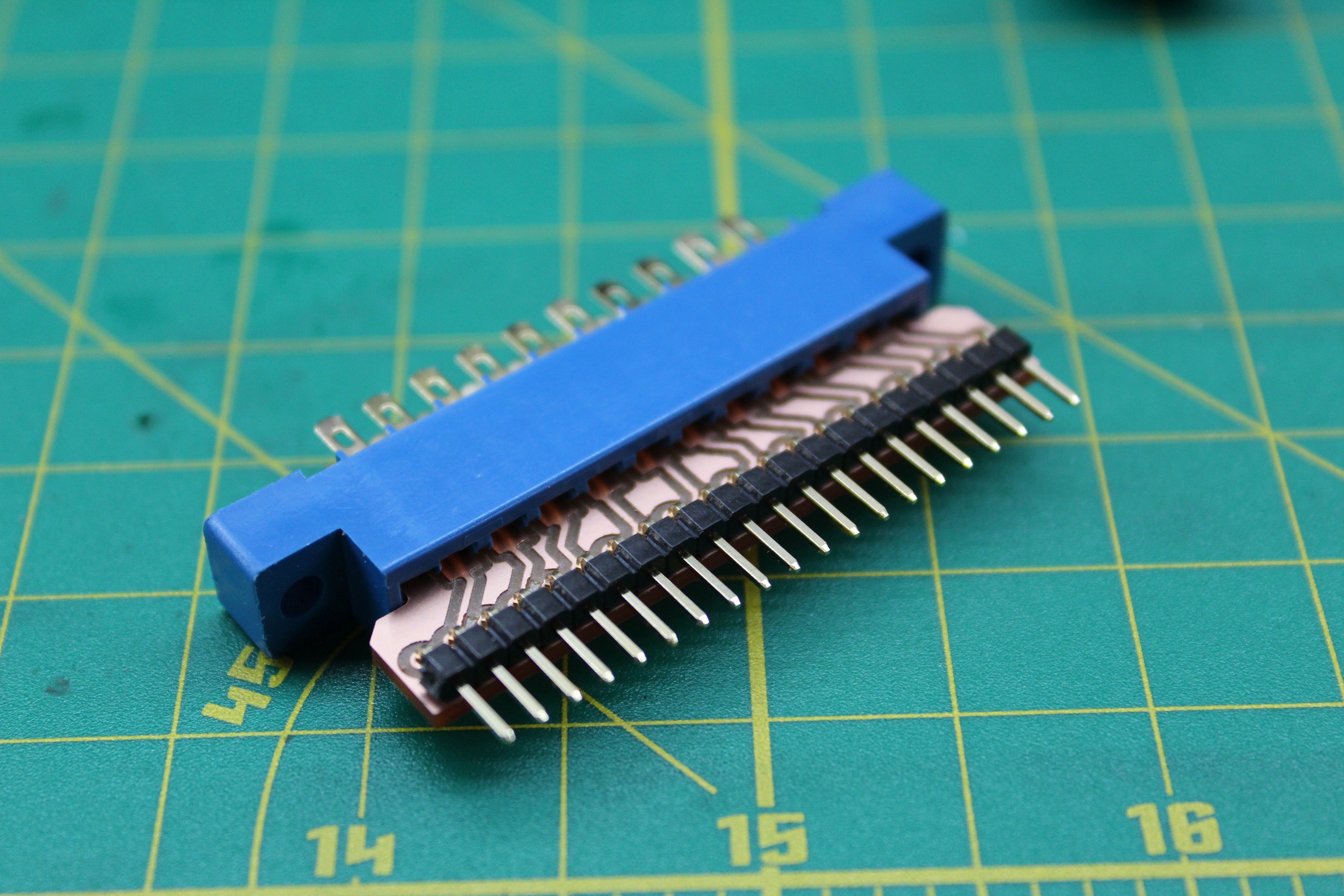
 Left to Right: header pin connectors, stepper motor cable, JST XH to header, and then JST GH (So tiny)