This last week has been spent getting more up to speed tools like the ShopBot and designing lamps that can be accomplished using tools available in the Design Lab. This next design prototype is called "archMetal1".
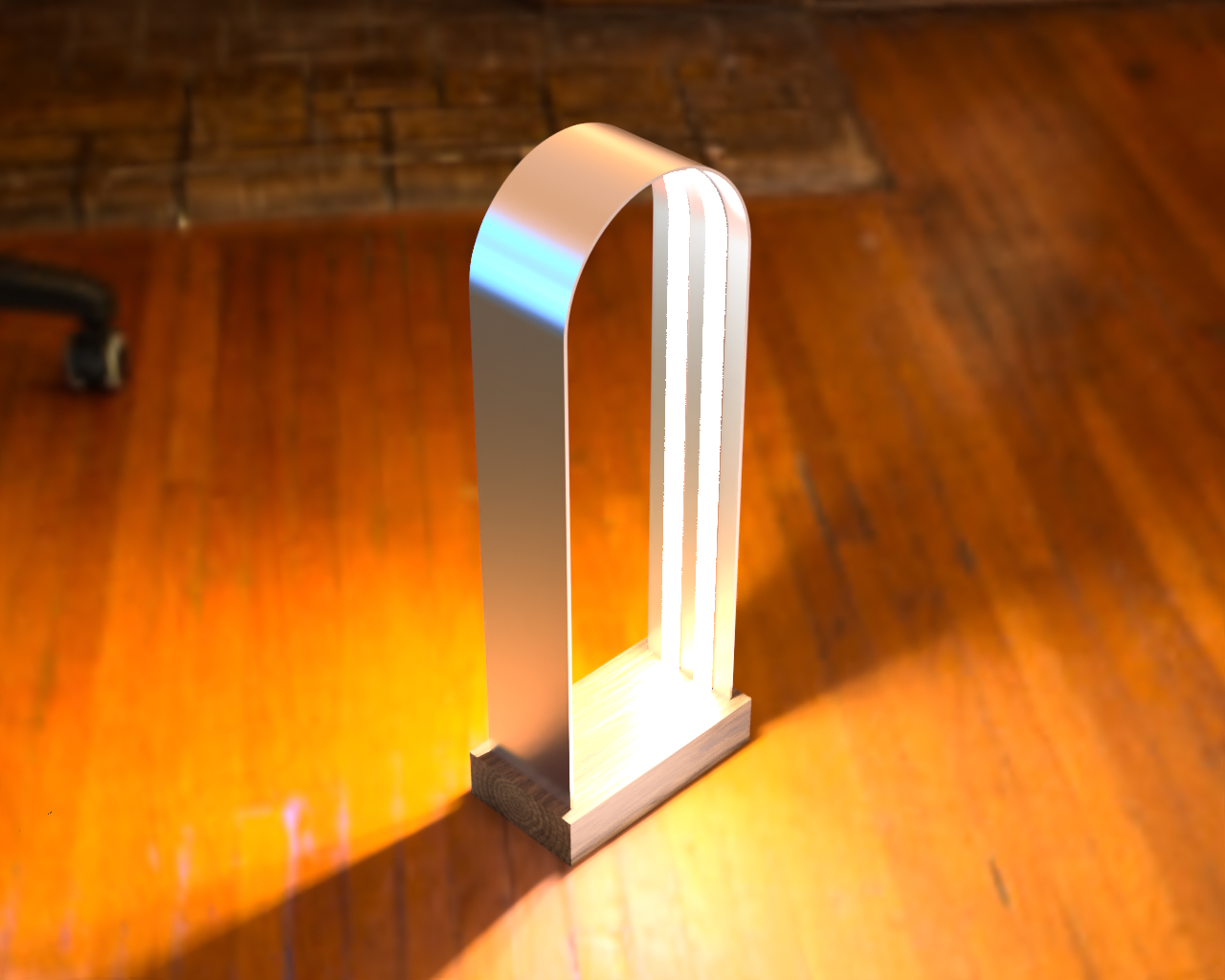
This design is a better platform than the first lamp for testing flexible but structured diffusion materials (plastic PP & PET sheets, maybe velum, but not cloth or plexiglass). The design consists of a main metal arch embedded in wood, with the LEDs attached on the inner side of the arch. The diffusion material attaches with standoffs from either the centerline or edges of the metal bar, like this:
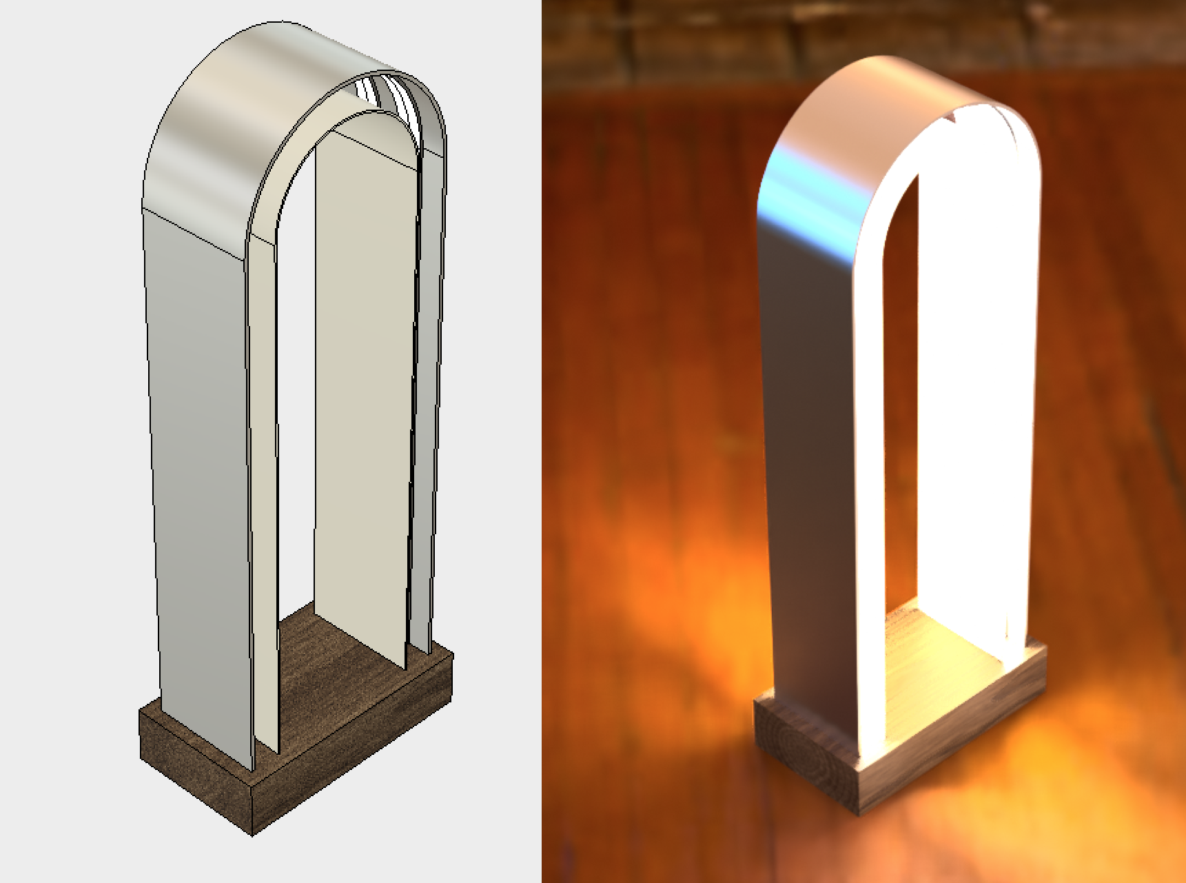
Can we prototype this up in a few days? The design specifies a 4"-wide bar of aluminum at 1/8" thick and 48" long, sunk into a 9"x5"x2" wood block. All I had was 2" x 1/8" x 48" aluminum bar. This should still be wide enough to demonstrate the design and for future diffusion experiments.
That width turned out for the best given that the Design Lab doesn't yet have the metalworking tools needed and I don't have full command of the ShopBot yet to make my own tools. I think this bender might work for me in the future. For this prototype, I faked up a few metal benders using scrap wood, based on what I've seen on Youtube, particularly this video:
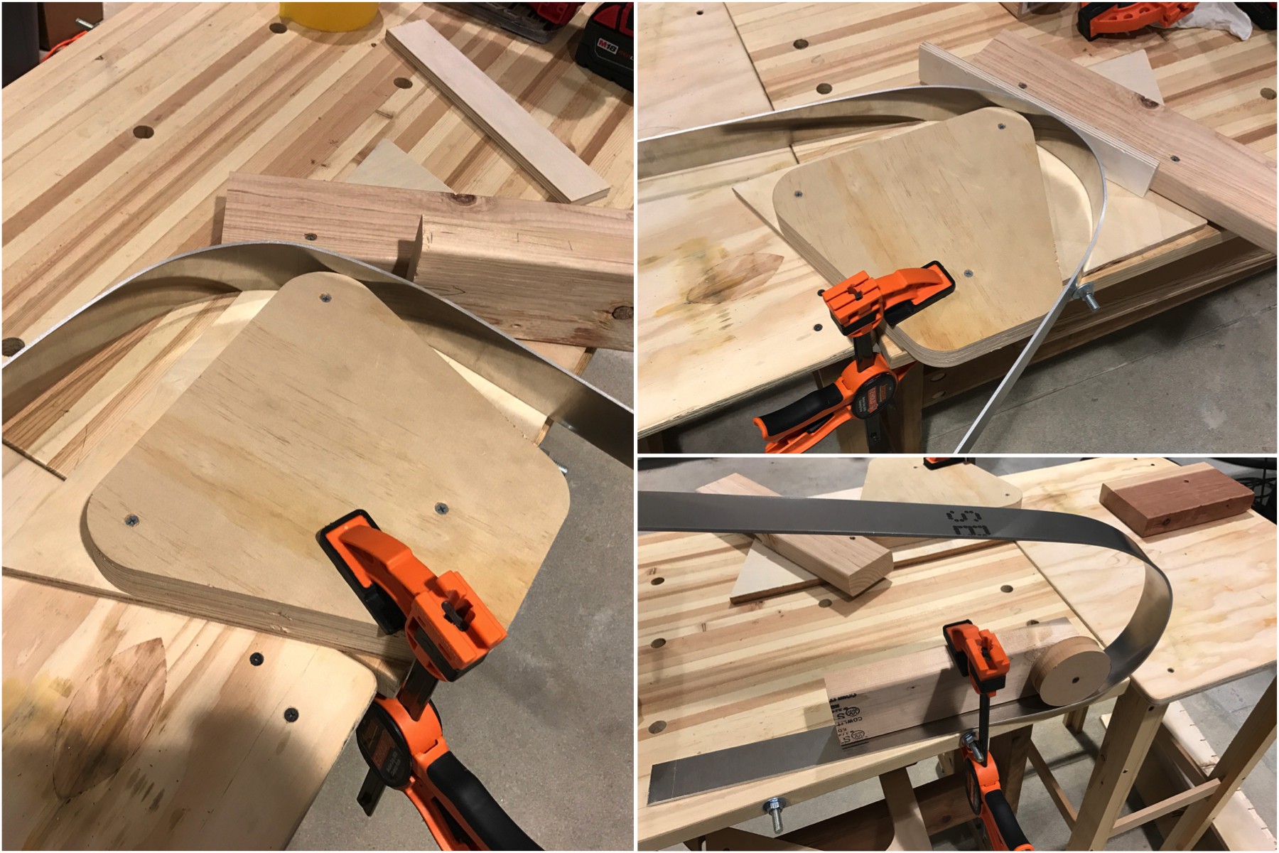
These benders worked up to 120º bends but I did end up manhandling it quite a bit to get it into the shape I wanted. And even then it's not very even due to the lack of precise tooling. Oh well, this is a prototype after all. After a small amount of sanding, the U-shaped bar was mounted to a block of solid wood.
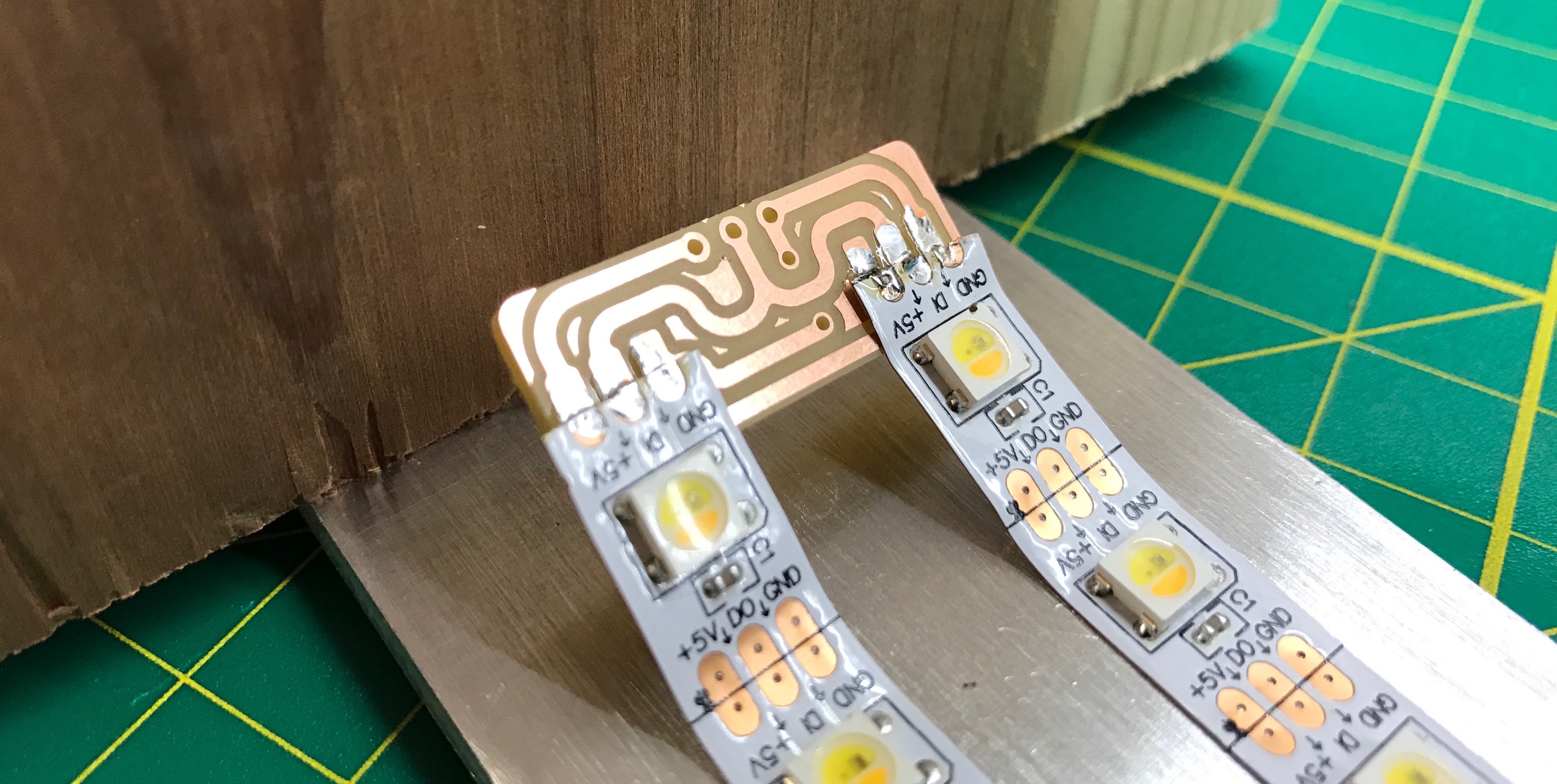
The next step was laying out the LEDs and wiring them up. The original design calls for four LED strips arranged as two pairs, with space in between and on the sides. With the smaller 2" bar I reduced the number of strips to two so I could have the spacing I wanted for diffusion standoffs. To help with wiring, I quickly made a special NeoJoint splitter in Eagle to accommodate the spacing. After a 2-minute milling on the Othermill I had it and It works great. And it looks pretty neat:
I also made an updated version of the rotary encoder test board. It's lower profile and features a separate DC power input for easier stand-alone operation. It also swaps top & bottom copper layer because on the Othermill, it's faster to mill top copper (saves a button press). In the image below, original test board is on top, the updated one is below it.
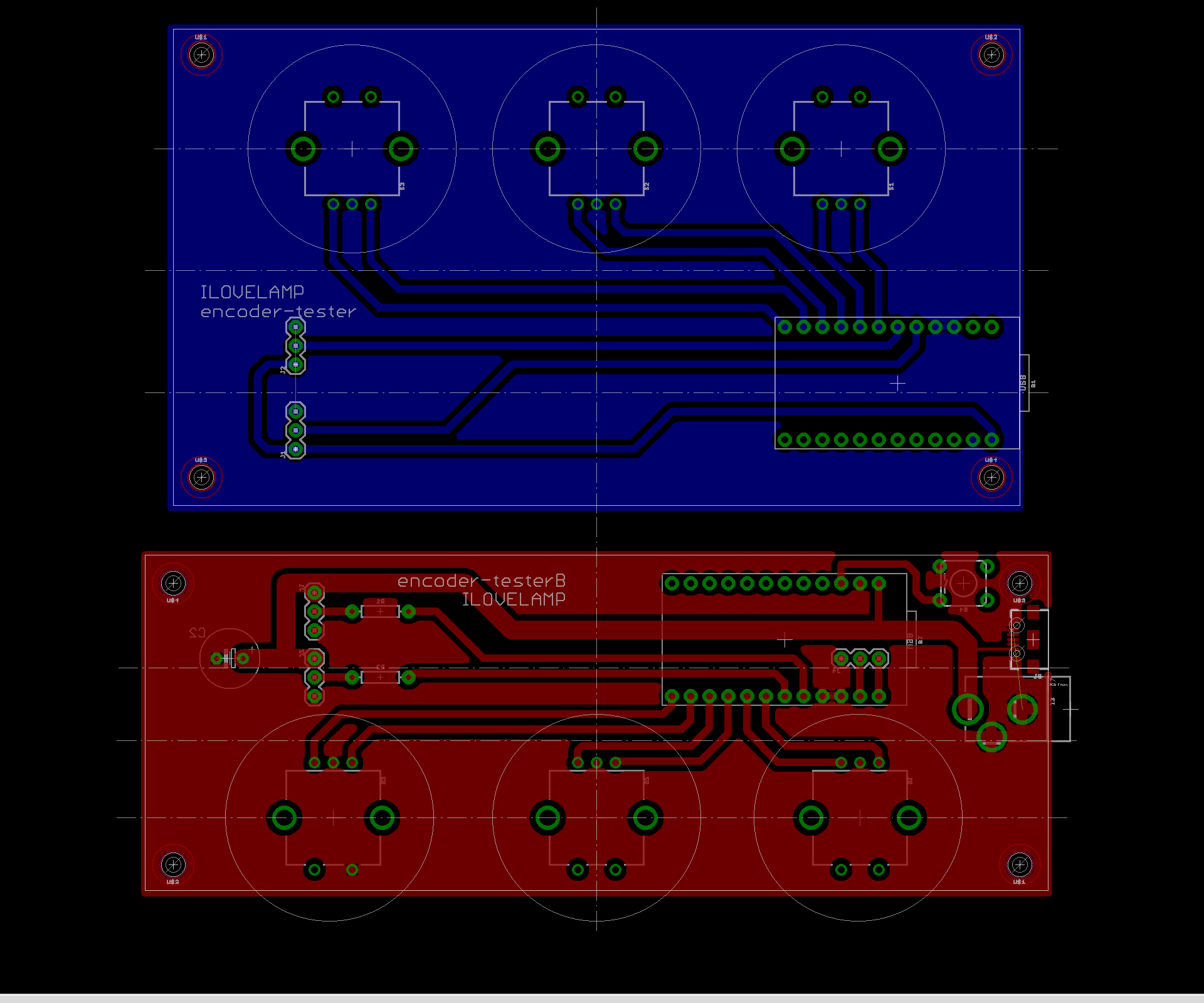
I milled up one of these on the Othermill, populated it, tested and mounted it.
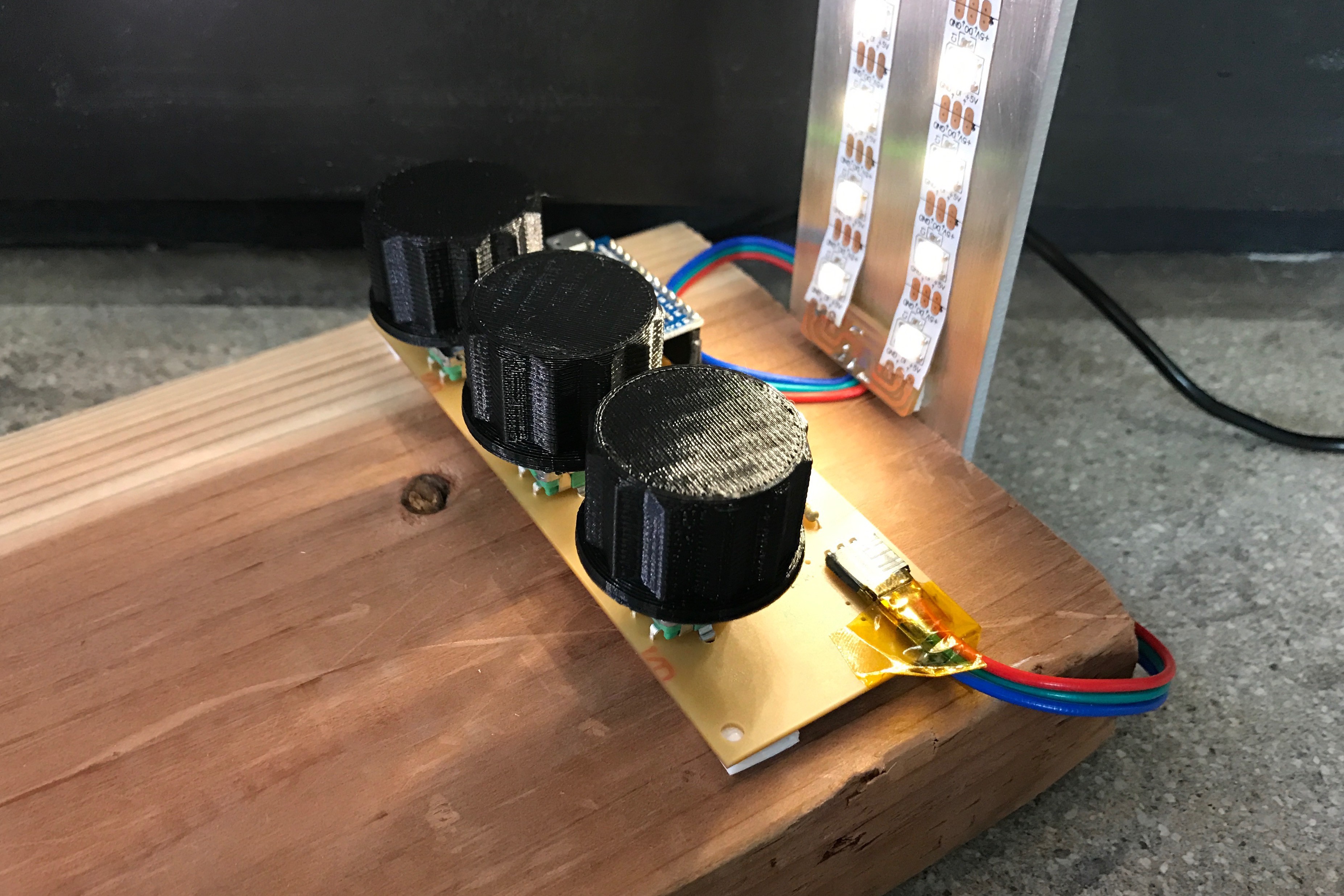
All that's left is to upload a test sketch to the Arduino Pro Micro that's driving the lamp and power it up. This is the result.
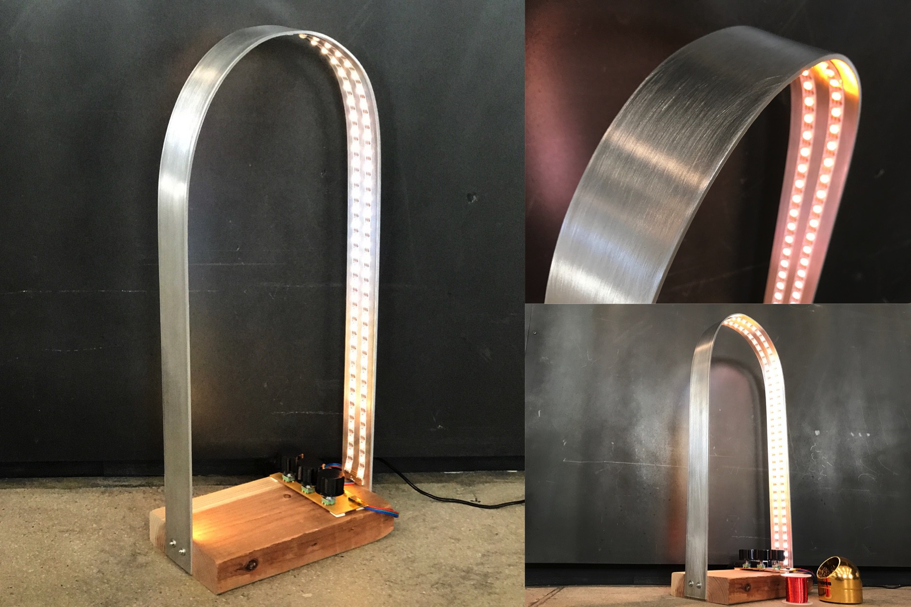
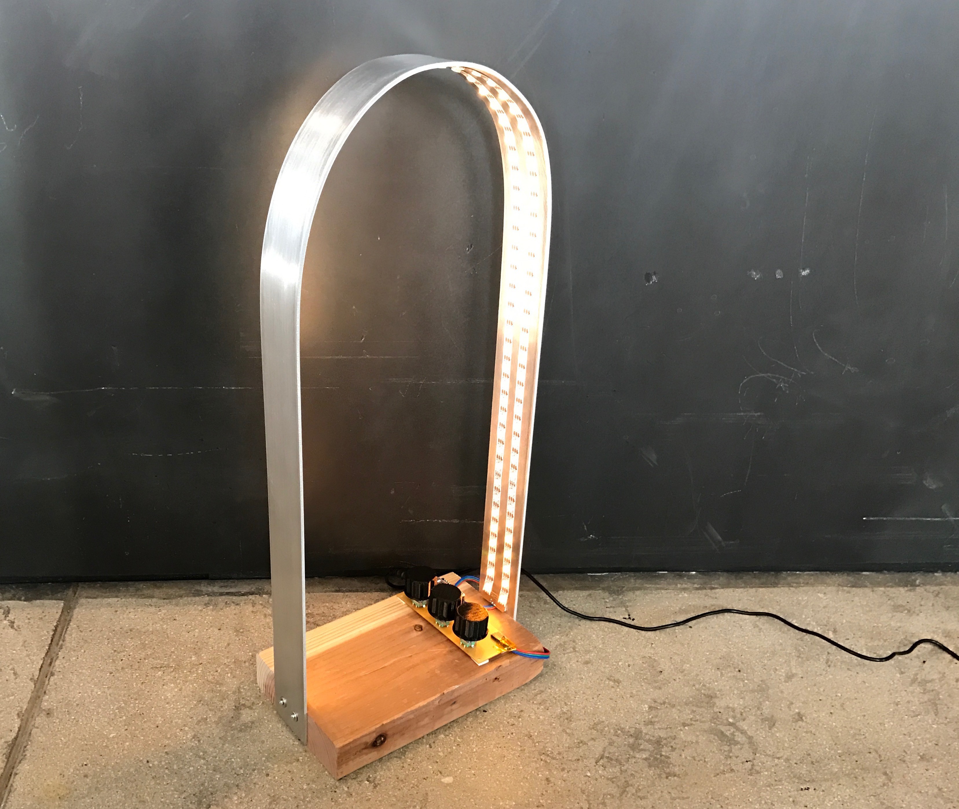
It turned out okay. With dynamic patterns on it, it really comes to life.
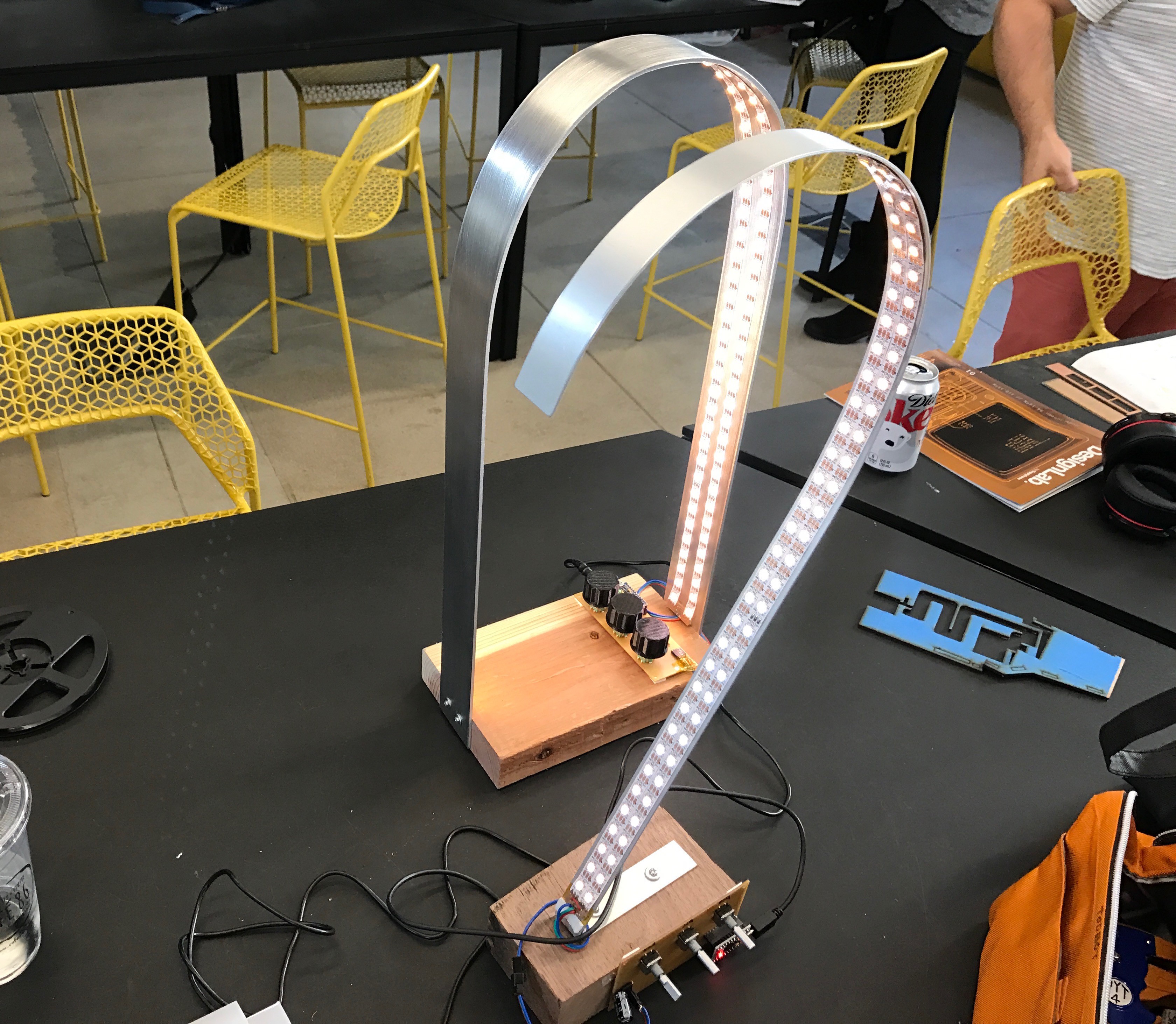
Here it is in size compared to lamp 1. About the same height but much more stable.
Next steps:
- Gain control over ShopBot to try out some wood-based ideas
- Mod this lamp to add diffusers
 todbot
Discussions
Become a Hackaday.io Member
Create an account to leave a comment. Already have an account? Log In.