Close
0%
0%

Standalone WiFi E-mail Notification Display

Displays the date, sender and subject of your e-mail in a non-intrusive way. Standalone, no running PC or special server required.

Similar projects worth following
This WiFi connected device talks directly to the server over POP or IMAP, reads the most important information about the 10 most recent e-mails and rotates this over this nice stylish display.
The design includes an RN131 WiFi module, ATmega644P, a nice HD44780 compatible white-on-black LCD display, capacitive touch buttons and a USB connection for setup. Everything fits in a nice shiny lasercut enclosure.

I made this in 2011. The idea comes from a friend with a busy job who suggested that after a long day at work answering all those work e-mails it would be nice to have a quick overview of his private e-mail without booting up his computer. I designed this as a non-intrusive solution to get a quick view of new e-mails. The device just sits quietly, connects to a POP or IMAP mailbox, requests the headers of the 10 most recent mails and stores this data. When you want to know if there are any new e-mails you just touch one of the buttons and the display lights up, showing the sender, date and subject of the 10 most recent e-mails in the inbox.

What's nice is that it's completely standalone and you don't need to have it connected to the computer or run a special server or something like that. It just talks POP or IMAP to the server.

It has a USB port to configure it. You connect it to the computer, run the configuration program, enter the WiFi and e-mail details and from that moment on it starts reading e-mails.

Finally made 3 pieces, one for him and two others for family members. The design is more or less made with production in mind but I never continued that because the cost price was too high, the RN131 WiFi module being the most expensive part.

Tools used:

  • Firmware written in C with AVR-GCC, using Eclipse as IDE.
  • AVR Dragon as programmer/debugger
  • PC software to configure the device written in C# using MonoDevelop. The software runs both on Linux and Windows.
  • Enclosure designed in Inkscape and lasercut/engraved by Formulor.
  • PCB and schematic in KiCad.

The firmware and configuration tool is available under the GPLv2 license. 

The bootloader is a slightly modified bootloader from the Sanguino project (diffrerent baud rate, different CPU clock and different uart used).  It's licensed under GPLv2 or later. 

The touch buttons use software from Atmel used in binary form. See the README file on the Mailnotifier-Firmware repository on GitHub for more details.

The enclosure and schematic/PCB are available under Creative Commons ShareAlike (CC BY-SA 3.0).

  • 1 × Roving networks RN131 Wifi Module
  • 1 × Atmega644P Microprocessors, Microcontrollers, DSPs / ARM, RISC-Based Microcontrollers
  • 1 × Displaytech 204A White on black display 20x4 D44780 compatible
  • 1 × FT232RL Semiconductors and Integrated Circuits / Misc. Semiconductors and Integrated Circuits

  • Prototype: video

    Springuin07/26/2014 at 19:16 0 comments

    Now there is also a small video about the prototype, see here: http://youtu.be/ZzTIbmoQ0nk

  • Prototype pictures

    Springuin07/26/2014 at 19:07 0 comments

    Prototype pictures!

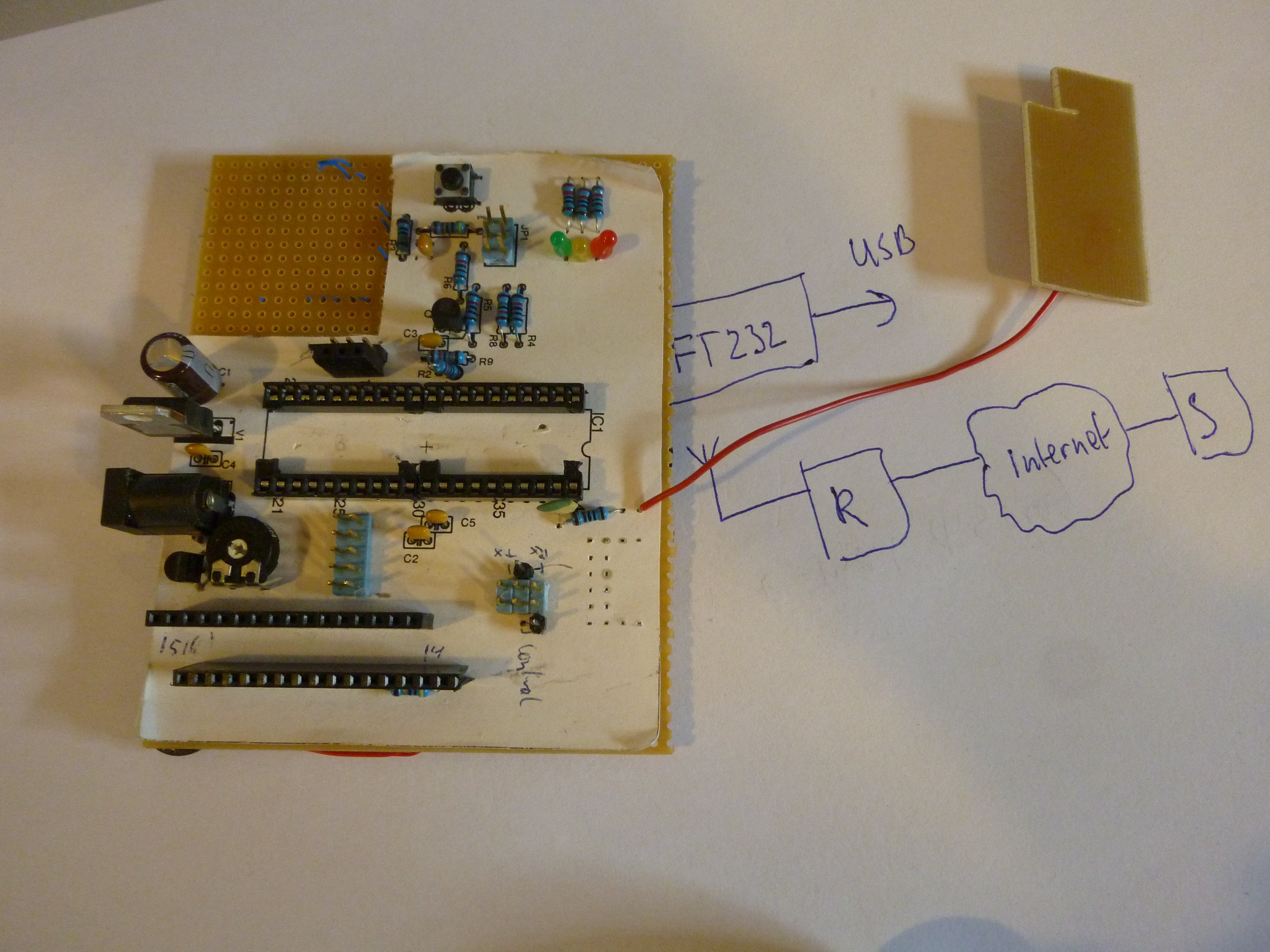
    For all devices I make I start with a prototype on these kind of prototype PCB's. Single sided, with separate islands. Some people use stripboard but I prefer this because you don't have to break tracks and are not limited to one direction.

    You see the valuable parts are removed. The wifi module was in the top left corner, connected with wires, floating above the PCB. The microcontroller was in the socket in the middle. On the right side, just below the microcontroller you see the holes where the MM232 module was (small module wih an FT232 chip). And the display is also removed. I used most of these parts in one of three units I produced.

    The finished device has four touch buttons, the prototype only one. I figured that if one would work, four buttons would work just as well (and it did).

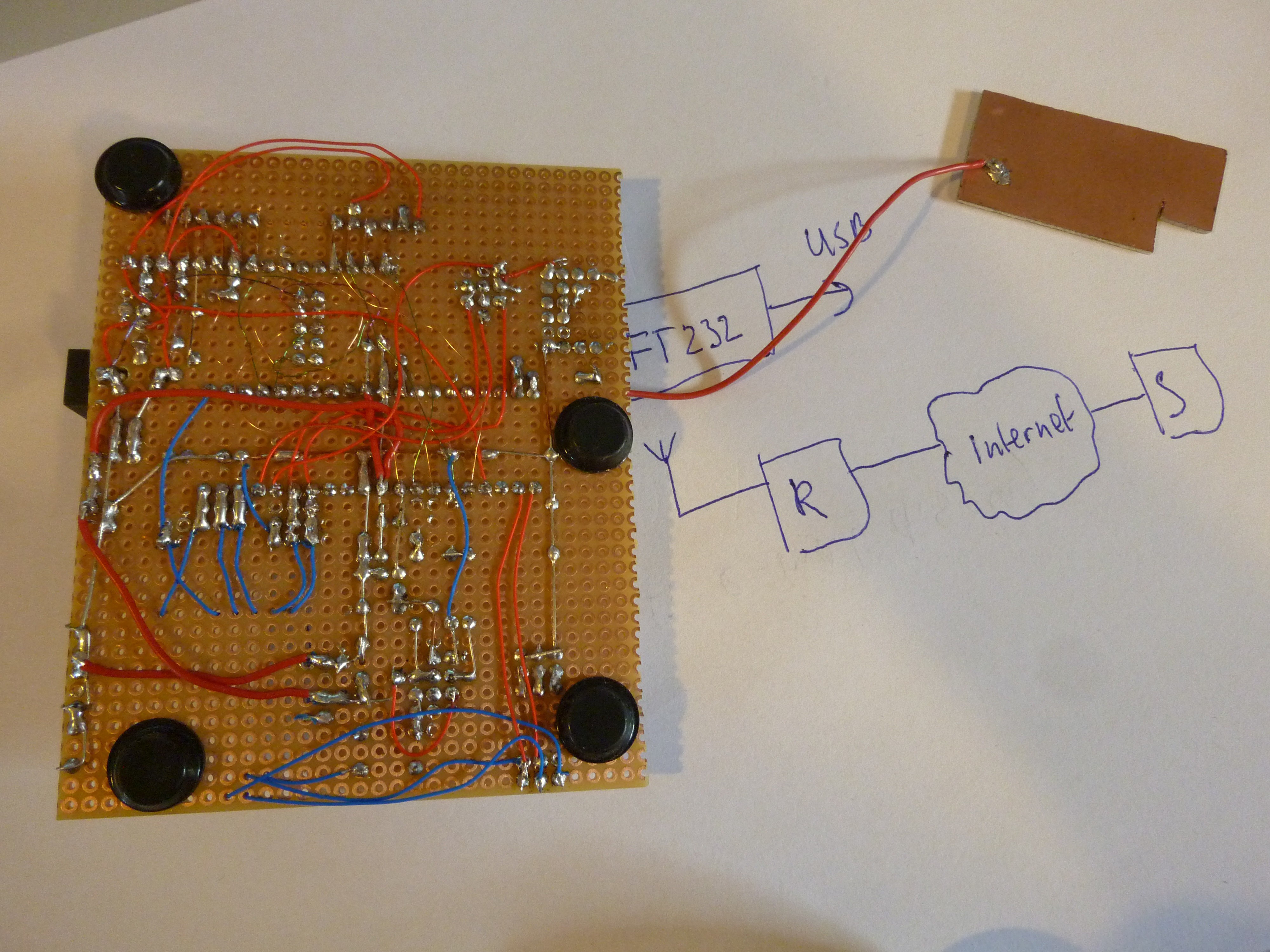
    The wires are on the bottom. The red and blue wires are 32awg kynar wires: solid core, really thin and a little hard to strip. The tiny wires are RoadRunner wires: thin wires with an isolating coating. The coating is removed by keeping a drop of tin on your soldering iron and sticking the wire in that hot drop of tin. The coating melts and you can solder the wire.

    Nowadays these thin wires are my preferred method of making these prototype boards. It's the fastest solution for me.

  • System structure picture

    Springuin07/26/2014 at 18:49 0 comments

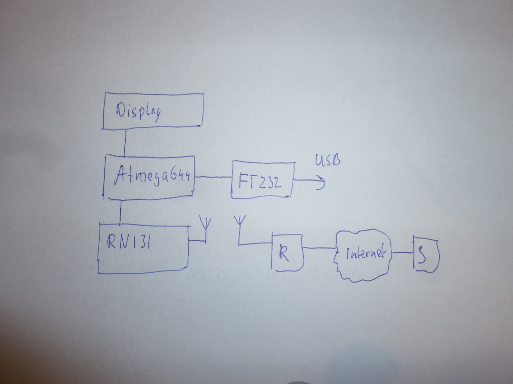
    Here is a picture of the system structure

    I chose an ATmega644 because it has two serial ports. I needed that because the RN131 uses one and the FT232 uses the other one. 

    The RN131 was at that time the best available solution for WiFi. Although, it did for example not support all types of wireless networks. If I remember correctly WEP64 was not possible. Not that you'd want WEP64 as encryption for your wireless network, but that's a different thing. Another thing I noticed in a different application is that the RN131 dropped characters if the WiFi signal strength was low.

    The display is a nice DisplayTech 204A; 4 lines of 20 characters, the chosen version has a black background and white text, really nice. The picture of the project doesn't do right to the beauty of the display.

    An FT232 is more or less your standard choice for USB to serial. It just works, it's simple to incorporate in a design, it is supported on all operating systems and, maybe because of all these reasons, really widely used.

  • YouTube video nr. 1 uploaded

    Springuin07/26/2014 at 18:23 0 comments

    I've uploaded a YouTube video that gives a quick overview of the system structure: microcontroller, wifi module, display and USB. Watch it here: https://www.youtube.com/watch?v=QpGKtC0IhtE

View all 4 project logs

Enjoy this project?

Share

Discussions

Rosmianto Aji Saputro wrote 02/20/2016 at 14:17 point

I did really enjoy exploring this project. I learned a lot about integrating various libraries and parts.

Thank you..

  Are you sure? yes | no

Dushyant Ahuja wrote 09/12/2014 at 14:29 point
The cost could probably be reduced by adding Ethernet instead of Wifi....

  Are you sure? yes | no

Springuin wrote 09/12/2014 at 18:16 point
Yes, a W5100 or ENC28J60 are much cheaper than a wifi module but I wanted it to be wireless so you could place it anywhere you want without having to worry about tripping over an ethernet cable :-)

  Are you sure? yes | no

Similar Projects

Does this project spark your interest?

Become a member to follow this project and never miss any updates