Close
0%
0%

Paperino

An easy-to-use, open source micro ePaper shield for the Particle & Arduino community

Similar projects worth following
What do you need for your next IoT project? Basically it's connectivity and low power I/O. There are enough projects, that got the connectivity side covered. Low power display and signage is kind of hard to find. But there's a perfect solution for that: E-Ink or ePaper displays!
We love ePaper displays. They are nice to look at and only consume power while changing their contents. No need to refresh them unless you want new information. Perfect for ultra-low power and battery driven projects!
However, integrating an ePaper display into your project can be complex due to the need for several high voltages and waveforms.
Our aim is to simplify the use of ePaper and make them just as accessible as LCDs.
You just supply 3.3 volts, hook up your SPI bus and we do the heavy lifting for you.
All hardware and software is open source. Files can be found in the respective hardware and software repos.

The plan

We got the first prototypes and the Arduino library going.

Now we want to make it available for all makers and electronics enthusiasts out there. Here we want to document our successes and failures in getting Paperino past the prototyping phase and in low volume production. If you want to pre-order a Paperino our just support us in our efforts check out our campaign on Crowd Supply.

But first let's take a deeper look into Paperino:

The display

We use a glass-free ePaper display from Plastic Logic. It weighs 1.2 grams and is only 0.5 mm thick (we're German so we use the metric system, sorry ;-)).
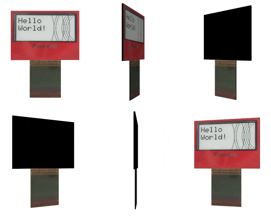
For those interested in the details here's some of the display's spec:

  • Resolution: 148 x 70 px
  • Pixel density: 150 ppi
  • Grey levels: 4
  • Weight: 1.2 g
  • Thickness: 500 µm
  • Power consumption: 4.5 mA (mean current for typical image update, update time ~0.8s)
  • Operating conditions: 0°C .. 40°C
  • Storage conditions: -25°C .. 50°C

The drive module

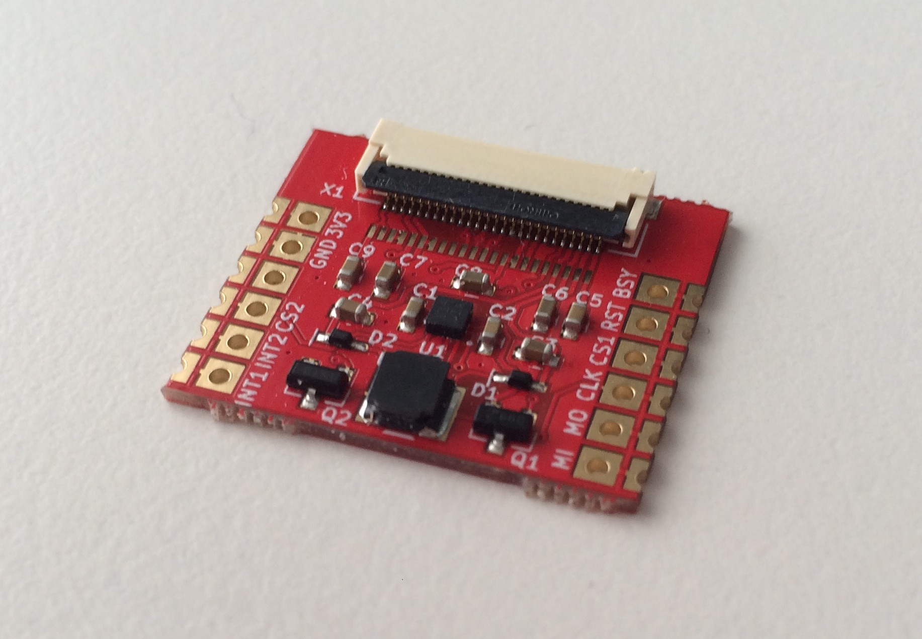
The drive module is the heart and soul of Paperino (aside from the display, of course). It contains the booster circuit needed to generate the high voltages to drive the display (for those who want to know: we generate +17/-25 volts with the booster and the display's driver chip uses those to generate additional +/- 15 volts).

We use half-cut holes to mount the module to our shield and breakout board. You could use this module just like that for your next low power project. Just drop the module down, connect a display and you're good to go. The schematics and KiCad layout files are open source, so you could also check out our repository and do your own layout.

The module also sports an accelerometer for tap-sensing (a kind of touchscreen emulation, if you will).

Read more »

paperino_module_BOM.xlsx

BOM for the drive module

sheet - 7.73 kB - 05/06/2017 at 08:26

Download

paperino_module_BOM.ods

BOM for the drive module

spreadsheet - 12.88 kB - 05/06/2017 at 08:26

Download

  • Prototyping for new display sizes

    Markus10/06/2017 at 08:12 3 comments

    After fulfilling the campaign we were thinking about where Paperino could be going. The feedback we heard the most was that the display was too small. At the time we choose the 1.1" display because it was the only one we could get at a reasonable price from our display's manufacturer. Now after the successful campaign we talked to the display manufacturer again and we might be able to source other/bigger displays from them.

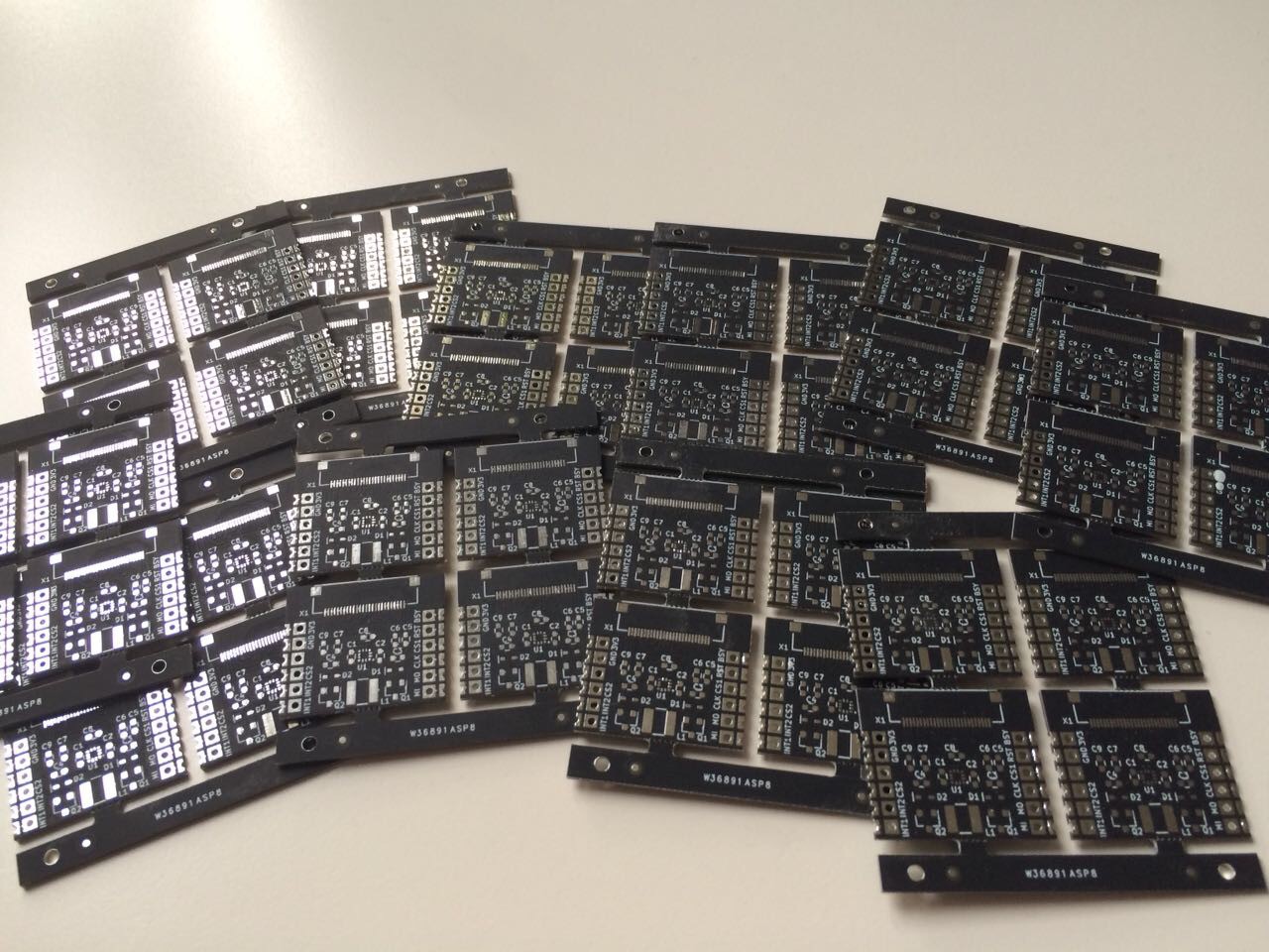
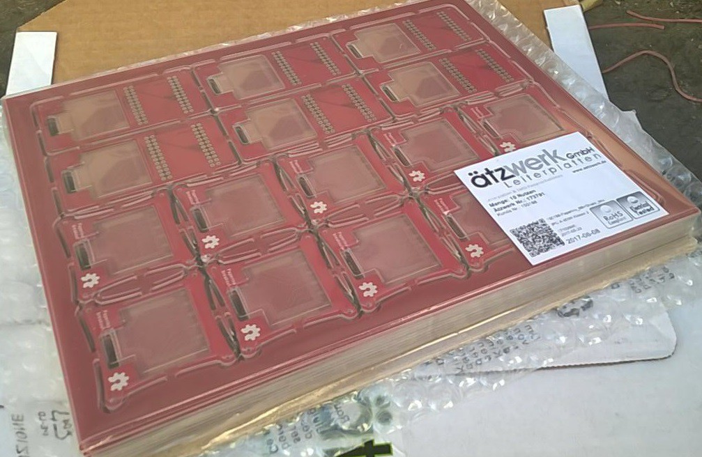
    The only thing we have to adjust is the display pinout. The layout change was done pretty quickly and we sent the Gerbers to the fab to get some nice matte black PCBs.


    Yesterday we assembled the first panel and it's working fine with a 2.1" display:

    There's still some work to be done on the software side of things. For example we want the library to have an auto-detect function. If we ship the same hardware with different displays, we want to make sure the software detects which display is plugged in and automatically loads the right height and width settings.

  • Assembly and shipping

    Markus07/23/2017 at 09:03 0 comments

    It is finally done. We finished assembling and testing the Paperinos for our crowdfunding backers and it was more work than we thought. Why did nobody ever tell us that hardware was hard (I'm kidding, everyone says that all the time).

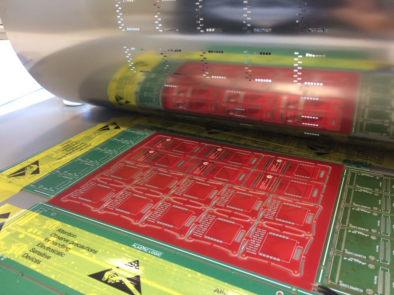
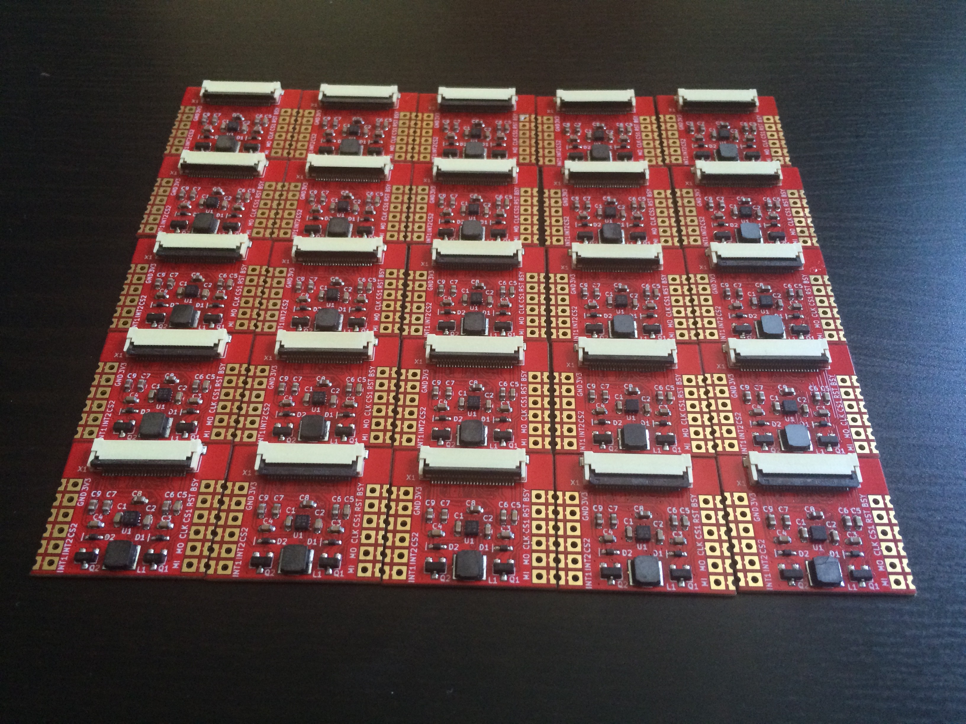
    Let me walk you through some of the assembly. We got the modules assembled in China and ordered the breakout boards and shield in panels. Also we got the connectors for the shield and breakout, a stencil for the panel, a frontcover to stick on the display and most importantly the displays.

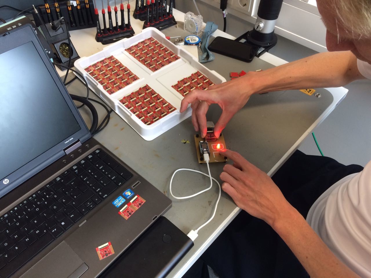
    All modules were tested using our testing rig.

    With this huge ( 550x550 mm!) stencil we applied the solder paste to the panels to solder the modules and SMT header on there.

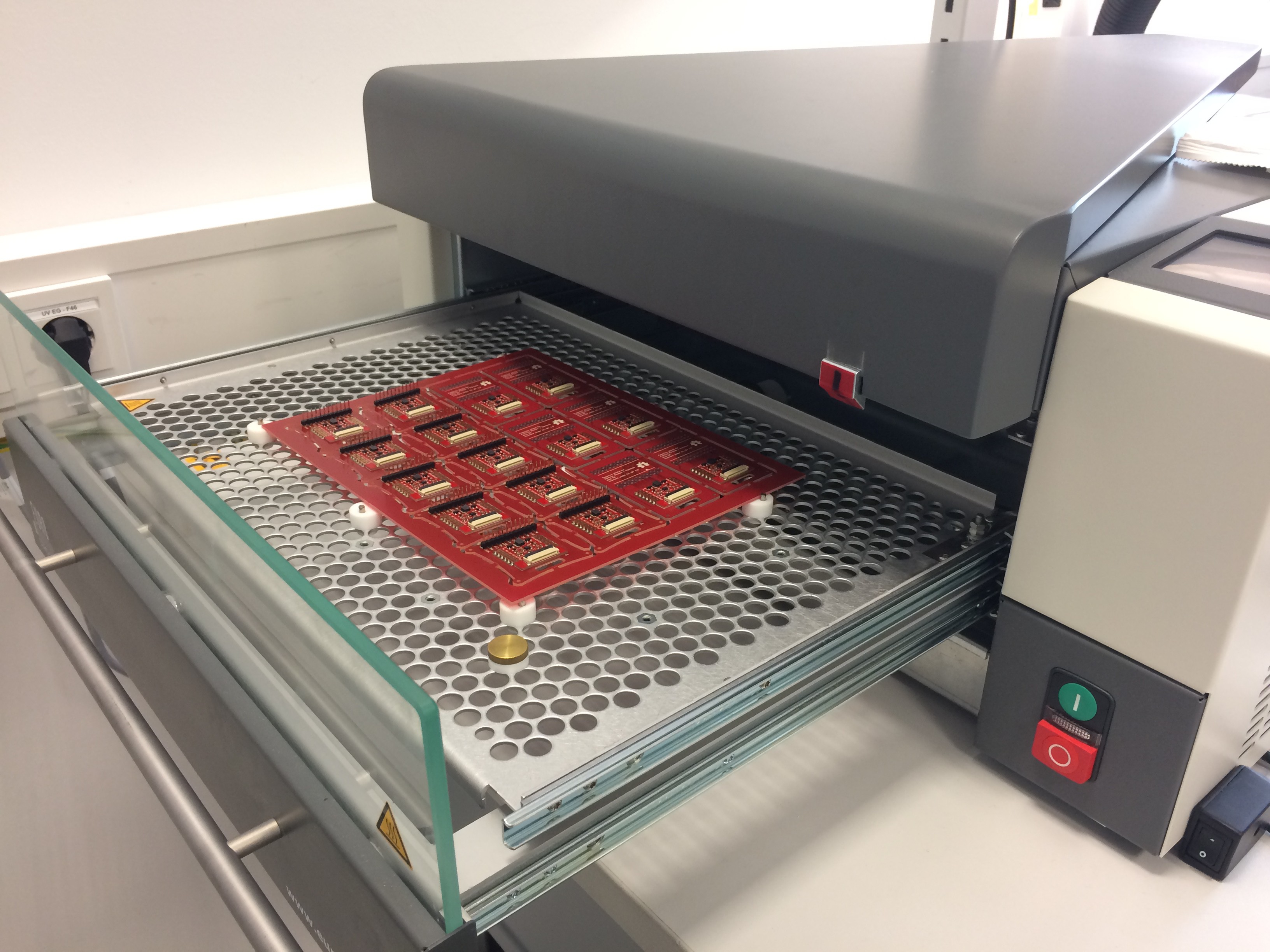
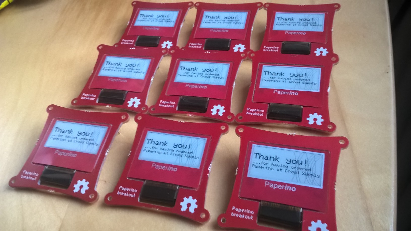
    The panels were reflow soldered in the oven. We then had to break all the boards out of the panel, stick the displays in, put frontcovers over the displays and test the end product. Finally our product was finished:

    We packed it all up and sent it to CrowdSupply, who will take care of the fulfillment for us. We're quite proud that we made it and will be able to deliver to our backers on time.

  • Manufacturing update

    Markus06/11/2017 at 10:20 0 comments

    Our CrowdSupply campaign has been successfully funded (YAY!) and now we're working on fulfilling the pledges.

    In our first pilot run we learned that we didn't want to assemble the boards ourselves. We ordered a small run of assembled drive modules to evaluate the contract manufacturer (we didn't work with them before and it seemed risky to give them all this money without evaluation). We're pretty pleased with the result and will now place the order for the remaining drive modules.

    Also the PCBs and connectors for the shield and breakout boards arrived. We decided to go with stacking headers for the shields, so you can plug several Particle shields together (we like to use the LiPo battery shield + our Paperino shield for example). If you don't need to stack shields and don't like the form factor (you can't put the board as flat on the table then), you can just clip the headers yourself.

    So things are looking good on the manufacturing end so far. We'll keep you posted.

  • E-paper basics 3: a bonus update mode (for animations)

    Markus05/17/2017 at 12:23 0 comments

    Our first log on e-paper basics described two update modes:

    • full update (whole display, flickering, best optical performance)
    • partial update (only select pixels, no flicker, less power consumption, okay optical performance)

    As we hinted in the log there is another update mode, we did not mention yet.

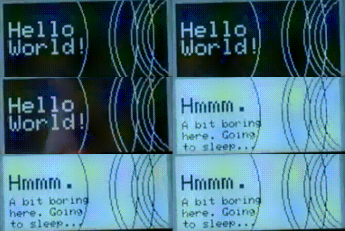
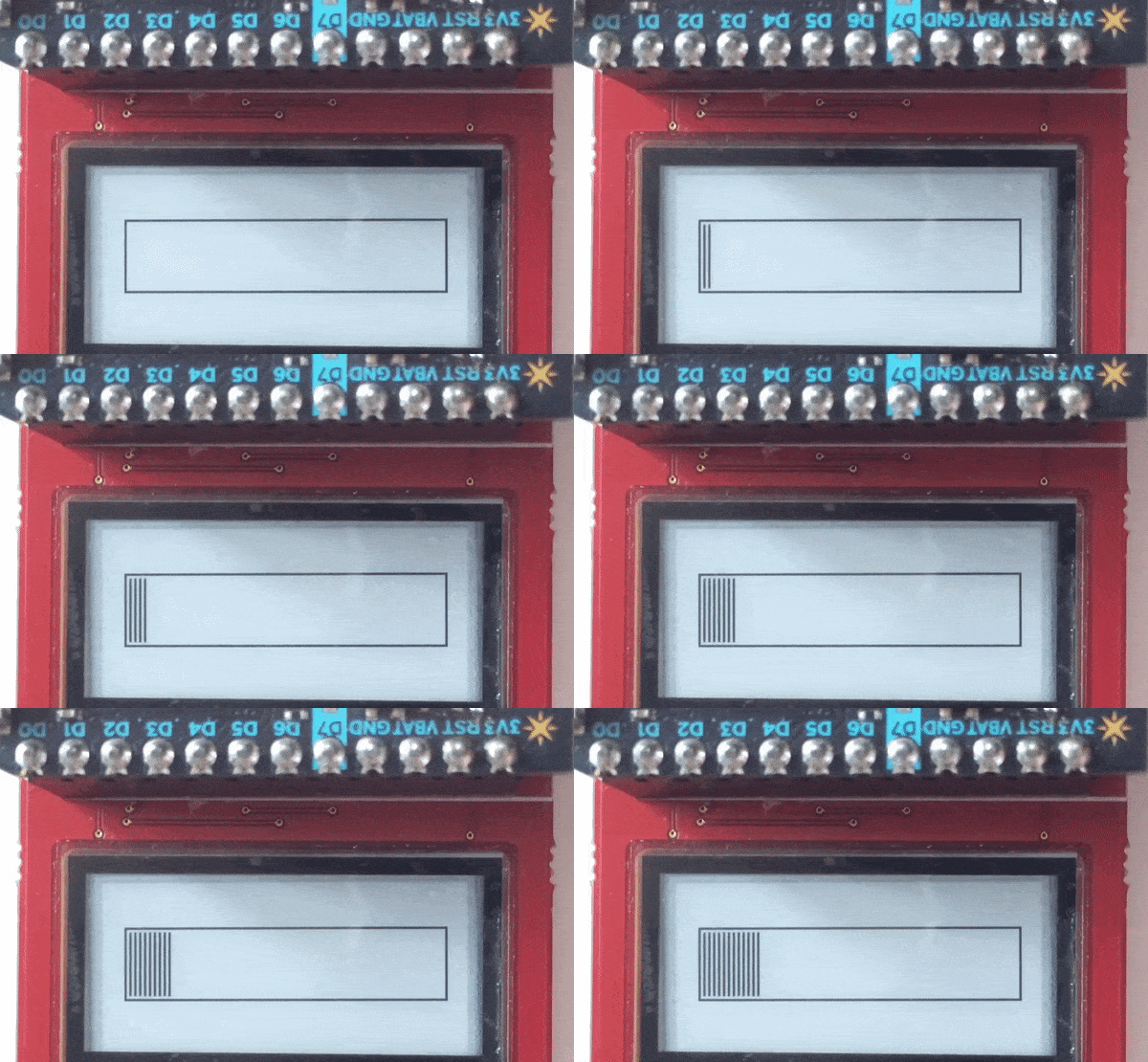
    Both full and partial update take 0.8s at room temperature to drive the display. Here is a progress bar using partial updates:

    Okay, so that takes a while. In general, e-paper displays are not suited for animations but rather for static content that only updates once in a while.

    But there is a bonus update mode in our display's controller for exactly that. The mode is called "mono" or "fastPartial". It only drives pixels black and white (so no four gray levels in this mode) and takes around 250ms for an update.

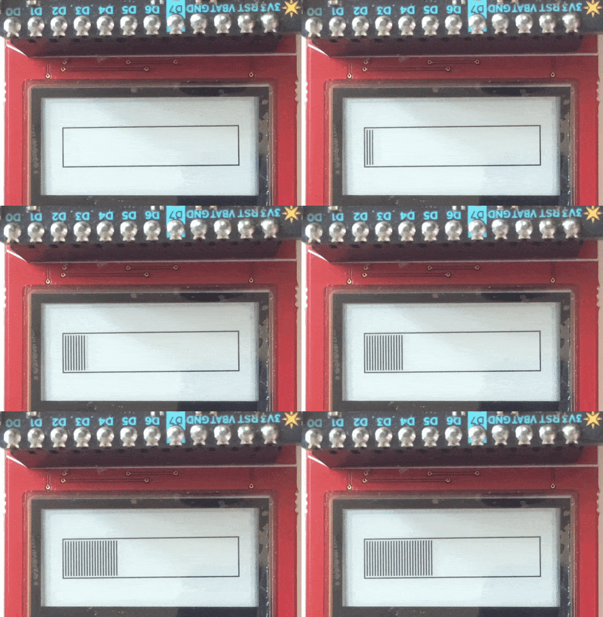
    The same animation as above with the mono update mode looks like this:

    Not exactly suited for gaming (it's about 4 FPS), but definitely better than our standard 0.8s.

    The mono update in a nutshell:

    • fastest at around 250ms
    • lowest power consumption
    • worst optical performance

  • E-paper basics 2: Gray Levels

    Markus05/14/2017 at 09:56 0 comments

    This time in e-paper basics we want to talk about gray levels. To understand gray levels we need to take a quick look into the inner workings of EPDs (electrophoretic displays or commonly known as e-paper).

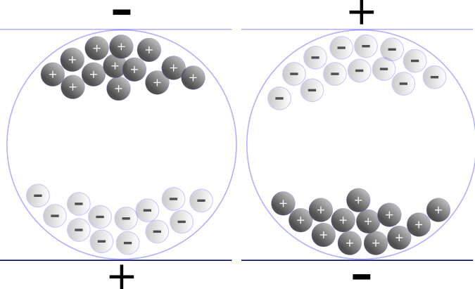
    by Senarclens; CC-BY-SA 3.0

    (by Senarclens; CC-BY-SA 3.0)

    Our display roughly consists of a backplane (a transistor matrix on a plastic substrate, pretty cool stuff btw) and so called media laminated on top of it. The media is the part that we see. Inside the media are charged particles (black and white ones). We use the transistor array to charge capacitors, which generate electric fields. These fields make the particles move (as shown in the picture above).

    In the picture you can see the two extreme cases. In the left one all black particles are on the top; we can see a black pixel. On the right side all white particles are on top; we see a white pixel. Now, what happens when you don't drive the particles to the extremes but mix them in the middle? You guessed it: You get different shades of gray.

    Most display manufacturer only let you use black and white. We are very happy, that our display supplier gives us the freedom to also use shades of gray.

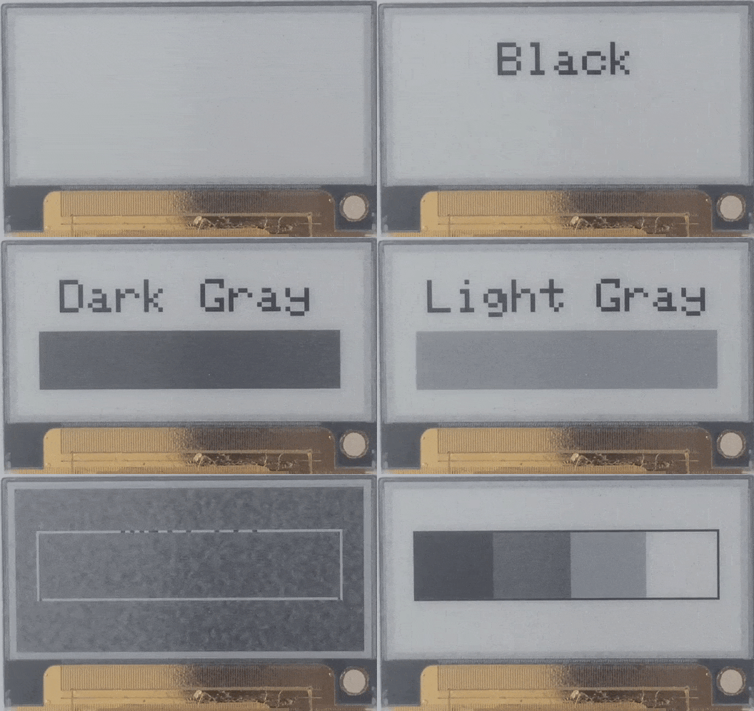
    The display controller let's us drive four different gray levels (otherwise known as 2-bit gray scale) and they look like this:

    (If you read our last e-paper basics on update modes you notice how we use both full updates and partial updates in this demo.)

  • E-paper basics 1: Update modes

    Markus05/11/2017 at 16:30 0 comments

    Now that our prototypes are working, we want to take a closer look at our e-paper displays and their features. Today we want to talk about update modes. What are update modes? Basically they are the way how the displays content is driven.

    The standard mode is the so called "Full Update".

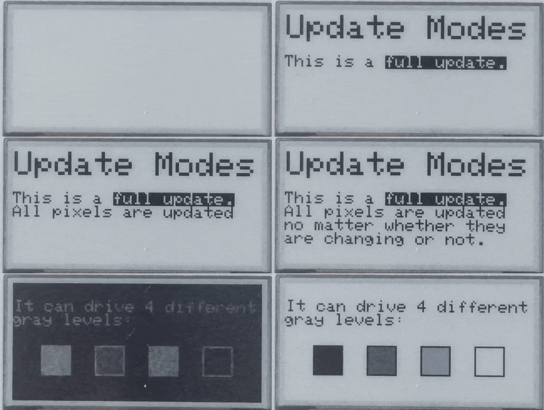
    It looks like this:

    All of the displays pixels are driven to black, then to white, then to their specific target gray level. This results in a lot of flashing, but as we drive the pixels to their extremes, we get a nice, defined end result.

    Most e-paper displays only let you use the full update mode. This is mostly due to restrictions given by the display's manufacturer.

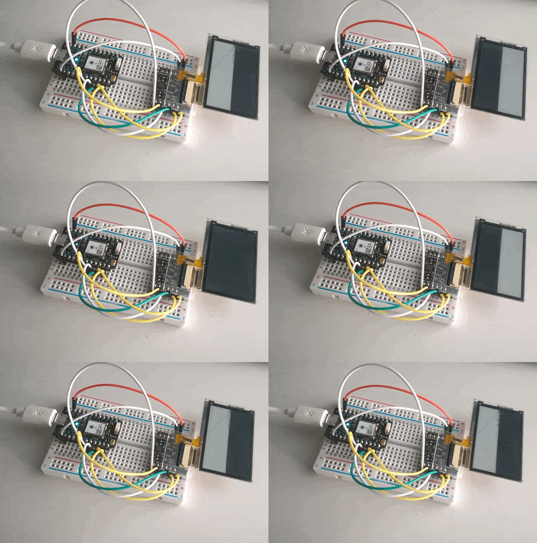
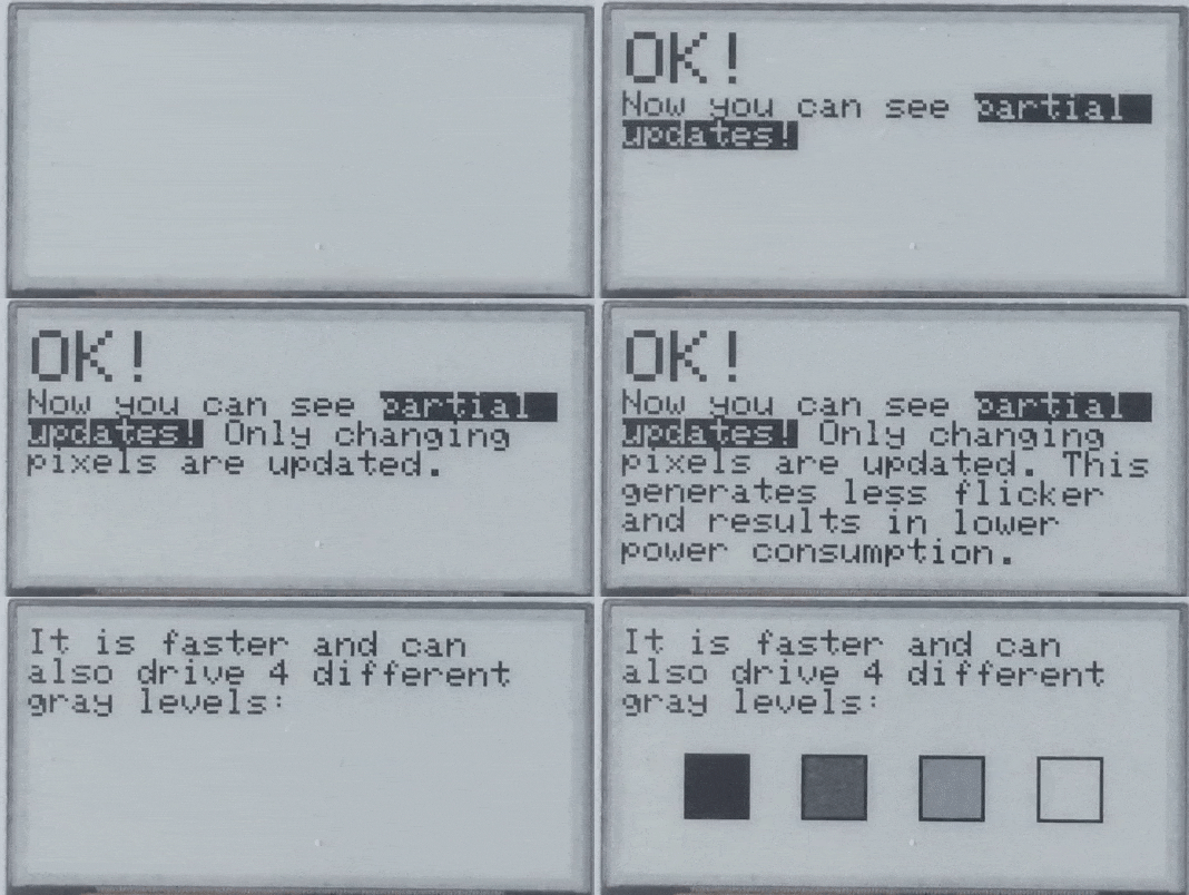
    But Paperino is different. We also support the so called "Partial Update". In this mode only the pixels that really need to change are driven. This results in less flicker and less power consumption and looks like this:

    I know I wrote "It is faster..." on the display but technically it isn't. Both update modes take about 0.8s for an update at room temperature. We have a third update mode, which is faster, but I'll talk about that in a future update.

    So why don't we use partial updates all the time? Why bother with all the flickering? The optical performance of a full update is way better. You get better contrast and a well defined image. If you use partial updates too often, you'll get the so called "ghosting" effect. Ghosting looks like old display content is burned in and shows through in the new image. You can get rid of ghosting by doing another full update.

    So that's it for update modes (spoiler alert: it isn't! There is one more to come.). In the gifs you can also see the 4 gray levels we advertised in the project details. We'll talk about them another time.

  • 2nd pilot run = success!

    Markus05/08/2017 at 06:10 0 comments

    So our first pilot run was just kind of successful. The circuit itself works fine but we had the connector pinout flipped. We quickly fixed it and ordered a new pilot run, which has arrived now.

    To save money we didn't order the PCBs in a panel this time and did opt for a HASL finish instead of ENIG (now our prejudices are confirmed: ENIG looks way better than HASL on red silkscreen). The end product will definitely sport a flashy looking ENIG finish.

    We assembled the circuits using our stencil (check out our log on assembling the first pilot run, if you don't already know it). We used the stencil for one PCB at a time instead of the whole panel. This time we didn't challenge our patience and only assembled four circuits.

    In the end we connected a display to the assembled circuits and tested them with our rig:

    We're really happy that we were able to qualify our design for low volume production.

  • I guess that means we need another pilot run

    Markus05/02/2017 at 06:52 0 comments

    A quick recap: We build a pogo pin test rig for our project and got the pilot run for volume production assembled.

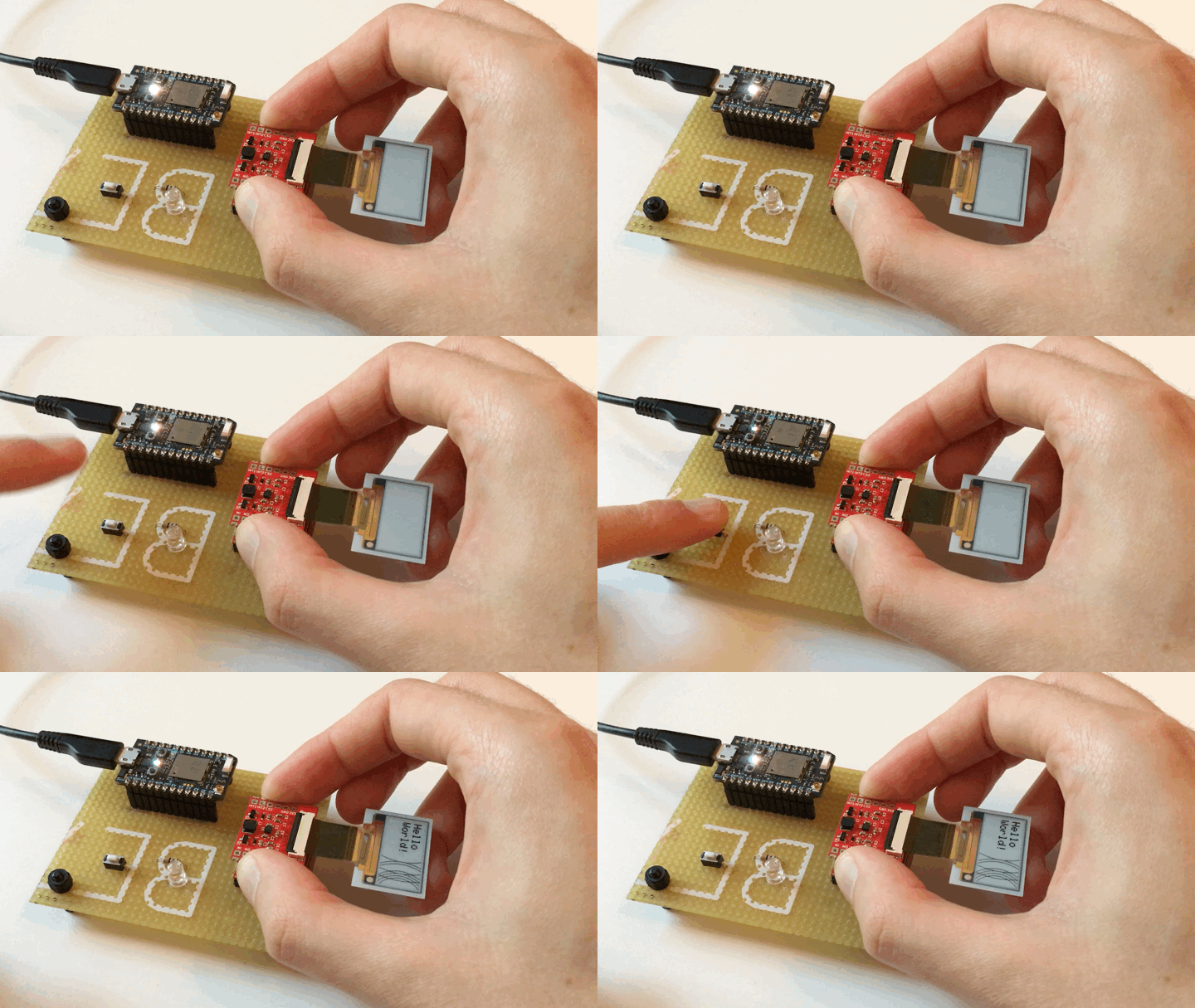
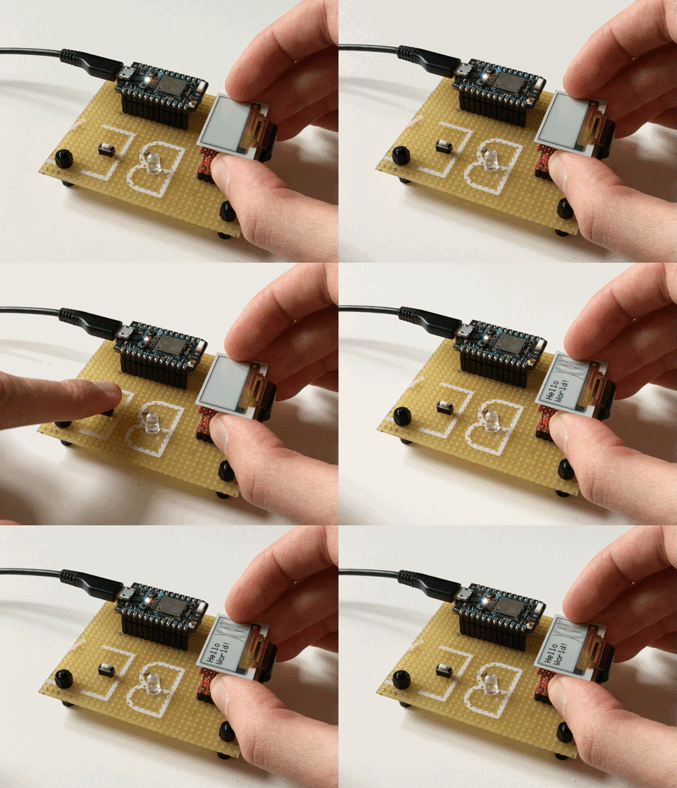
    We then got working on the code for our test program. Here is what testing a module SHOULD look like:

    You connect a display to the module, push the module on the pogo pins, push the button and then the display should do an update. Except for us it didn't. We began investigating and ironed out some kinks in the firmware (from prototype to pilot we changed to another SPI bus) and it still didn't work. With further investigation we found our rather dumb mistake: We flipped the pinout on the display connector. All signals are there in the right order, just mirrored.

    The connector we use is a dual contact connector, meaning there are contacts on the top and bottom. So in our case it is possible to make up for the flipped pinout by also flipping the display. You then just need to do some finger acrobatics and it works:

    Besides the dumb mistake we could confirm our pilot working (we did some layout and BOM optimization).

    The mistake was fixed pretty quickly and we already ordered another pilot run, keeping our fingers crossed this will be the last one.

  • Assembling the pilot run

    Markus04/30/2017 at 16:02 6 comments

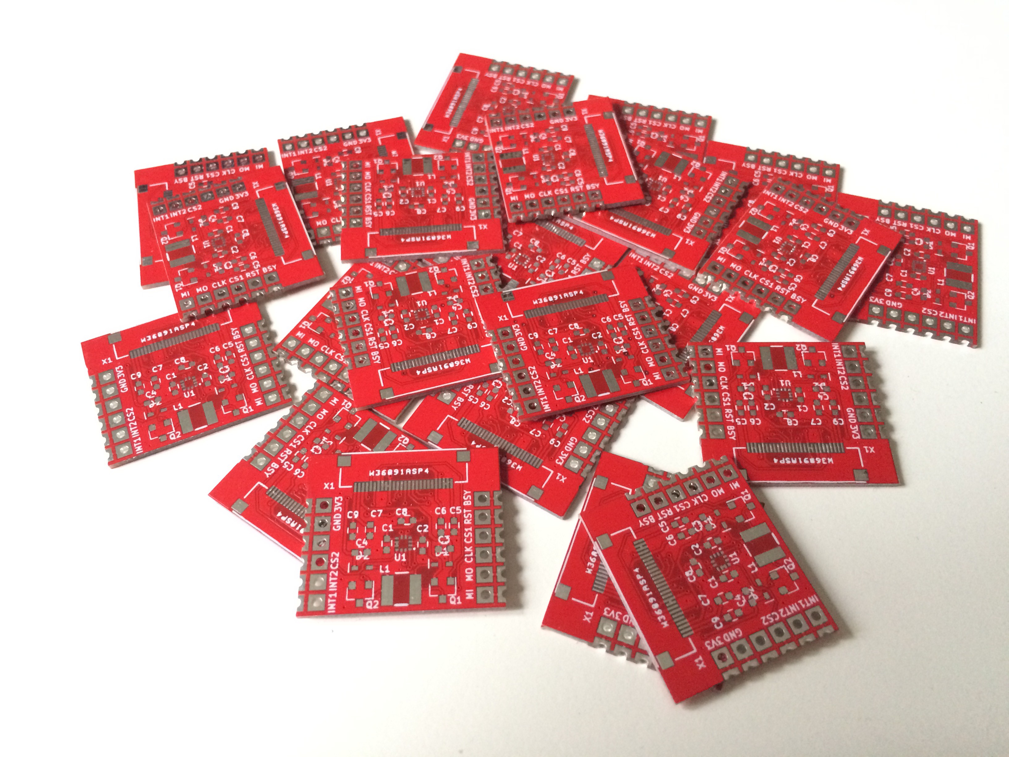
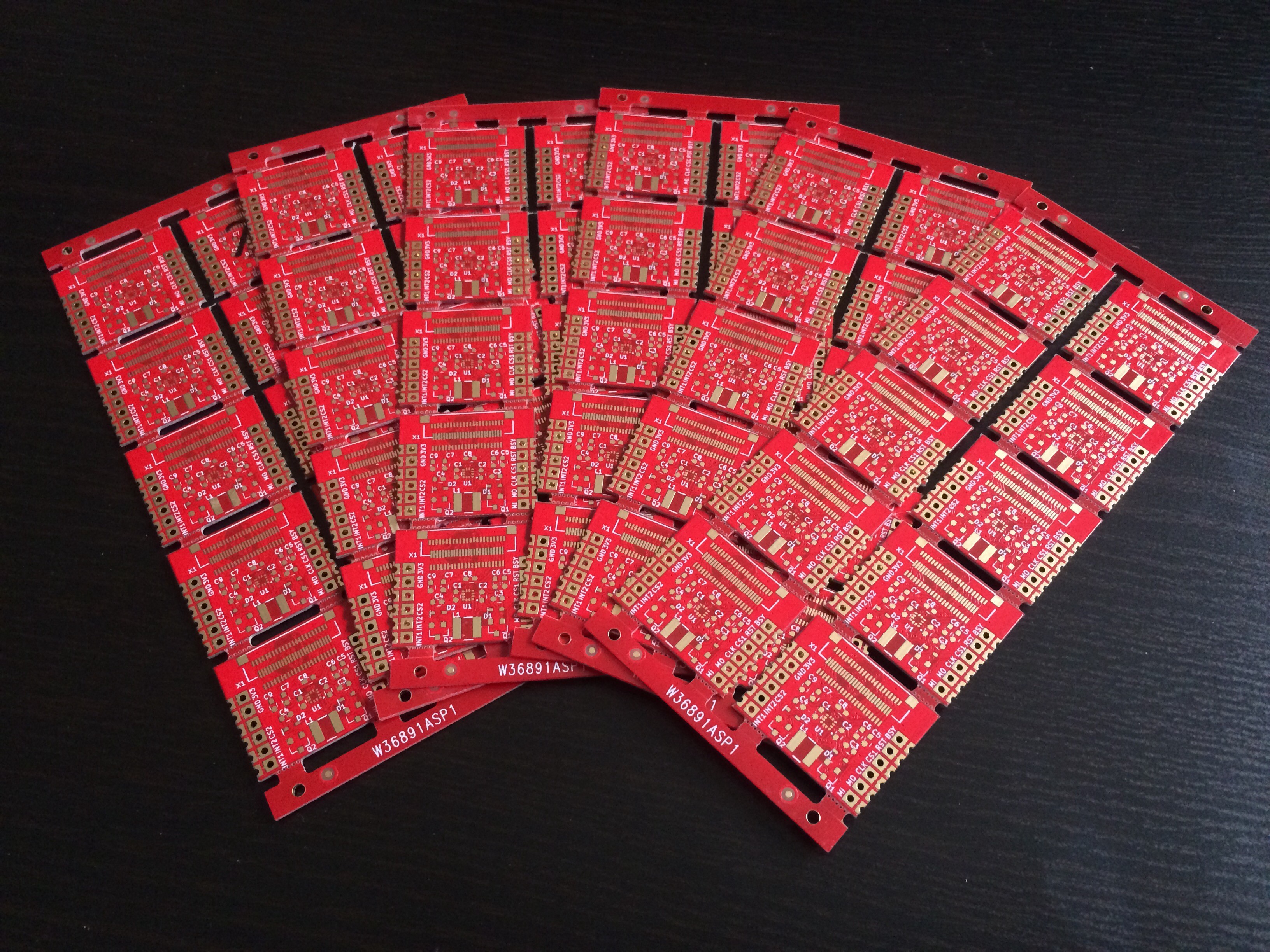
    Yay! Our pilot run PCBs arrived. Finding a PCB manufacturer was not as easy as we hoped, mainly due to our special demands like

    • red solder mask
    • ENIG finish (it just looks great with the red solder mask, right?)
    • 1 mm PCB thickness
    • half-cut holes / castellation (this was the deal breaker for most manufacturers)

    Also we really didn't want to set the panels ourselves so having it done by the manufacturer was also a big plus.

    And all that of course for the cost of under 1$/piece in volume (the pilot run was not that cheap of course).

    In the end we had them made at PCBway.com (that's a ref link, just so you know) and we are pretty pleased with the results.

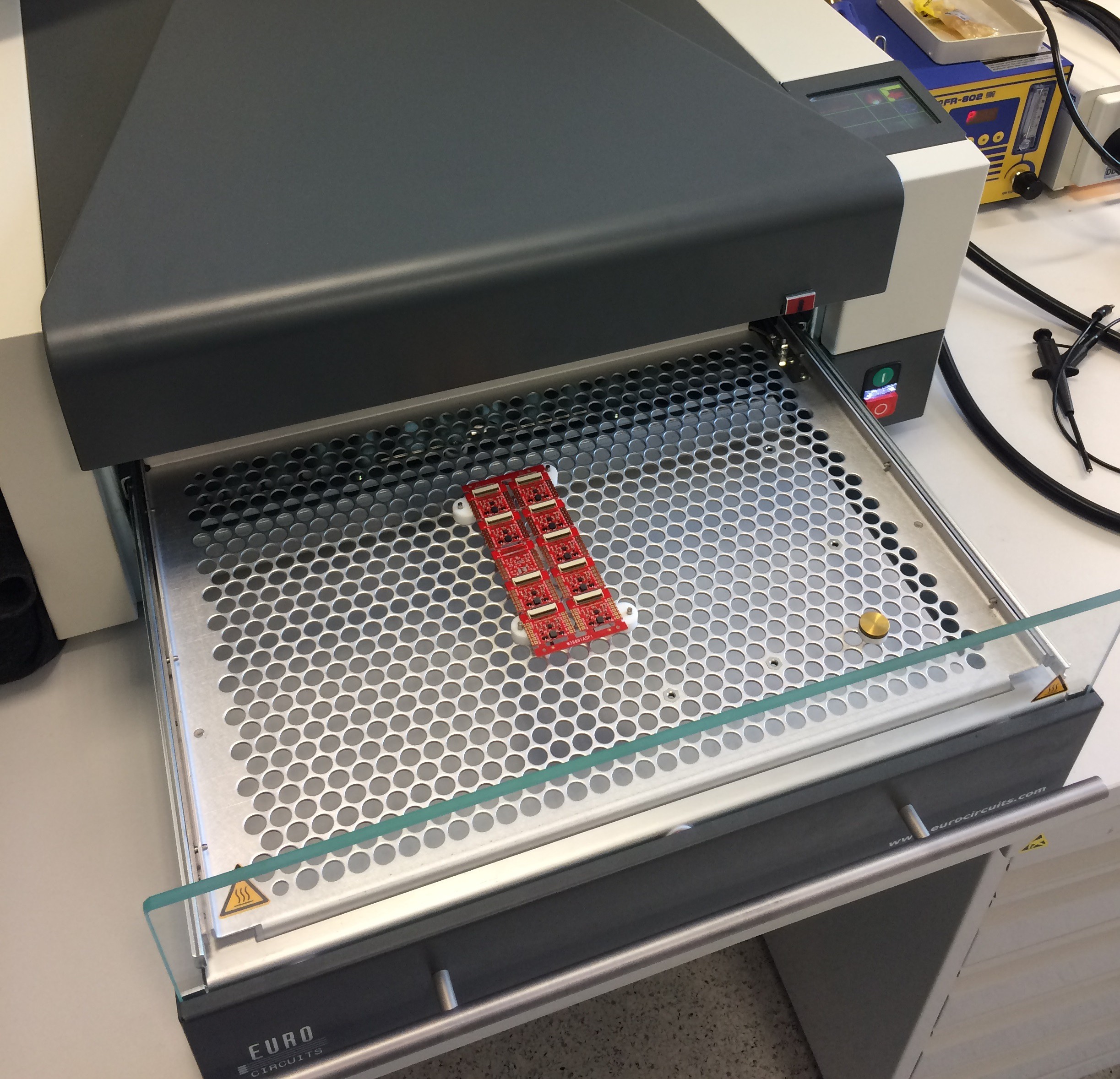
    We ordered them in handy 2x5 panels, because we thought 10 pieces was a good number of circuits to handle at a time.

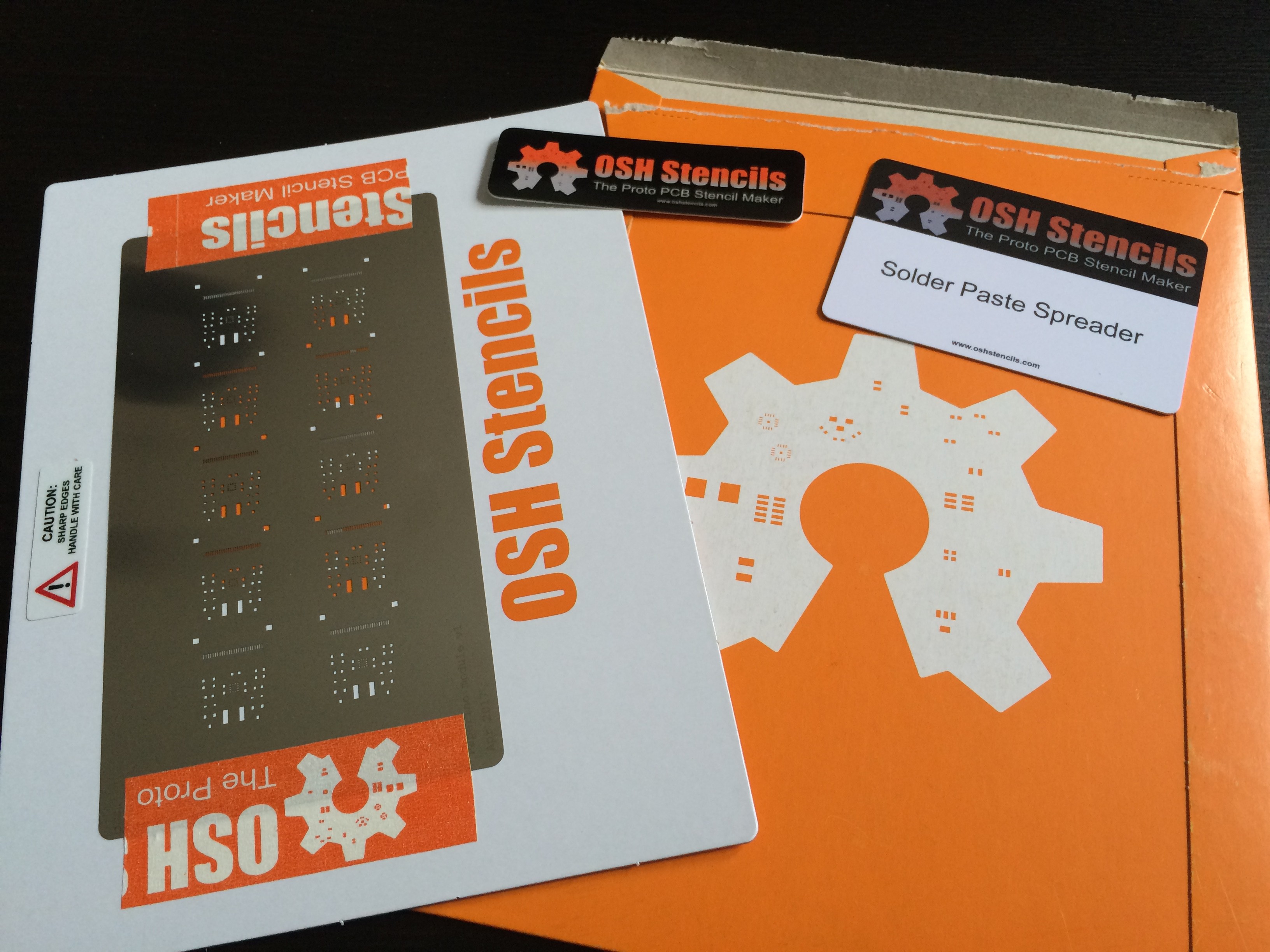
    We want to assemble the pilot run ourselves so we got a stencil at OSHstencils.com.

    We applied the solder paste and placed the components manually using tweezers. Placing the components was much more exhausting then we expected (10 circuits was a bit too much, to be honest).

    We put it in our reflow oven (actually it's the company's we work for):

    And out came 9 drive module assemblies (we messed up the solder paste on one circuit so we only assembled 9).

    So yeah, we're pretty pleased with the results and will now work on a test program for our rig and then hopefully qualify the pilot run for mass production.

  • Building a test rig for the module

    Markus04/29/2017 at 14:05 0 comments

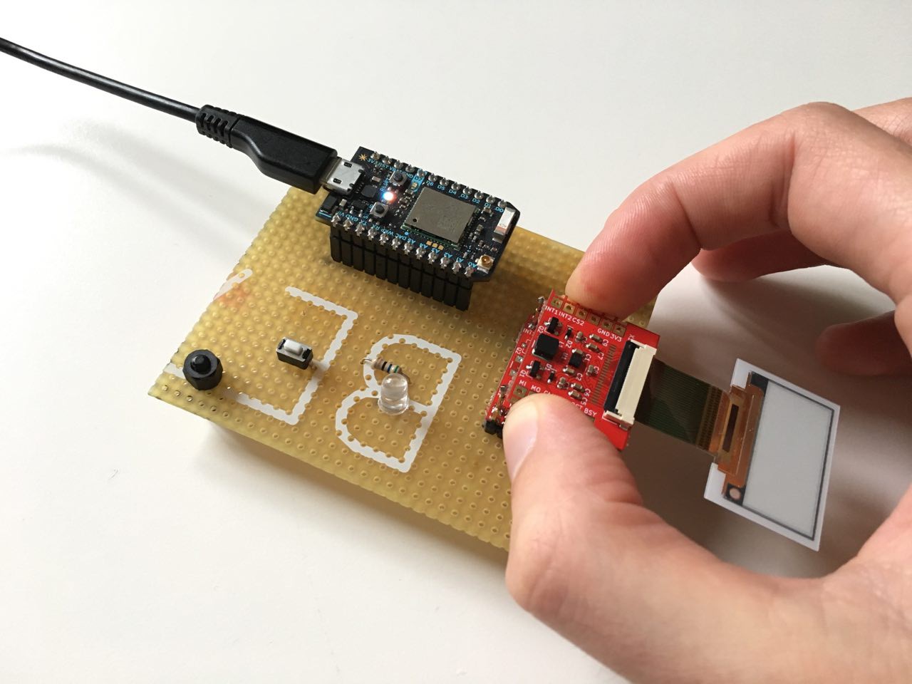
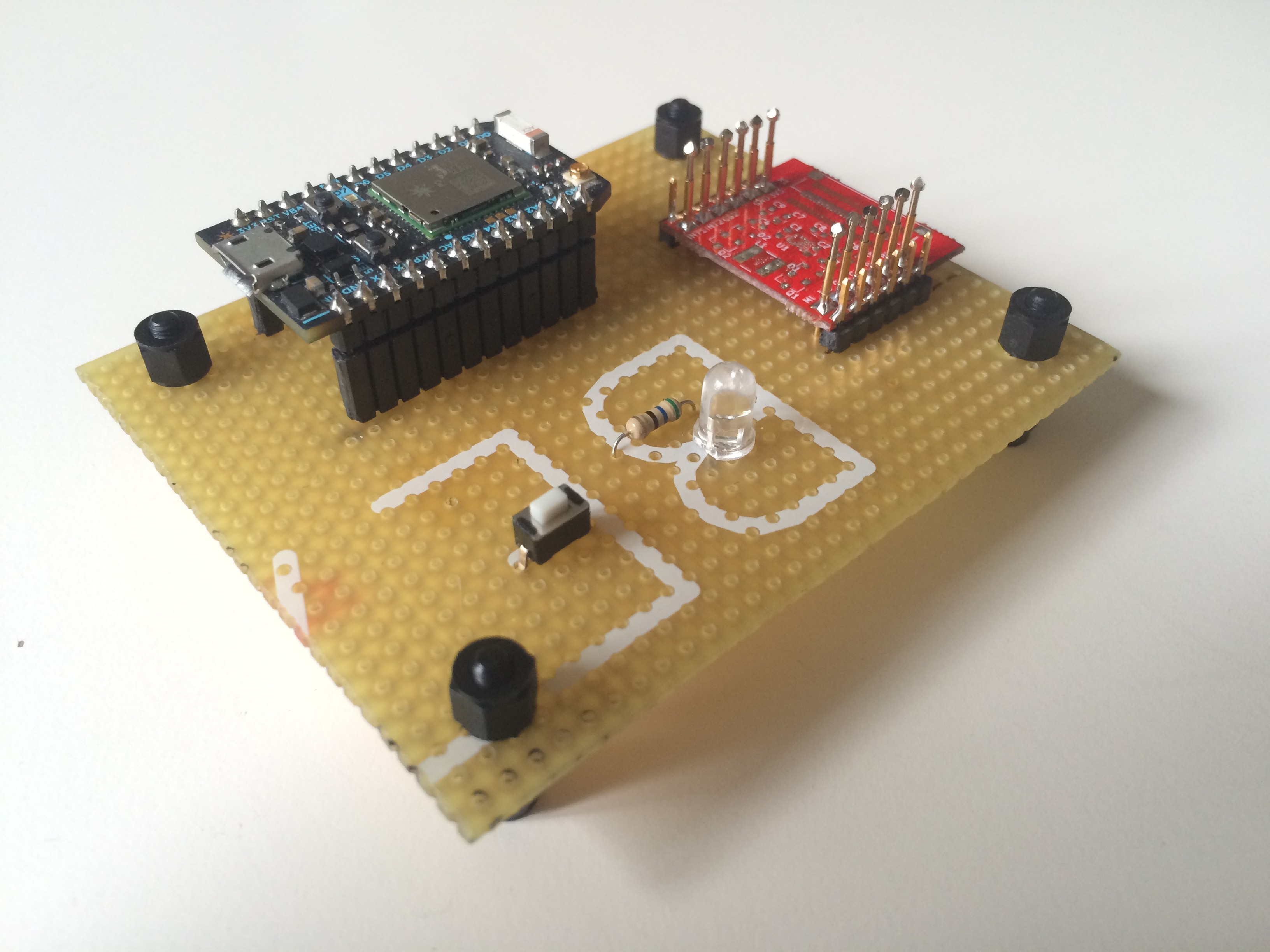
    To test the assembled drive modules we need a solderless testing jig. To save time and money on PCB design and manufacturing we decided to whip out some Perfboard and doing it quick and dirty.

    We ordered some pogo pins on eBay, checked our component drawer and fired up the soldering iron. The schematics can be found in our hardware repo.

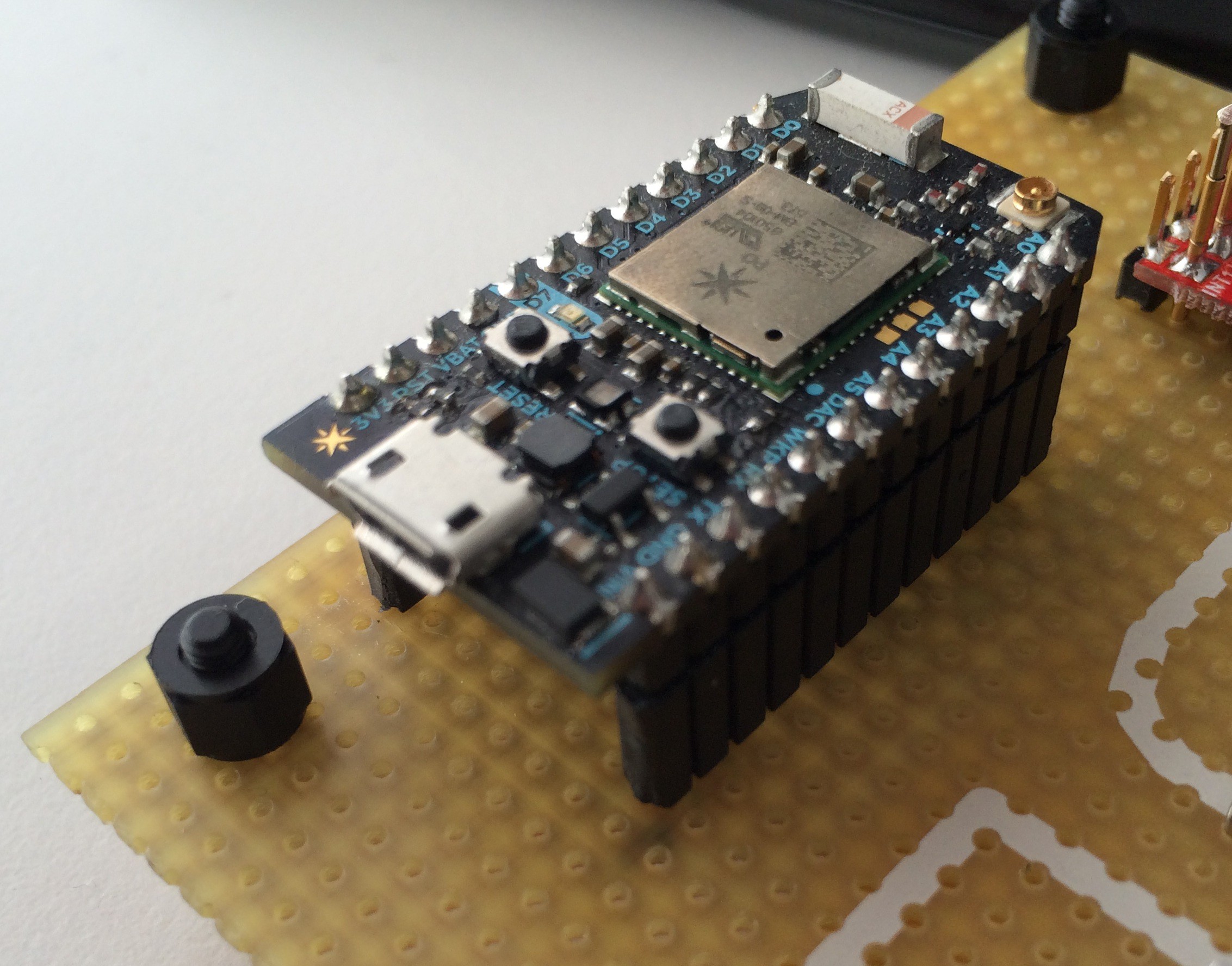
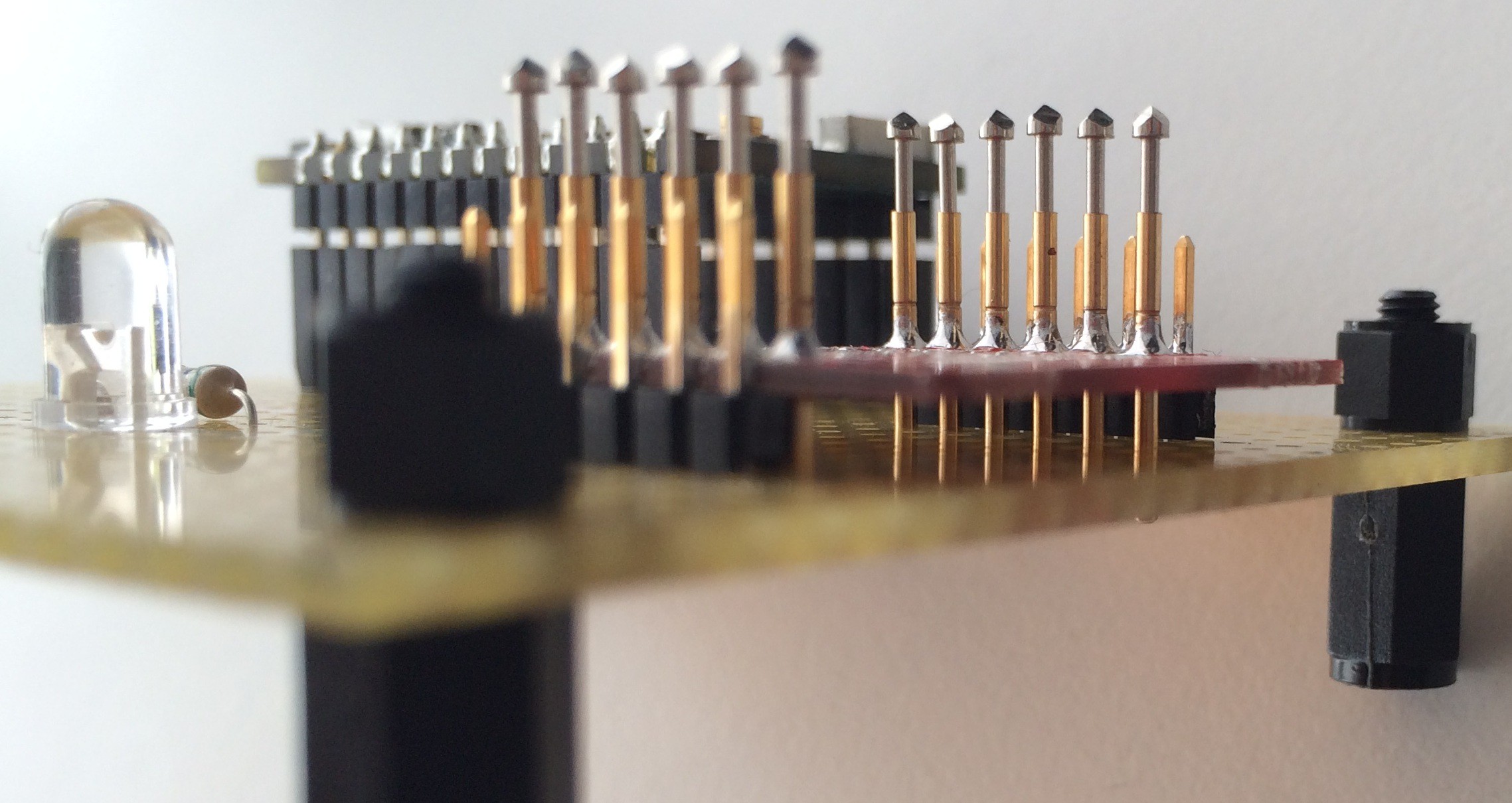
    Let's take a look at the result:

    We use a Particle Photon to drive the test program.

    To step through the program we use a pushbutton and we use a LED for feedback. The simplest IO interface there is.

    We use one of our Paperino module PCBs as a guide to make sure the pogo pins are straight(ish).

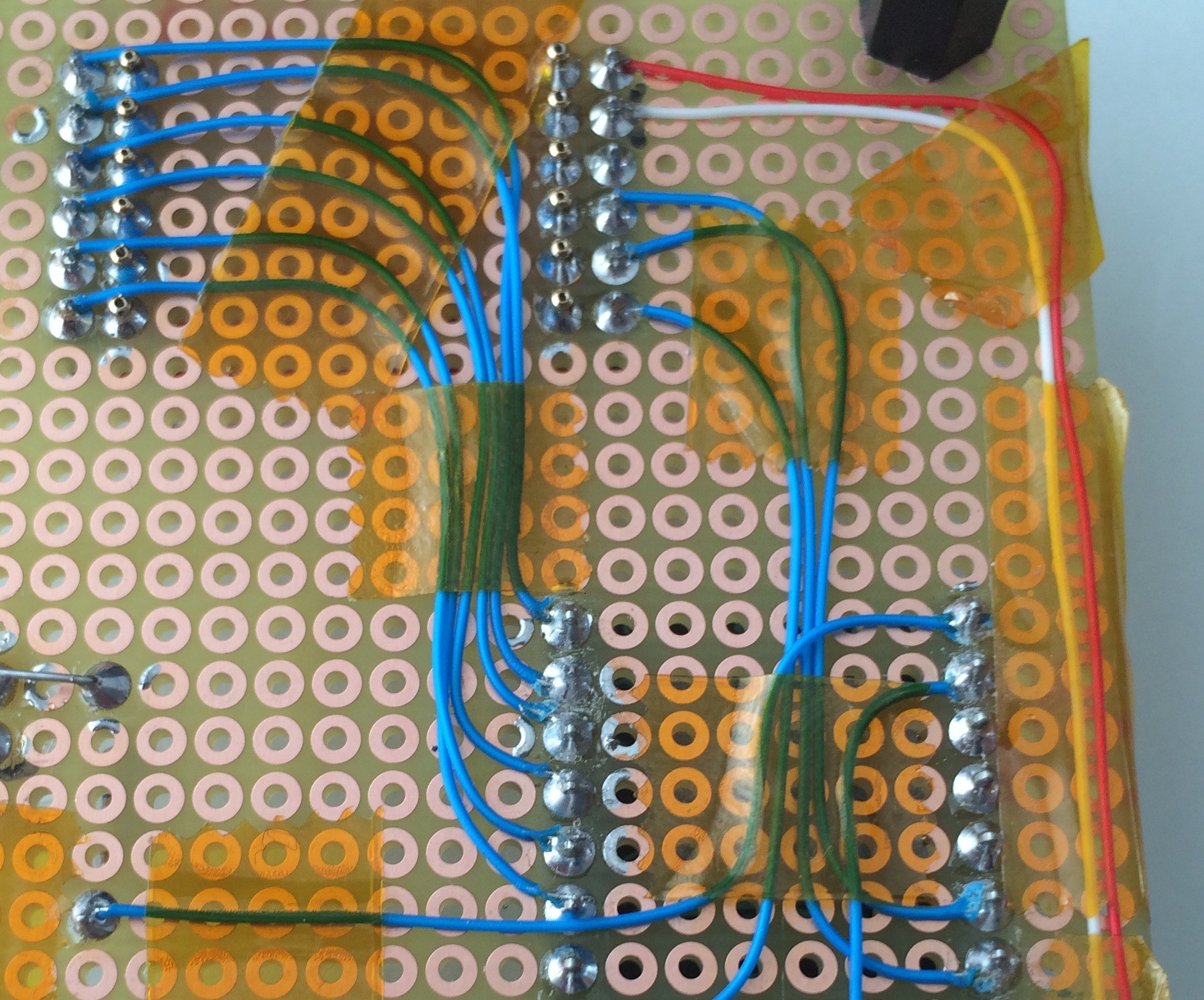
    Then we connect everything using wire wrap wire and some kapton to hold it in place (we didn't clean the solder joints, because we like to play hard and loose with our test jigs).

    Here's what the result looks like:

    Now all we have to do is wait for the module's pilot run PCBs to show up, assemble them and get some testing done.

View all 10 project logs

Enjoy this project?

Share

Discussions

Similar Projects

Does this project spark your interest?

Become a member to follow this project and never miss any updates