Close
0%
0%

Video Button SAO

Building a SAO with off-the-shelf parts and hot glue

Similar projects worth following
Taking a tiny WaveShare display with built-in RP2040 and turning it into a Simple Add-On

Background

When I heard about Hackaday Supercon 8's emphasis on Simple Add-Ons, I decided to wanted to turn my badge hack from 2023 into something I could mount on this year's badge.

Lots of people had noticed that the core hardware in the 2023 VectorScope badge was similar to a board that WaveShare sells, and I'd bought a few of those after the con to port my code onto.  They work well, but I ended up breaking both of the screens due to ill-advised 3D printed cases that fit too snugly.

The Button Display

Earlier this summer, I noticed that WaveShare had a new model with an even smaller 0.99" screen that came in a CNC-milled case.  I picked up a few from AliExpress to evaluate, and was able to get my code working with the new display fairly easily.  The biggest changes were the smaller resolution (going from 240x240 to 128x128) and handling a reversed vertical line update order.

I was also fortunate that the unit came with a breakout cable for the side connector, so I didn't need to source my own SH1.0 connector, I could just reuse that hardware.

Connecting it to the Badge

I'd originally wanted to make my own PCB, but while looking at other hardware, I found that AdaFruit stocks a AVR ISP connector on a breakout board for under $1 that exactly matches the addon-side of the SAO standard.  The pin labels aren't the same, but once you wire it up, who's looking at the board anymore?

With some diving into the schematic of the Waveshare module and the SAO standard, I made this diagram.
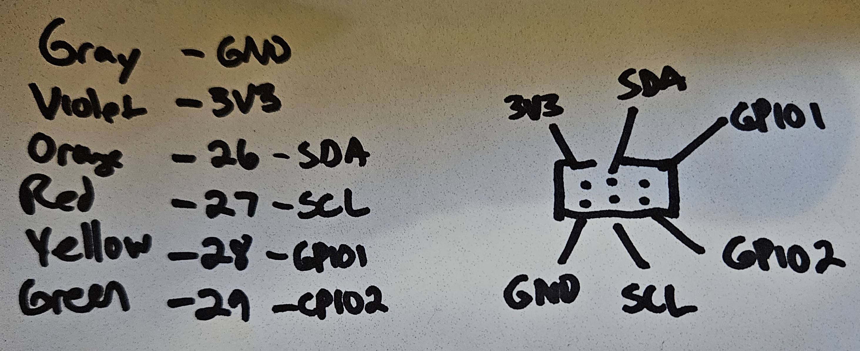
For use just as a display, you only need to hook up power and ground, but the WaveShare badge also includes an accelerometer and gyroscope IMU sensor that would be useful to expose via I2C to the host badge.

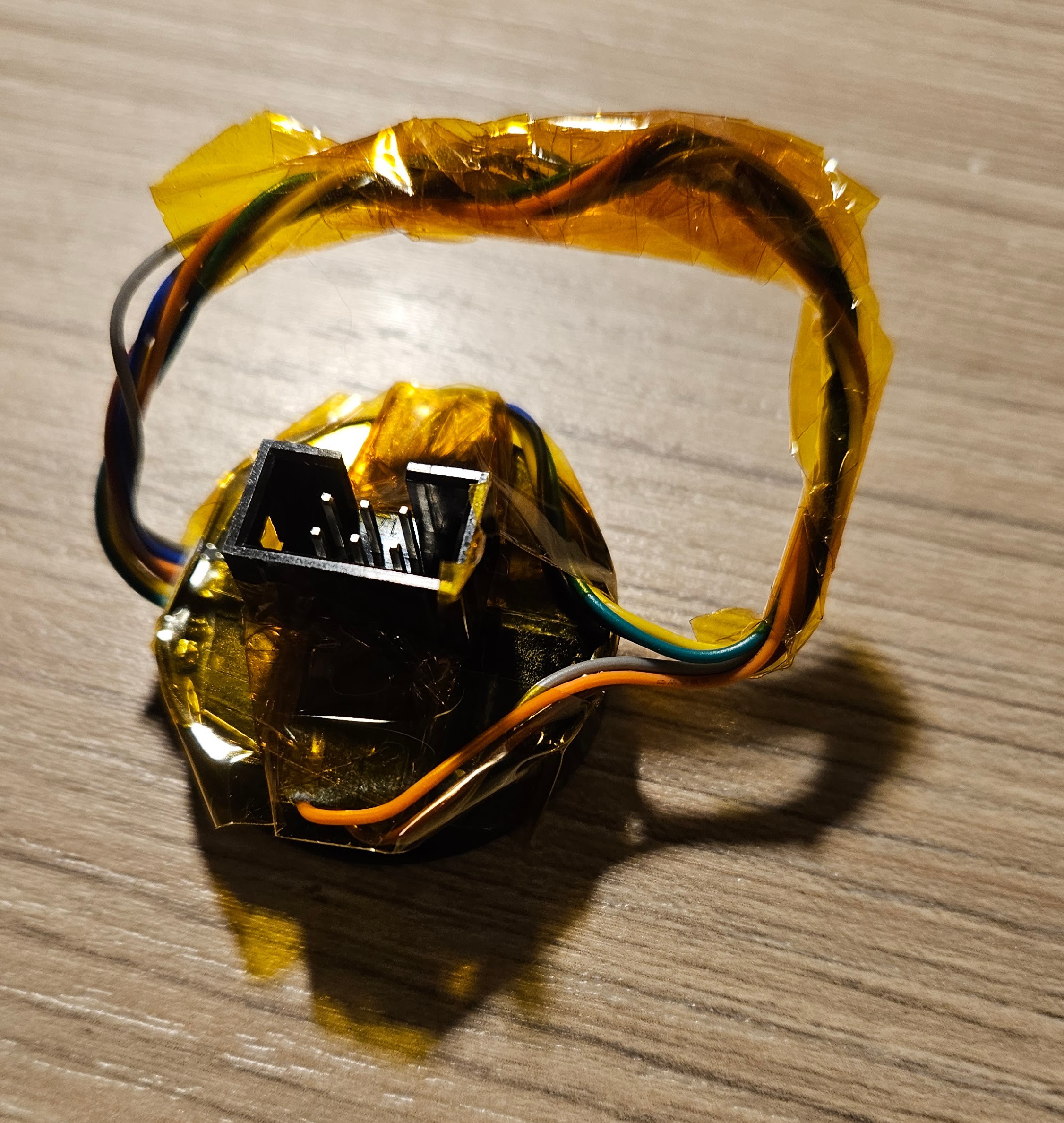
Physically, I measured the distance from the connector on the module to the pin holes on the AdaFruit board, added a little slack for wire stripping and user error, and cut the breakout cable.  After stripping the cable wires, I started soldering them into the holes, with a test after attaching GND and 3V3 to see if it would start.  That test was very fortunate, as it showed I'd connected to the wrong end, but that was fixed with minimal fuss.  After attaching the rest of the wires and another test, I used some hot glue to attach the board to the module and to fix the connection wires to the side of the plastic shield.  It's not the prettiest connection, but as I posted in the Supercon discord, I'm putting the "S" in SAO.

Power Problems

When I first tried this connected to the 2023 VectorScope badge, I could see a backlight activate on the display module, but the video player didn't start up.  Checking the SAO port on the badge showed that it only was supplying 3V, not the 3.3V from the spec.  It turns out that the SAO ports on the Supercon badges usually are connected to the AA battery directly, so you get whatever voltage is available from the cells.

The VectorScope badge does have a boost converter that produces 3.3V, and that's exposed on the connectors used to provide analog inputs for the vector display.  I tried wiring to that, and saw some execution, but it crashes early before showing a full frame.

At this time, I was resigned to having this not work as a SAO, but once I got a working variable power supply, I took a look at the actual operating range.  For my code as-is, I couldn't run below 3.1V and 60mA of current.

However, after doing these tests, I remembered that I'd setup my project to run the Pico in a 2.15x overclock (270Mhz) in order to get a higher frame rate.  With the smaller display, I could reduce the CPU speed back to the normal 125Mhz.  On testing, this didn't playback at 30fps, but was still acceptable around 24fps, and this worked at 2.95V and 40mA, which meant that it booted and played video connected to both my VectorScope and Voya4 badges!

Connectivity Problems

In looking at I2C connectivity, I found that the IMU...

Read more »

  • Slide Deck

    Ben Combee11/03/2024 at 18:12 0 comments

    I wrote up some slides this morning for a lightning talk, but it looks like I"m in the overflow list, so probably won't present.  The link for you to browse them is https://slides.com/unwiredben/tinyplayer

  • Specimen #2

    Ben Combee11/03/2024 at 03:26 0 comments

    I decided my Supercon 8 badge was a bit unbalanced, so I made a second specimen of the Video Button tonight.  This one is a little more temporary and was done entirely with kapton tape.

    I first applied a layer of tape to the back of the Waveshare unit, then took the cable from the Waveshare box and fit the pin connectors onto the bottom pins of a surface mount 2x3 header.  This is what you normally solder to the board, but they also were just the right size to fit over the breakout connectors.

    This is when I discovered that the wiring of the cables isn't consistent from module to module.  The order is the same, but the colors of wire used vary.  After fitting all the wires to the connector, I used ample tape to wrap the set of three wires, then to connect those header assemblies to the display module.  I also previously twisted the wires to make a more compact bundle between the display connector and the SAO connector, and used more tape to wrap that bundle.

    This time, I programmed the display with a name tag animation of the Combee Pokemon zooming with my name and handle floating above.  This was only a 20 second video, so it converted quickly and didn't take up much space.

    I also learned that the small screwdriver included with the kit isn't just for removing the back screws.  It's also the perfect size to insert to press the "boot" button on the side. No more breaking mechanical pencil leads for me.

    Having done a couple of these, I think I'm ready to make a small PCB that can take the place of the back of the case.  The trick will be finding internal points on the display PCB to connect to to get the signals.  I suppose you could desolder the side connector, but I'd rather not be destructive.

  • Fixed the color space and speed issues

    Ben Combee11/02/2024 at 05:44 0 comments

    I just committed a few changes to the GitHub repo for this project.  I made four significant changes tonight:

    1. I updated the video to a minute of the Roku City screensaver which seemed more appropriate for something that would mainly be playing over and over on my badge.
    2. I looked for a better MPEG-1 encoder than ffmpeg, and found old forum posts pointing to a Japanese tool called TMPEnc.  This has grown up into a professional codec used by the broadcast and media authoring ecosystem, but the venerable videohelp website found a link to an old freeware version, https://www.videohelp.com/software/TMPGEnc, that worked on my Windows 10 laptop.  After some tweaking, I had a working file at a lower bitrate which looked just as good as my ffmpeg encoded version.
    3. I figured out the color issue and it was a wrongly configured display driver.  When I originally tried to find a match for the GC9107 display driver, I was led astray by a forum posting saying that it was the same as the ST7789.  There's a lot of similarities, but the better match was the GC9A01, and once I changed that, I had the colors showing correctly.
    4.  I made the display code faster by running it on the second core in the RP2040.  This means I can overlay decoding and shifting out to the display.  I'd never used the second core before, but it wasn't hard to figure out.  The Arduino core for the RP2040 will automatically run code on the second core if you give it setup1 and loop1 functions.  I had to come up with a simple synchronization method, and after a little debugging, it was working well.

View all 3 project logs

Enjoy this project?

Share

Discussions

Similar Projects

Does this project spark your interest?

Become a member to follow this project and never miss any updates