 Nick Sayer
-
11Step 11
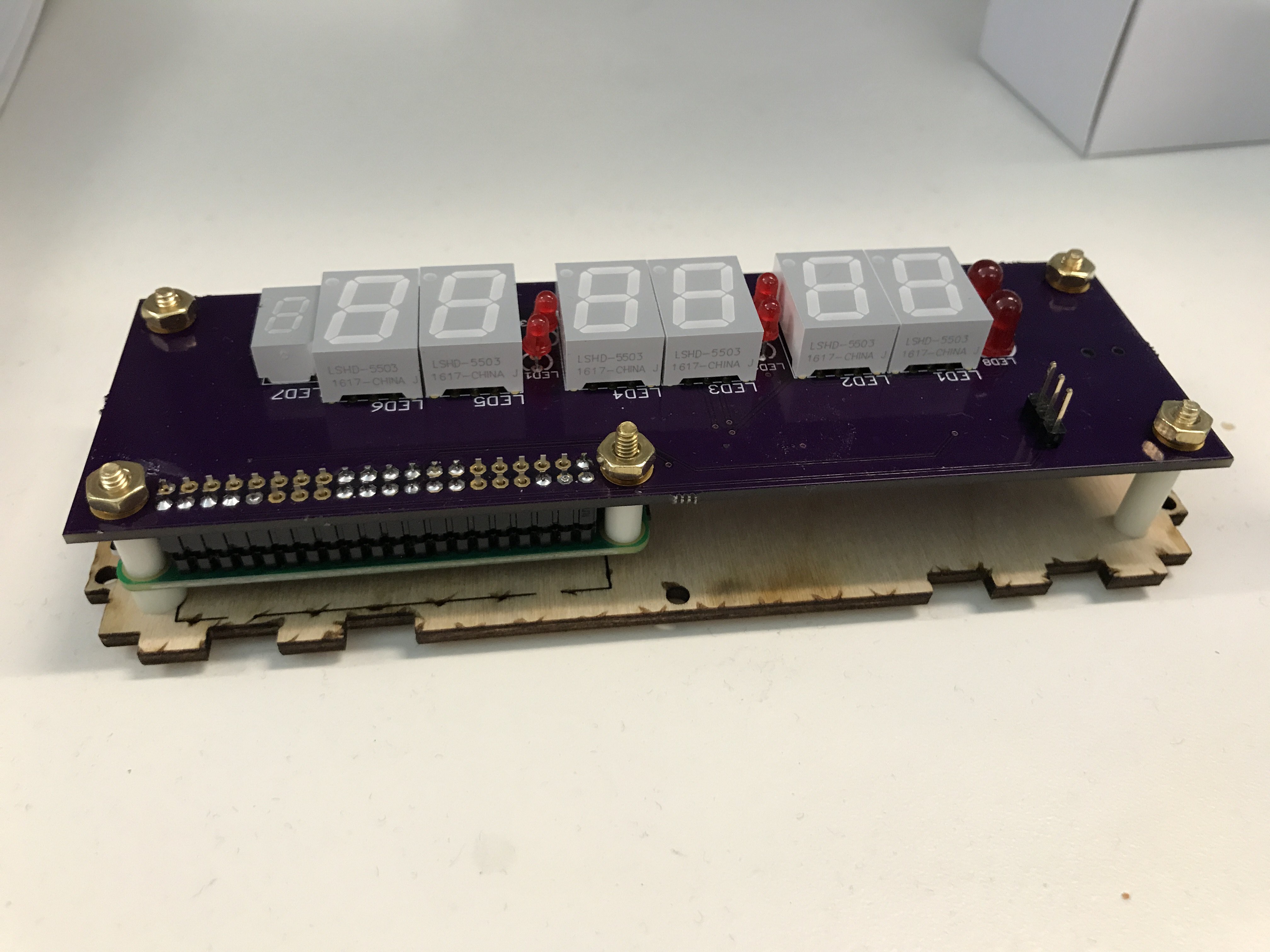
On the other side of the GPIO connector, place a 5/8" standoff between the boards and then lay the two boards on top of the 4 1" bolts threaded through the back panel of the case. The 1" bolt with the 3/16" standoff will go through the Pi Zero, the 3/8" standoff and the clock board. The remaining 1" bolts will go through the 5/8" standoffs and through the clock board. Add a lock washer and nut to each bolt and tighten.
![]()
-
12Step 12
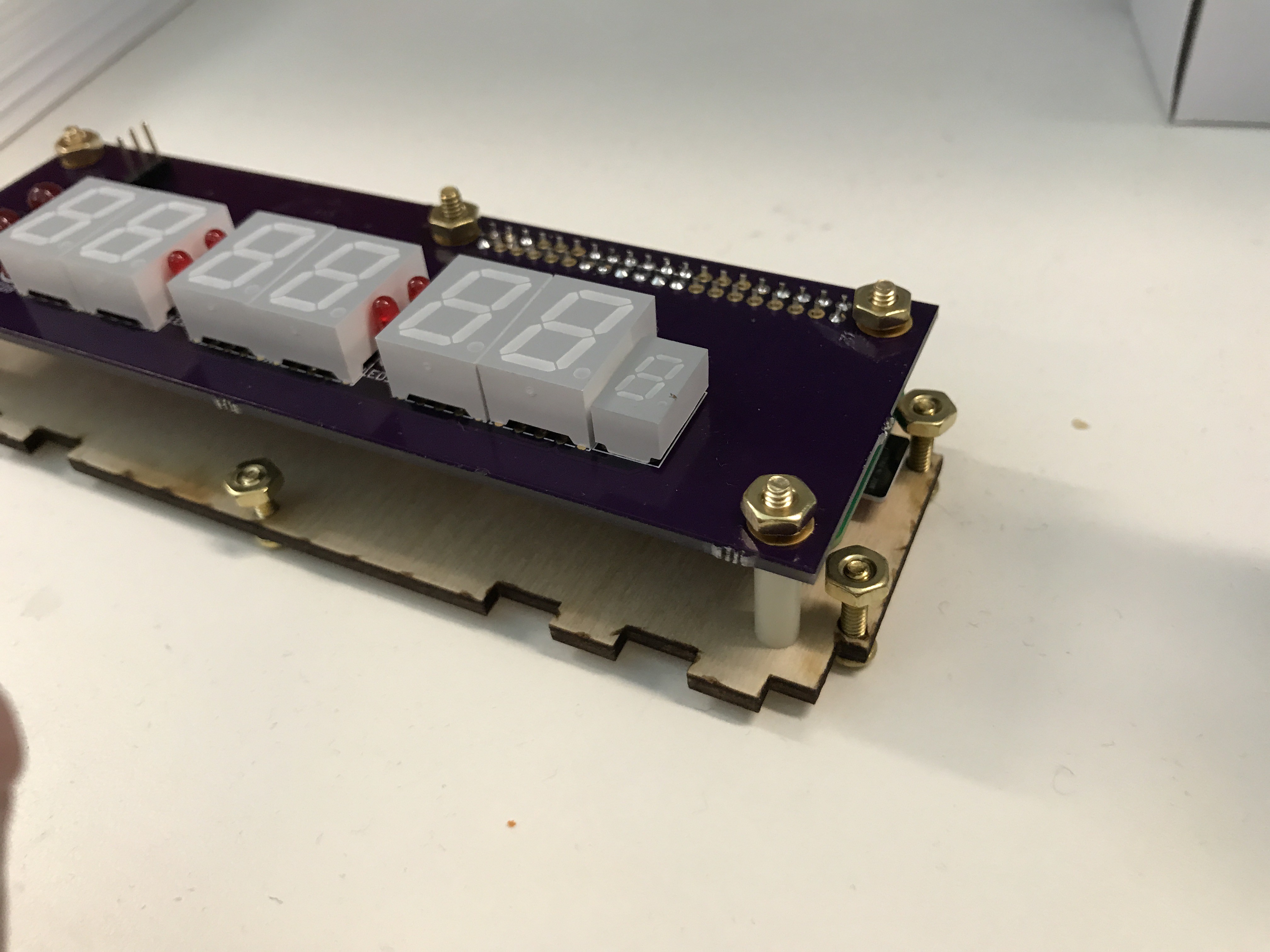
Thread the two 1/2" bolts through the back panel through the two holes on the short edge of the board adjacent to the pi. Loosely attach one nut to each, giving it only a couple of turns. On the remaining 4 holes of the back panel, similarly thread a 3/8" bolt from the bottom and loosely attach a nut.
![]()
-
13Step 13
Remove the paper from both sides of the acrylic. Insert the remaining 6 3/8" nuts through the holes in the acrylic from the front (the AM and PM etching is on the outside / front of the panel). Loosely attach the remaining 6 nuts to the bolts, again, giving them only a couple turns.
-
14Step 14
Attach the top and bottom panels loosely to the back panel. Take note of each end of the top and bottom panels: Each one has a notch on one side and a tab on the other. On each end of the clock, one of the two should have a notch and the other a tab. In other words, each should point the opposite direction.
Install the front panel (making careful note of the position of the AM and PM marks relative to the AM and PM LEDs on the clock board). Tighten the four screws holding the front, back, top and bottom panels together. -
15Step 15
Attach the left side panel to the left side. The left side panel is the one with the hole in it. The hole must line up with the power jack. If it doesn't, flip it top-to-bottom. If when you do so the tab and notch don't line up with the top and bottom panel, flip it front-to-back. Attach it to the front and back panel with the four bolts.
Attach the right side panel to the right side. Note that two of the notches for the nut/bolt attachment are longer. The longer ones mate with the 1/2" bolts extending from the back panel. Again, flip the panel until it lines up with the other case parts. Attach it with the bolts from the front and back panel.Your clock is complete.
Raspberry Pi Zero W desk clock
An LED desk clock driven by NTP on a Pi Zero W
Discussions
Become a Hackaday.io Member
Create an account to leave a comment. Already have an account? Log In.