 Nick Sayer
-
1Step 1
Build the board
The board doesn't have any particular special instructions for building it. All of the display modules and LEDs mount on the opposite side of the board from the surface mount components. When mounting the LEDs (AM/PM and the colons), all of the anodes should be in the bottom holes and the cathodes in the top. The colon LEDs should be mounted slightly up from the board so that their tops are more or less flush with the tops of the display modules.
Mount a low profile 2x20 .1" DIP socket set on the component side (opposite side from the display) for the Pi GPIO header.
-
2Step 2
Physical setup for the Pi
Mount a 2x20 .1" DIP header on the BOTTOM of your Pi Zero. For great justice, consider using a "double male" stacking header like this one (the benefit to that is you'll be able to connect other things on the top side of your Pi). You will plug that header into the sockets on the clock board. The component side of the Pi will face upwards.
Before mounting the Pi on the clock board, thread a 3/4" 4-40 machine screw through the two holes adjacent to the header from the display side. On the component side, add a 3/8" spacer, then add the Pi on top. Firmly mate the header pins into the sockets. Add a lock washer and nut to the screws and tighten firmly, but not too tight.
-
3Step 3
Power test
Apply power to the 2.1mm jack on the clock board. You should see some signs of activity from the green LED on the Pi. You won't see the LED display do anything at all - by default the controller chip boots up in sleep mode.
-
4Step 4
PiBakery setup
Download PiBakery. In the GitHub repository there's a PiBakery recipe XML file. Import that into PiBakery and modify the WiFi setup to match your local configuration. Optionally, you can make other changes (it's strongly recommended that you add something to change the default pi user password so that the default one is never present on the network). Write this configuration out to an SD card. Insert that card into your Pi and boot. The Pi will reboot once and the clock should start and show the correct time.
-
5Step 5
Alternative manual software setup
If you don't want to use the PiBakery instructions above, or wish to have more manual control over the process, this set of instructions should do the equivalent to the above.
Take an 8 GB microSD card and install the latest distribution of Raspbian Jessie Lite on it. If you're using a Pi Zero W (or a Pi 3) and want to use the serial console, before you remove the card mount the FAT filesystem and edit config.txt to add somewhere near the end:
enable_uart=1
Insert that card into the Pi. Connect a TTL serial port up to the console 3 pin header on the clock board. If you're using other than a Pi Zero W (or if you want to use other than WiFi), connect some sort of networking hardware - either Ethernet or WiFi - to the USB OTG port. Start up a terminal emulator on your serial port and set it up for 115200 baud 8N1. Apply power to the clock board.As an alternative to the serial console, you could instead connect a USB keyboard to the USB OTG port and an HDMI monitor to the mini HDMI port. The instructions that follow work the same either way.
Your serial console should show the boot process. When the login prompt appears, the default credentials are "pi" and "raspberry". Log in and run
sudo raspi-config
Go into the various menus and perform these tasks:
- Set the WiFi regulatory domain
- Set the timezone
- Set the locale
- Turn on SSH
- Enable SPI
- Change the password for the 'pi' user
- Change the hostname (if desired)
- Expand the filesystem
- Exit and reboot
When the pi comes back up, if you're going to use Ethernet, then your Pi should be on the network and reachable. If you're going to use WiFi, you'll need to log in on the console again and edit /etc/wpa_supplicant/wpa_supplicant.conf. Add a "network" block suitable to describe your wifi network:
network={
	ssid="[network name]"
	key_mgmt=WPA-PSK
	psk="[network password]"
}
Reboot again for that to take effect.Once your Pi is reachable on the network, confirm that you can log in remotely and sudo to root. At that point you can disconnect the serial console.
-
6Step 6
Finish software setup
With your Pi on the network, you should be able to use
ntpq -pn
to check that NTP is finding peers to use and successfully setting the time.
At this point it's a good idea to use apt-get to update and upgrade your machine to the latest code.
At this point you can fetch the SPI_Clock.c code from the GitHub repository. Compile it with
gcc -O -std=c99 -o spi_clock SPI_Clock.c -lrt
sudo mv spi_clock /usr/bin
Test spi_clock by running it as root:
sudo /usr/bin/spi_clock -d
When it starts, you should see it test all of the LED segments for one second, and then start displaying the time. You can use control-C to stop it once you've verified that it's working. If you run 'spi_clock -h', you'll get usage. You can try out various command line arguments with -d to run the clock in the foreground and control-C to stop it.
Lastly, edit /etc/rc.local and add a line to the end to launch spi_clock with whatever options you desire, this time leaving off the -d.
-
7Step 7
If you wish, you can run spi_clock as other than root. For this to work, you need to grant permission to whatever user you wish to use the real-time scheduler and lock memory. Add these lines to /etc/security/limits.conf:
*		-	rtprio		100
*		-	memlock		16384
These lines will allow any user to set any realtime priority they like and lock up to 16M of RAM. You can change the "*" to a specific user if you wish.
-
8Step 8
Building the enclosure
If you're going to use the GPIO header on the Pi, then use a small saw and cut the tabs holding the knock-out in place over the header. Be careful near the edge of the wood where it's quite narrow.
If you're going to use the HDMI or USB connectors on the Pi, then the best suggestion is to use right-angle extenders and leave off the bottom panel of the case.
The enclosure comes with a smoked acrylic front panel and wooden back, side, top and bottom panels. The hardware bag includes:
- 4 1" brass 4-40 bolts
- 1 3/4" brass 4-40 bolt
- 2 1/2" brass 4-40 bolts
- 10 3/8" brass 4-40 bolts
- 17 brass 4-40 nuts
- 5 4-40 lockwashers
- 3 5/8" standoffs
- 1 3/16" standoff
- 2 3/8" standoffs
-
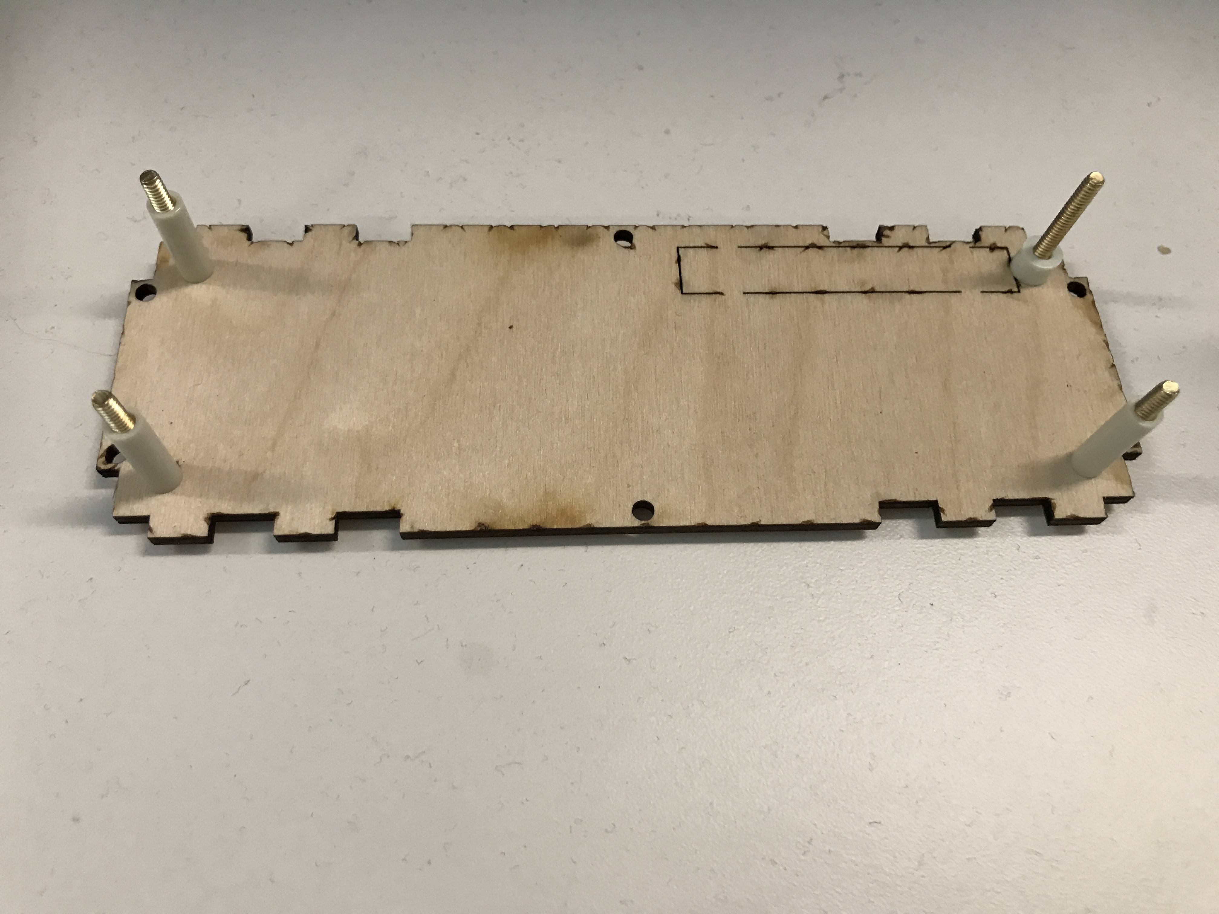
9Step 9
Place the back panel writing-side down on a flat surface. Thread the 4 1" bolts through the corners from the bottom (the outside of the finished case). On the bolt nearest the GPIO header cut-out, place the 3/16" standoff and on the other four, place a 5/8" standoff.
![]()
-
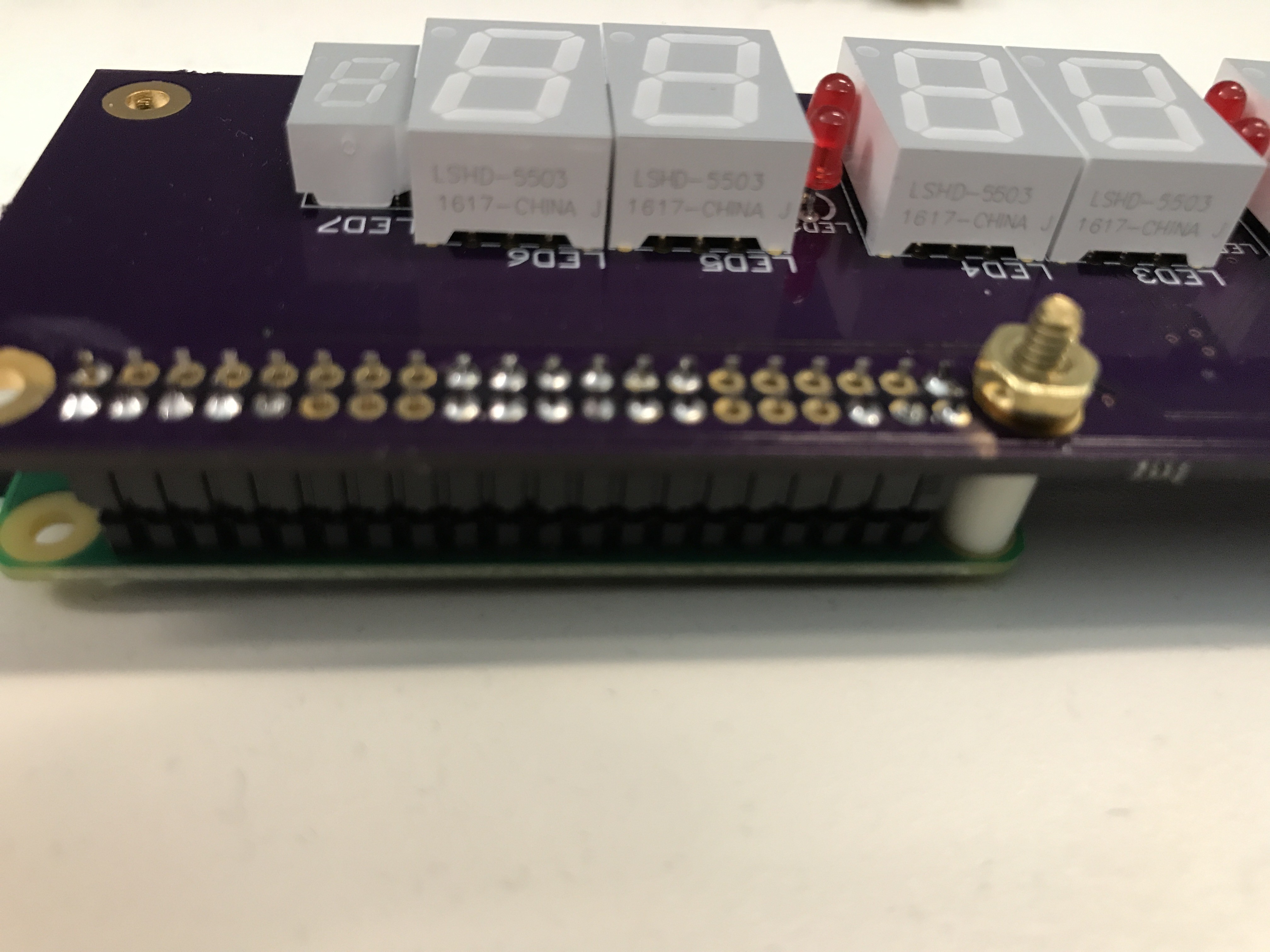
10Step 10
Connect the Pi Zero to the clock board, spacing the two boards 3/8" apart. On the side of the GPIO header away from the edge of the board (the side with the camera connector), place a 3/8" standoff between the two boards. Thread the 3/4" bolt through the two boards starting with the Pi Zero. The bolt head should rest on the Pi Zero and the threaded end of the bolt should come through the display side of the clock board. Place a lock washer on the bolt and thread a nut on and tighten.
![]()
Raspberry Pi Zero W desk clock
An LED desk clock driven by NTP on a Pi Zero W
Discussions
Become a Hackaday.io Member
Create an account to leave a comment. Already have an account? Log In.