Close
0%
0%

Geocache Puzzlebox

Lead the player through a set of preset coordinates where a puzzle unlocks the your next destination

Similar projects worth following
Credit where credit's due: Inspiration and starting place for this project was Sean Hodgins' excellent Arduino Geocache Locator (link below).

Project was for the bucks night of a very close friend. The idea was a device that could facilitate a walking puzzle crawl in Sydney. A neopixel ring and a GPS module create a compass, leading you to a location (a pub in our case). At each location a puzzle would need to be solved which would result in a binary code. Entering the code into the device gives you a new location and sends you on your way. It was a great night.

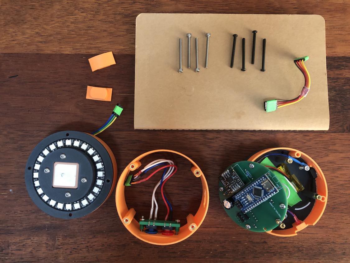
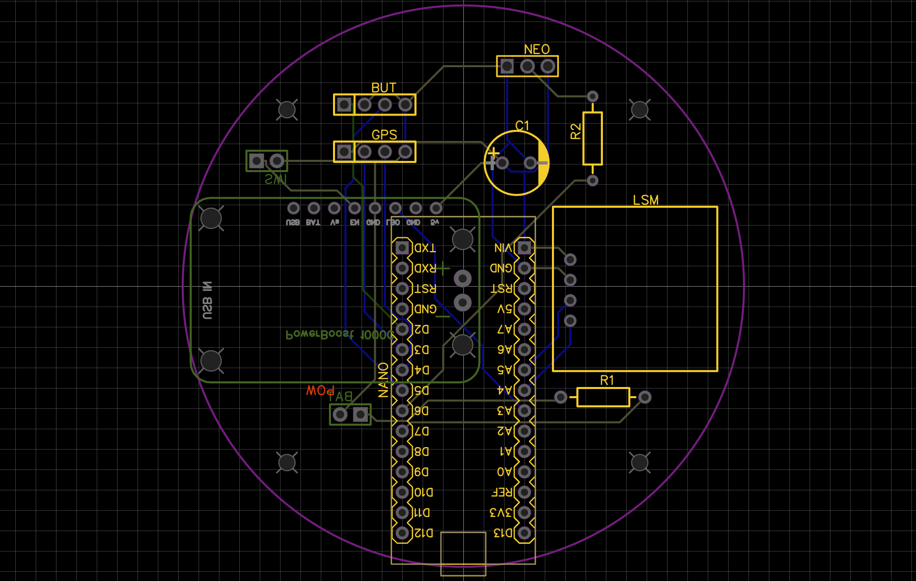
The project was printed on a Bambu Labs X1C with a 0.4mm nozzle in PLA+ and PLA-CF. It probably can print in just about anything. Files can be exported or remixed from Tinkercad.

Credit to Scott and Balázs for letting me hijack your bucks with this baffling ordeal! I hope in time everyone will forgive me.


Gerber_geocache_puzzlebox_NEW_PCB_2024-11-26.zip

Gerber files for the PCB if you want to print your own

x-zip-compressed - 20.09 kB - 11/26/2024 at 08:26

Download

View all 17 components

  • About the project

    davejharmon11/26/2024 at 09:16 0 comments

    Background

    I began this project back in 2022 and have been tinkering with it on and off for the last couple of years. It was a great test of my skills as a beginner hobbyist - I’ve had to improve my skills at 3D enclosure design, PCB design, coding and soldering along the way. I think its a fun build, but I may have rose-coloured glasses due to the time I’ve sunk into it. Your mileage may vary!

    As I said in the description, I originally intended to simply recreate Sean Hodgins’ very cool Arduino Geocache Locator but found myself iterating on it as I tinkered. I really liked the idea of a physical object that is child-safe, easy to program and able to lead people through a series of checkpoints using only a physical LED display. When I realised I could use it for my friend Scott’s bucks party it gave me the deadline I needed to get it finished.

    One more thing: this is the first project of this type I’ve completed since our daughter Frankie was born! It felt real good to be able to set my mind to an outside-work-and-family-hours goal and still have the energy to pull it off. There were some late nights!

    The Goal

    I had some starting goals in mind:

    1. Create a puzzlebox to lead us through a series of pubs in the inner west of Sydney.
    2. At each pub we would create a small puzzle to be solved by the group while we had some drinks.
    3. Each puzzle’s answer would be some kind of binary 8-digit sequence (ie. 10101100). Entering the sequence into the puzzlebox would unlock a new location to visit.
    4. Rinse and repeat!

    To Operate

    1. Turn the puzzlebox on using the switch at the base. The LED ring will show a blue animation pattern until it gets a GPS lock where it will turn to gold.
    2. Once you have a GPS lock, hold down both buttons for 2 seconds to enter the password mode. The red LED turns on to tell you when both buttons are down as a visual clue something is happening*.
    3. When you have entered password mode a timer begins to count down on the NeoPixel ring. While it is still playing out you can enter an 8-digit binary sequence by pressing the blue and red buttons. If the sequence is correct a target is located and the compass begins to navigate. If the sequence is incorrect, or you run out of time, the gold cycle returns.
    4. While in navigation mode, the LEDs closest to your destination light up in the colour associated with your target. As you get closer, more LEDs illuminate. When you are standing at your target, all the LEDs will be illuminated.

    All of this is a bit intentionally complex - its a puzzlebox! To make it more confusing I didn’t explain how to operate it, but instead packaged it with some baffling ikea-style instructions:

    * - This LED was originally meant to be a battery indicator, but I forgot to test my circuit before printing the PCB and wired it very wrong. Luckily I’d set it to a data pin, so was able to find a use for it.

    The Code

    Seemed simple and I was trying to keep the ambition of the project from blowing out too much. Already I knew this would push me a bit. Originally I planned to reuse Sean’s code but soon realised I’d need my own. As I’m a beginner and got turned around a lot, I ended up restarting the project four times from scratch as I realised I no longer understood my code or could get it to do what I wanted. The final code on github is very, perhaps pedantically, broken down into parts - and I’m sure there’s still a lot of inconsistencies in how I laid it out! It includes:

    1. Individual handler files for the
      1. buttons
      2. compass module
      3. GPS module
      4. NeoPixel ring
    2. Const files for the constants and the coordinates.
    3. A main.cpp file to tie it all together.

    To adjust the puzzlebox’s codes and target locations, just adjust the GPS_Coordinates items in the locations[] array in GPS_Coordinates.cpp. The sample code is the bar crawl we took a couple of months ago - you’ll probably want to change them!

    Thank you for reading!

    This is my first hackaday.io project. If there’s...

    Read more »

View project log

  • 1
    Assembly

    To assemble, its easiest to start from the bottom and work your way up. The PCB is designed to hold most of the modules with the powerboost on the bottom facing the battery. The bottom plate has a hole to hold a single screw which I used to wedge the switch into position (a very lazy alternative to modelling a proper housing for it).

    The four pillars on the base plate require a 4mm threaded standoff to line up the Nano's USB-C port with the enclosure's opening. If you're using heat set inserts you can just add 4mm to the Tinkercad design.

    Don’t neglect the capacitor - I found otherwise the neopixel has a tendancy to crash the box due to power consumption if it draws too much power. If you don’t feel like printing the PCB here is the circuit and EasyEDA PCB design (and shoutout to nomstrosity for showing me how to use EasyEDA and designing v1 of my board for me!)

    35mm M3 bolts keep the project in place with heat set inserts in the middle ring holding everything together - which really constrained the space I had to play with. Its not too tight a fit, but good to do a dry fit. One issue I learned early on is to try not to remove the tiny u.FL connector on the GPS module too many times as it can break very easily - this is why the GPS module attaches to the lid.

    The plugs are just there to cover the access points for the Nano and the PowerBoost USB ports. When you do run the code make sure you don’t turn the GPS on until its outside and give it a good 10-15m to find itself the first time. It seems to take much less time subsequently but it cost me a day thinking I had a dodgy module!

View all instructions

Enjoy this project?

Share

Discussions

Similar Projects

Does this project spark your interest?

Become a member to follow this project and never miss any updates