JP Gleyzes
Background
My friend bought this wonderful engine from UMS_technologies
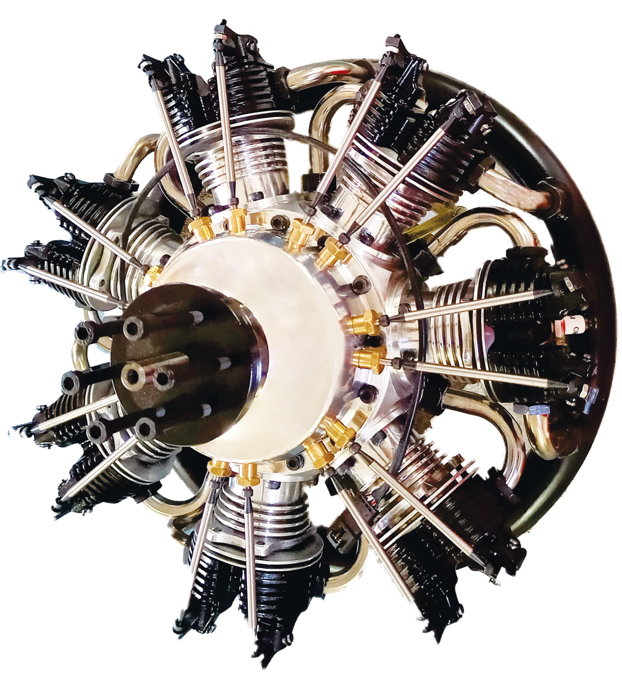
It's a 7 cylinders star engine which uses "glow fuel".
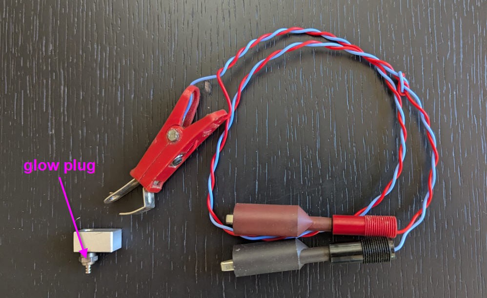
The fuel ignites when it comes in contact with the heating element of the glow plug. Between strokes of the engine, the wire remains hot, continuing to glow partly due to thermal inertia, but largely due to the catalytic combustion reaction of methanol remaining on the platinum filament. This keeps the filament hot, allowing it to ignite the next charge, thus sustaining the power cycle.
A 7 cylinders engine is thus equiped with seven glow plugs (one per cylinder)
To start the engine the glow plugs must be heated, then the motor starts, then the heaters can be removed.
In real life diffuclties may occur, the motor starts properly and keeps running at high speed. But when reducing the throttle, temperature at the heating element decreases and may not be sufficient to ignite to next charge... and one cylinder stops... Engine is still running but the rotation is less powerful, noisy and un balanced...
To prevent this behavior an idea would be to keep the heating elements switched on external battery (glowing).
This of course works, but the current into the glow plug is quite high (4A at 1.5V) so that the battery into the plane would be really big (and thus heavy)...
This project is an attempt to power the heating elements only when the engine is at low speed (low throttle).
I can't help showing you the result !
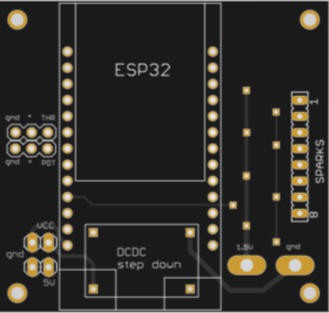
Electronics schematics (version 1)
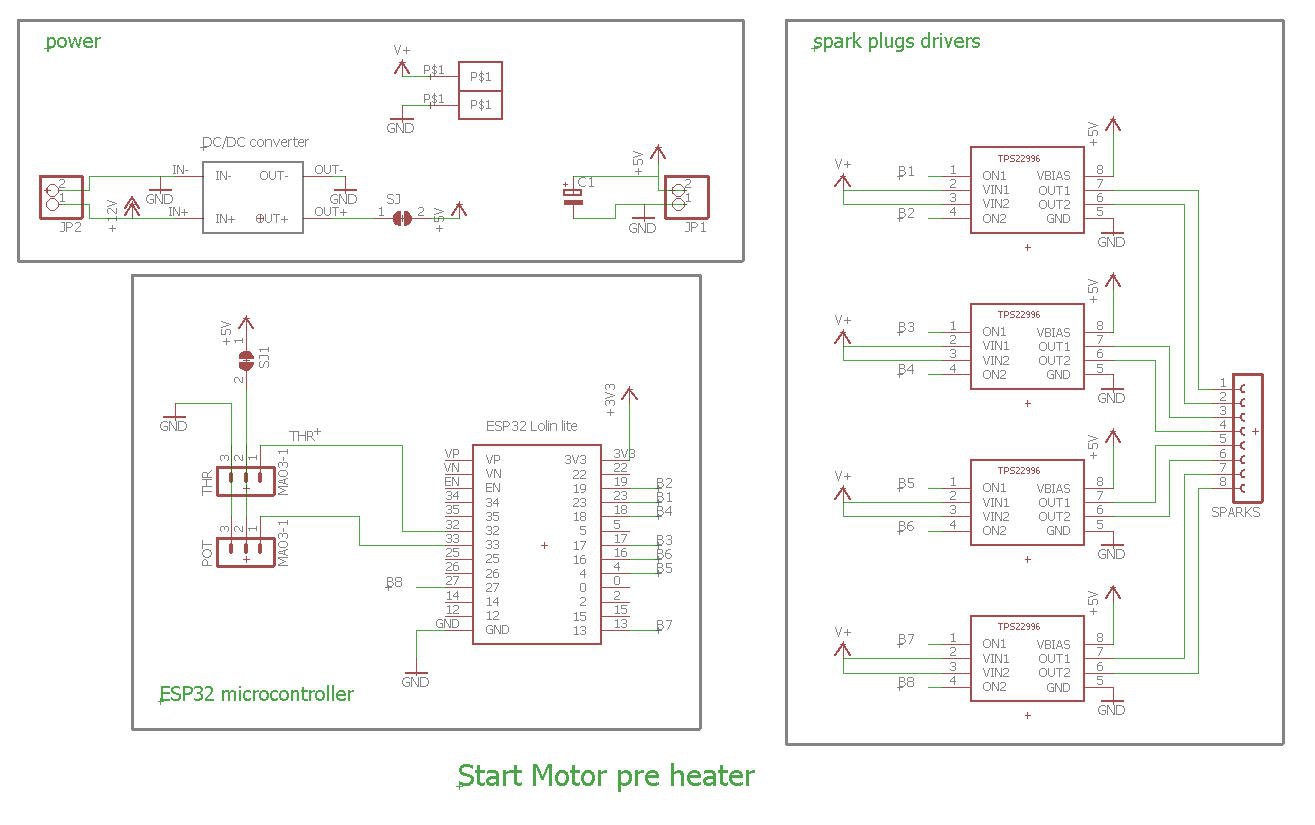
Schematics could not be more simple:
- an ESP32 will take care to read the throttle stick coming form the radio receiver and to drive the glow plugs drivers
- spark drivers are TP22996 Ti chips they are dual chanels load switches
- Number of channels 2
- Vin (min) 0.6V
- Vin (max) 5.5V
- Imax 4A
It was quite difficult to find a proper driver for this application as we needed both high current and low voltage (4A at 1.5V). This TP22996 seems to be perfect !
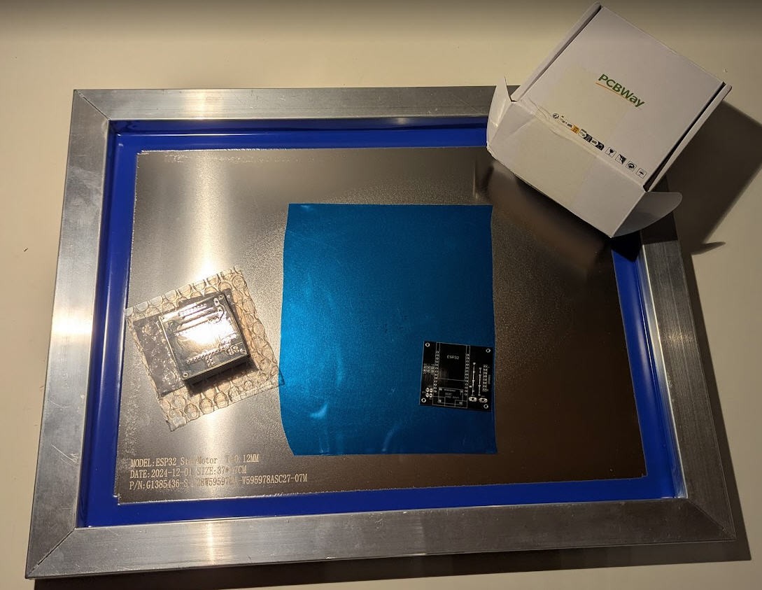
A PCB was kindly produced by PCBWay and proved to "kinda work". But finally it had enough drawbacks to change for a more conventionnal schematics.
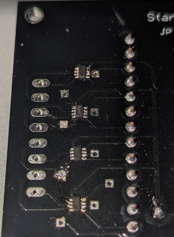
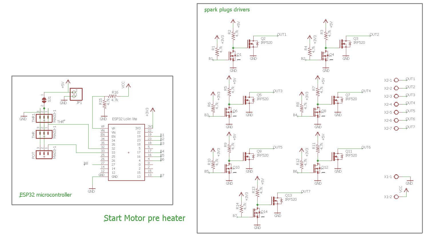
Schematics version 2
Compared to V1, several things have changed :
- power is now produced by a Li-Ion battery at 3.7V.
- dual stages N channels mosfets are used for each glow plug control. They are much easier to solder ! (one small 2N7002 and a logic level big one : FQP30N06L)
Powering glow plugs at more than 1.2V allows to avoid voltage drop and very big wires to drive the glow plugs.
However 3.7V is way to high to directly power the glow plugs. They would blow as an incandescent light...
So we need to control the voltage delivered to each glow plug with a PWM signal produced by the ESP2 and driven by the mosfets. Note that two resistors pull down the gates of the mosfets for each plug. So that , when power is applied, the glow plugs are switched off electrically. Then, after boot, the ESP32 can safely take again the control.
Note also that all the glow plugs share the motor body as the high side of the mosfets switches. The central electrod can only be controled by the low side of the switch.
This means that the body of the motor is not at the electrical ground but at the +3.7V.
This works safely if you take care not to connect anything else to the mass of the motor thinking that it is grounded... Take care !
Finally, to avoid to empty the Li-Ion battery (and to definitively kill it) I have added a voltage measurement to automatically (by software) stop the sparks when voltage is too low (let say under 3V).
Using protected 18650 battery would be another solution to avoid over discharge. Both solutions can safely co exist.
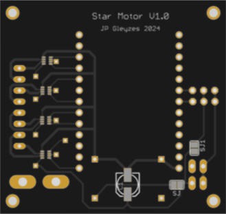
PCB version 2
I have designed a nice and compact PCB allowing to fit into an RC plane cockpit.
The PCB was again kindly sponsored by PCBWay and is as usual of excellent quality.

You can order it here: PCBWay shared project. It's cheap, delivered...
Read more »