 JP Gleyzes
Background
My friend bought this wonderful engine from UMS_technologies
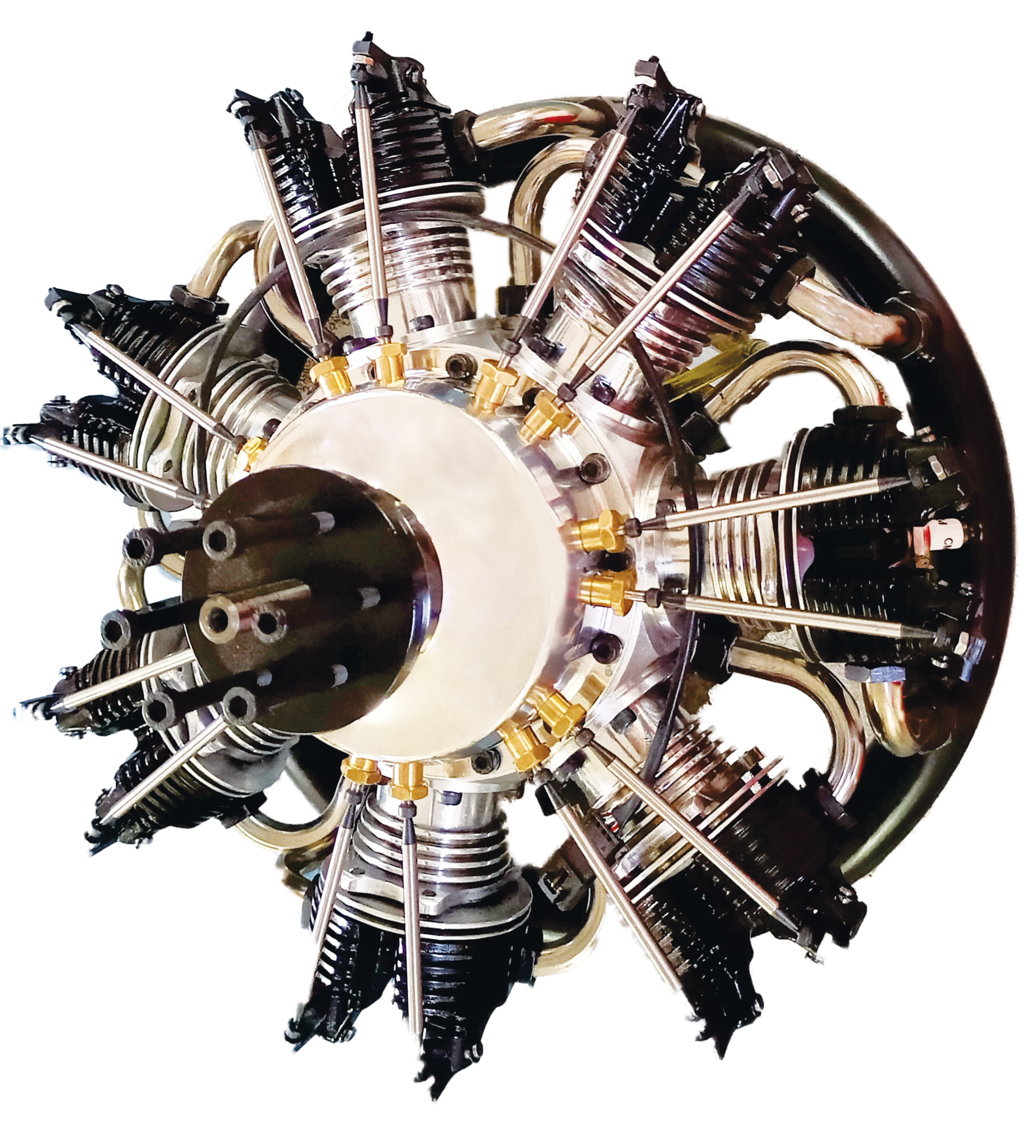
It's a 7 cylinders star engine which uses "glow fuel".
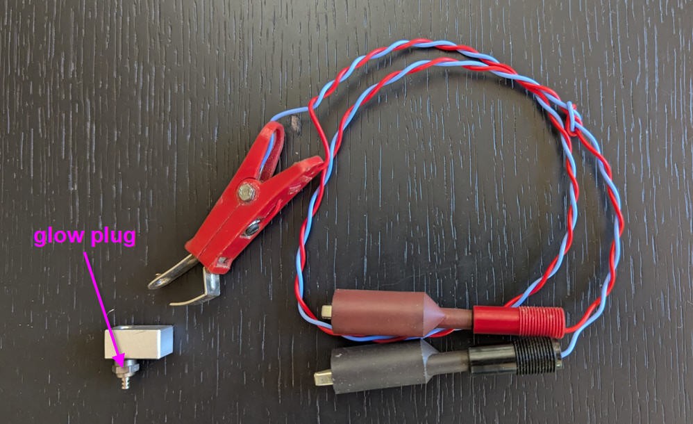
The fuel ignites when it comes in contact with the heating element of the glow plug. Between strokes of the engine, the wire remains hot, continuing to glow partly due to thermal inertia, but largely due to the catalytic combustion reaction of methanol remaining on the platinum filament. This keeps the filament hot, allowing it to ignite the next charge, thus sustaining the power cycle.
A 7 cylinders engine is thus equiped with seven glow plugs (one per cylinder)
To start the engine the glow plugs must be heated, then the motor starts, then the heaters can be removed.
In real life diffuclties may occur, the motor starts properly and keeps running at high speed. But when reducing the throttle, temperature at the heating element decreases and may not be sufficient to ignite to next charge... and one cylinder stops... Engine is still running but the rotation is less powerful, noisy and un balanced...
To prevent this behavior an idea would be to keep the heating elements switched on external battery (glowing).
This of course works, but the current into the glow plug is quite high (4A at 1.5V) so that the battery into the plane would be really big (and thus heavy)...
This project is an attempt to power the heating elements only when the engine is at low speed (low throttle).
I can't help showing you the result !
Electronics schematics (version 1)
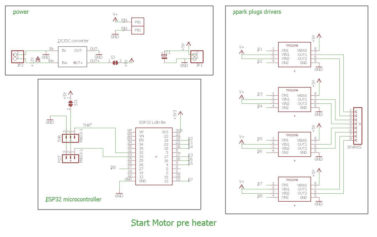
Schematics could not be more simple:
- an ESP32 will take care to read the throttle stick coming form the radio receiver and to drive the glow plugs drivers
- spark drivers are TP22996 Ti chips they are dual chanels load switches
- Number of channels 2
- Vin (min) 0.6V
- Vin (max) 5.5V
- Imax 4A
It was quite difficult to find a proper driver for this application as we needed both high current and low voltage (4A at 1.5V). This TP22996 seems to be perfect !
A PCB was kindly produced by PCBWay and proved to "kinda work". But finally it had enough drawbacks to change for a more conventionnal schematics.
Schematics version 2
Compared to V1, several things have changed :
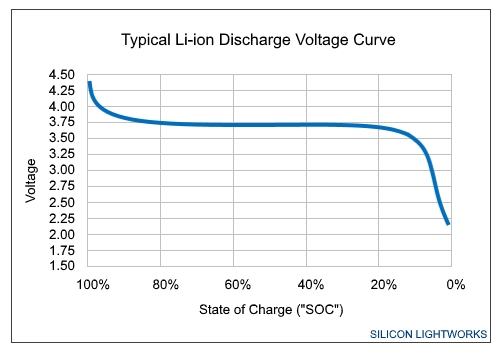
- power is now produced by a Li-Ion battery at 3.7V.
- dual stages N channels mosfets are used for each glow plug control. They are much easier to solder ! (one small 2N7002 and a logic level big one : FQP30N06L)
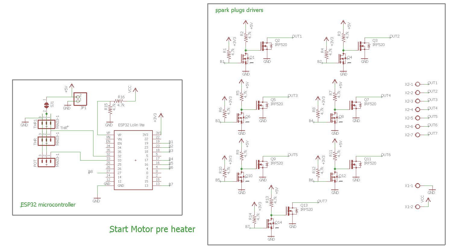
Powering glow plugs at more than 1.2V allows to avoid voltage drop and very big wires to drive the glow plugs.
However 3.7V is way to high to directly power the glow plugs. They would blow as an incandescent light...
So we need to control the voltage delivered to each glow plug with a PWM signal produced by the ESP2 and driven by the mosfets. Note that two resistors pull down the gates of the mosfets for each plug. So that , when power is applied, the glow plugs are switched off electrically. Then, after boot, the ESP32 can safely take again the control.
Note also that all the glow plugs share the motor body as the high side of the mosfets switches. The central electrod can only be controled by the low side of the switch.
This means that the body of the motor is not at the electrical ground but at the +3.7V.
This works safely if you take care not to connect anything else to the mass of the motor thinking that it is grounded... Take care !
Finally, to avoid to empty the Li-Ion battery (and to definitively kill it) I have added a voltage measurement to automatically (by software) stop the sparks when voltage is too low (let say under 3V).
Using protected 18650 battery would be another solution to avoid over discharge. Both solutions can safely co exist.
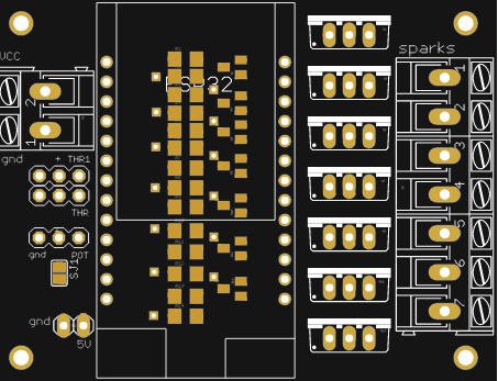
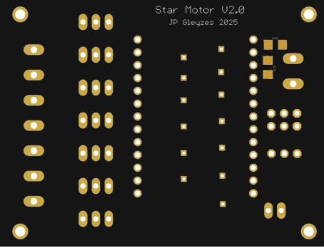
PCB version 2
I have designed a nice and compact PCB allowing to fit into an RC plane cockpit.
The PCB was again kindly sponsored by PCBWay and is as usual of excellent quality.

You can order it here: PCBWay shared project. It's cheap, delivered very fast and so professional looking!
The size is almost the same as V1 but with much more components !
You may notice that teh ESP32 board is mounted in "mezzanine" allowing to solder all the pull down resistors on the top side of the pcb just under the ESP32.
5V power is coming fromthe BEC of the ESC via the throttle channel (THR or THR1). Solder the solder pad SJ1 to allow this behavior. Then connect the 5V to the battery female plug on the ESP32 board.
First test with a single "glow plug"
This video will demonstrate the system running with a single glowing plug. Software is simulating the throttle motion with the following law :
- no throttle = hot plug stopped
- little throttle = max glowing
- increased throttle = dimming hot plug
It will also show the excellent quality of these PCBs and how all this is soldered. Thanks PCBWay!
software
software is quite simple and source code is available on my github pages
To compile this code you will need version 1.0.6 of Expressif ESP32 boards and select Wemos Lolin32 board.
There is nothing special to say for this simple code. Most of the "clever" part is when applying power to the plugs.
void cycleSparks() {

  if (Vbat > 3.5) THR = speedRaw;
  else THR = 0;  //will stop sparks if battery is low

  power = maxPower + 200*Vbat -800 ; //linear fit from 1780 to 1680 when Vbat goes from 4.0V to 3.5V
  if (power < 1500) power = 1500;
  /// map(value, fromLow, fromHigh, toLow, toHigh)
  dutyCycle = map(THR, startThr, 1000, power, MIN_POWER);
  if (THR < startThr) dutyCycle = 2047;  //will stop sparks is throttle is low
  for (int i = 0; i < 7; i++) {  //else output PWM on each spark
    ledcWrite(channels[i], dutyCycle);
  }
  if (THR > 0) {
    Serial.print("switch on spark (throttle / dutyCycle / maxPower ) ");
    Serial.print(THR);
    Serial.print(" / ");
    Serial.print(dutyCycle);
    Serial.print(" / ");
    Serial.print(maxPower);
    Serial.print(" V bat = ");
    Serial.println(Vbat);
  }
}
Battery voltage is read and used to shut down the glowing elements when it is too low (to protect against under discharge).
Throttle power is mapped between maxPower and MIN_POWER. maxPower is tuned with the battery voltage in order to balance voltage variations of the battery.
 This formula has been tuned on our glowing elements and should be refined for other batches as resistivity of each plug may vary quite a lot...
power = maxPower + 200*Vbat -800 ; //linear fit from 1780 to 1680 when Vbat goes from 4.0V to 3.5V
Here is the result when using a poor 1s3p 18650 battery made with old battery packs...
This is the reason why we only get 7A from this pack which is barely enough to glow the glow plugs...
However we can clearly see the "throttle effect", plugs only glow when throttle is low and decreases when throttle increases !
For calibration purposes, follow this procedure and use this excel sheet
- start with only one plug (as they are expensive and may easily blow if too much voltage is applied).
- Then use a fully charged battery at 4V.
- Using the serial terminal send the command : Max=1950 to the board. This will set up the maxPower value to a quite small value.
- now connect the plug and look at the filament
- it should be very dim (even not glowing at all)
- decrease maxPower sending a smaller value (10 by 10 steps is safe)
- do this until you get a nice (red cherry) glow.
- now decrease voltage of the battery and check that filament color remains pretty much the same. if not, slightly modify the formula above for voltage compensation.
- now connect the other plugs and check that they all behave similarly
We are ready for the final tests !
Serious game
Here is the setup for a "serious" test on the bench.
Motor is fixed on a bed, hot plug preheater is connected on a big 10Ah 1s li_Ion pack.
The propeller is an impressive 18x6 wooden one.
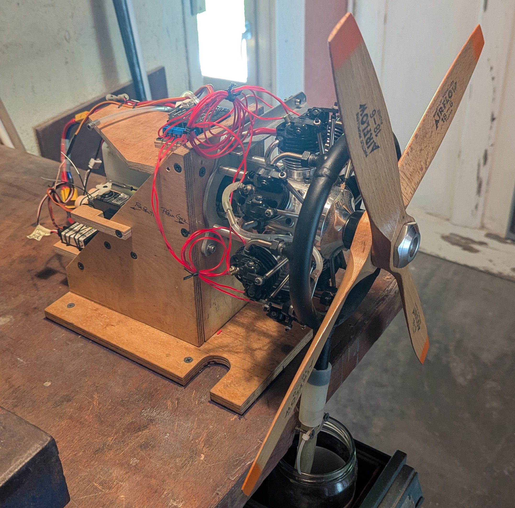
What you will see now is a "cold start". Meaning that the motor is at ambiant temperature 15°C and will start with the pre heater.
Let's enjoy the music of this marvel !
Obviously the preheater is working, but we wanted to see how efficient it was. So here is a test with the motor already hot, minimum throttle and then disconnecting the pre heater.
So the efficiency of the system has no longer to be proven. The motor can be started at very throttle and keeps a quiet rythm. If we disconenct it then it stalls which was expected !
To finish this project here is a warm start done manually. And , for the sake of art, the video will slow down between 20 and 30s for you to enjoy the motion of the rocker rods !
appreciate the wonder of this precision mechanics !