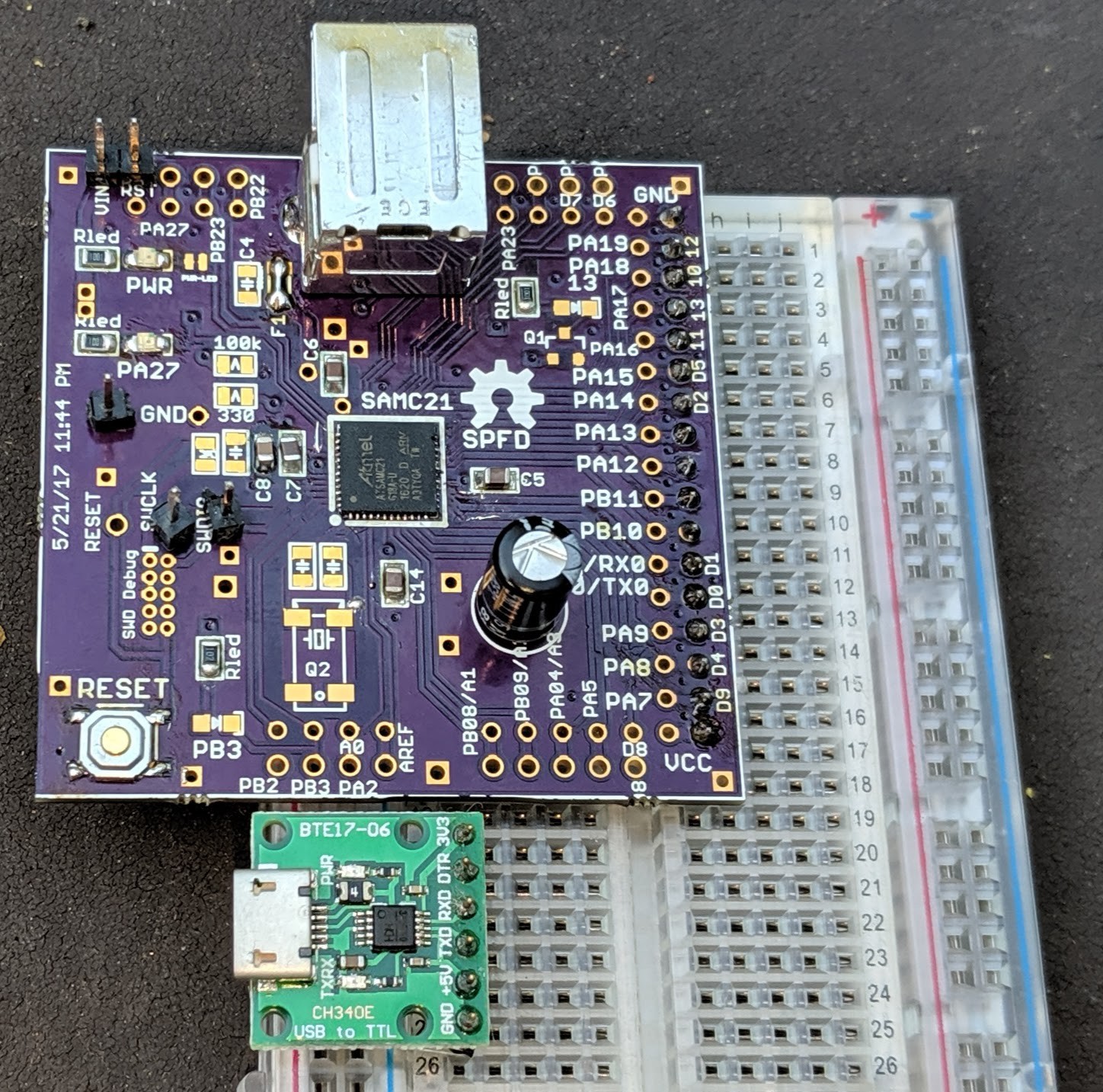
Simple breakout board for Atmel's SAMC 5V ARM chip.
To make the experience fit your profile, pick a username and tell us what interests you.
We found and based on your interests.
Aside from Microchip apparently deciding to rename all the peripheral registers, going from "running" to "blinking the LED" went pretty quickly. Running at 48MHz, 2 wait states, and outputting the clock on its respective IO pin. Woo hoo!
int main(void) {
// Clock at reset is set to the internal 48MHz clock, divided by 12.
NVMCTRL_REGS->NVMCTRL_CTRLB |= NVMCTRL_CTRLB_RWS(2); // 2 wait states for 48MHz
OSCCTRL_REGS->OSCCTRL_OSC48MDIV = 0; // no division
GCLK_REGS->GCLK_GENCTRL[0] |= GCLK_GENCTRL_OE_Msk; // output the clock on a pin
PORT_REGS->GROUP[0].PORT_DIRSET = GCLK0_OUT;
PORT_REGS->GROUP[0].PORT_PMUX[GCLK0_PIN/2] |= 7; // PMUX H is clkO
PORT_REGS->GROUP[0].PORT_PINCFG[GCLK0_PIN] |= PORT_PINCFG_PMUXEN_Msk;
PORT_REGS->GROUP[0].PORT_DIRSET = LED;
while (1) {
PORT_REGS->GROUP[0].PORT_OUTTGL = LED;
mydelay();
}
return;
}
After fiddling with tools a bit (it looks like neither AS7 nor MPLABX 5.1 is quite up to using a PICKit4 with SAMC21), I have the board responding, have uploaded an empty C program, and can single-step through the C runtime startup code.
(Using (upgraded) MPLABX 5.25 and the PICKit4, on MacOS...)
So that's pretty significant! Next up, Blink!
Well, there it is, with what might be about the minimal set of components needed to attach a debugger to see if it works. Applying USB power (remember, there is no actual USB on this chip :-( ) causes the power LED to light up, and didn't release any smoke or cause my Mac to complain about drawing too much power, so that's a good sign.
The QFN soldering (my first time!) went better than I expected. I used the "Maker Paste" low-temp solder from Adafruit, and a hot plate. I guess I used too much paste, because I got solder balls around the outside, but they cleaned up pretty easily, and as much as I can actually see looks really good. (and, it didn't blow up!) https://forums.adafruit.com/viewtopic.php?f=42&t=154682
(A couple of people have recently "liked" this project, so I thought I should post an update...)
I'm ready to call the existing PCB design a failure.
Aside from the non-presence of USB in the chip, the PCB was designed with the "sweet spot price" prototype PCB of 50x50mm. Since then, most of the cheap vendors have increased the max size of low-cost boards to 100x100mm, which would easily fit a much more "comfortable" design (Arduino Shield compatible, for instance.)
I haven't gotten around to actually trying to build one of the boards (scary QFN pinouts!), and now I'm not even sure it's worth trying :-(
So it turns out that i didn't read the datasheet carefully enough. A "quick" look showed that the SAMC21Gxxx was exactly the same as the SAMD21Gxxx, except for the 5V-ness. All the pins were in the same place, and etc.
But it turns out that none of the SAMC parts have a USB controller! SAMC21 has CAN on the same pins that SAMD21 has USB. I guess I can't blame anyone but myself, but I wish Atmel had used more distinguishing part numbers. Sigh.
(Found while looking at SW. I guess the boards are still usable.)
I sent the design out to OSHPark, and have received real boards that look pretty good (the slots for the USB connectors didn't work, but everything else looks pretty good.)
Gee, those pads look awfully tiny "In Real Life", compared to how big they looked blown up on my monitor when I was working on them in EAGLE! I'm reviewing tutorials on QFN soldering without fancy equipment, and have practiced with some simpler SMT components and the hotplate that I own; that seemed to go "ok", but I don't really have any "practice" QFN chips (I've got some SSOPs) or boards (though I did find some SO-sized scrap boards...)
And it seems that a toothpick is probably "too big" a tool for applying solder paste...
Create an account to leave a comment. Already have an account? Log In.
Ah. I had noticed the "Divide and Square Root Accelerator" at some point, but not to the degree that I also noticed it WASN'T present on SAMD chips. No, I haven't played with it at all.
There is this, though: https://www.quinapalus.com/qfplib.html
Thanks, that seems like a more portable alternative!
Thanks for picking this project back up! Just by coincidence, I am in the middle of bringing up a SAMD21 board with MPLABX, and you left enough bread crumbs to help me find my way :-)
Good work!
Any particular reason for choosing QFN instead of the TQFP? I find that to be easier to drag solder, which means no need for paste.
Become a member to follow this project and never miss any updates
@WestfW I was looking at some 'DIVAS' code is in the initialisation for a SAMD21 that I have inherited. Looking up DIVAS I find out it doesn't feature in SAMD21 but it does in SAMC21, which made me think of this project. I don't mean to necro it but have you played with DIVAS at all? I imagine it could make the SAMC21 a good option for some applications where a hardware divide/sqrt in an M0+ core is desirable (I just can't thick what they would be specifically!).