 James Newton
There is too much. See the project at:
https://github.com/JamesNewton/HybridDiskEncoder
0%
0%
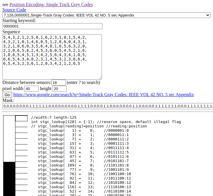
Hybrid Disk Encoder
More than 100K CPR, lasercut, Arduino, cheap and easy to make, absolute position? Could it be? Yep.
Become a Hackaday.io member
Already have an account? Log in.
Just one more thing
To make the experience fit your profile, pick a username and tell us what interests you.
Pick an awesome username
hackaday.io/
Your profile's URL: hackaday.io/username. Max 25 alphanumeric characters.
Pick a few interests
Projects that share your interests
People that share your interests


 shlonkin
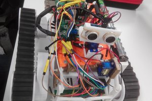
 Alan Chambers
 ZaidPirwani
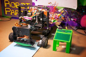
 EK
EK