Julius Curt
Time is an abstract concept, especially for toddlers who lack the intuition we adults take for granted. When I tell my toddler, "You have 5 more minutes to play," I can only imagine how meaningless that might sound to him. To bridge this gap, I designed and built a 3D-printed visual timer. This timer uses light tiles, an OLED screen, and a rotary encoder to make the passage of time more tangible and intuitive.
I also did this project as a 1-day project challenge, completed in just about 8 hours (with some extra time for 3D printing). Here's how it all came together. I really could've used a visual timer to track the 8h time for this too.
This worked better than I expected, the kid checks it from time to time and even ran to brush his teeth when he noticed the last cell went out. But I'm getting ahead of myself here, let's start from the beginning.
Concept and Goals
The idea was to create a countdown timer with a simple, child-proof interface. Here's what I envisioned:
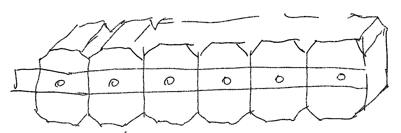
- A light-based progress bar in reverse.
- A small OLED screen for the literate users.
- A clickable rotary encoder for various inputs.
- A compact, 3D-printed enclosure to hold everything together.
The timer needed to be robust enough to handle a curious toddler’s tinkering but intuitive for adults to use.
Hardware
The hardware for this project is straightforward and budget-friendly:
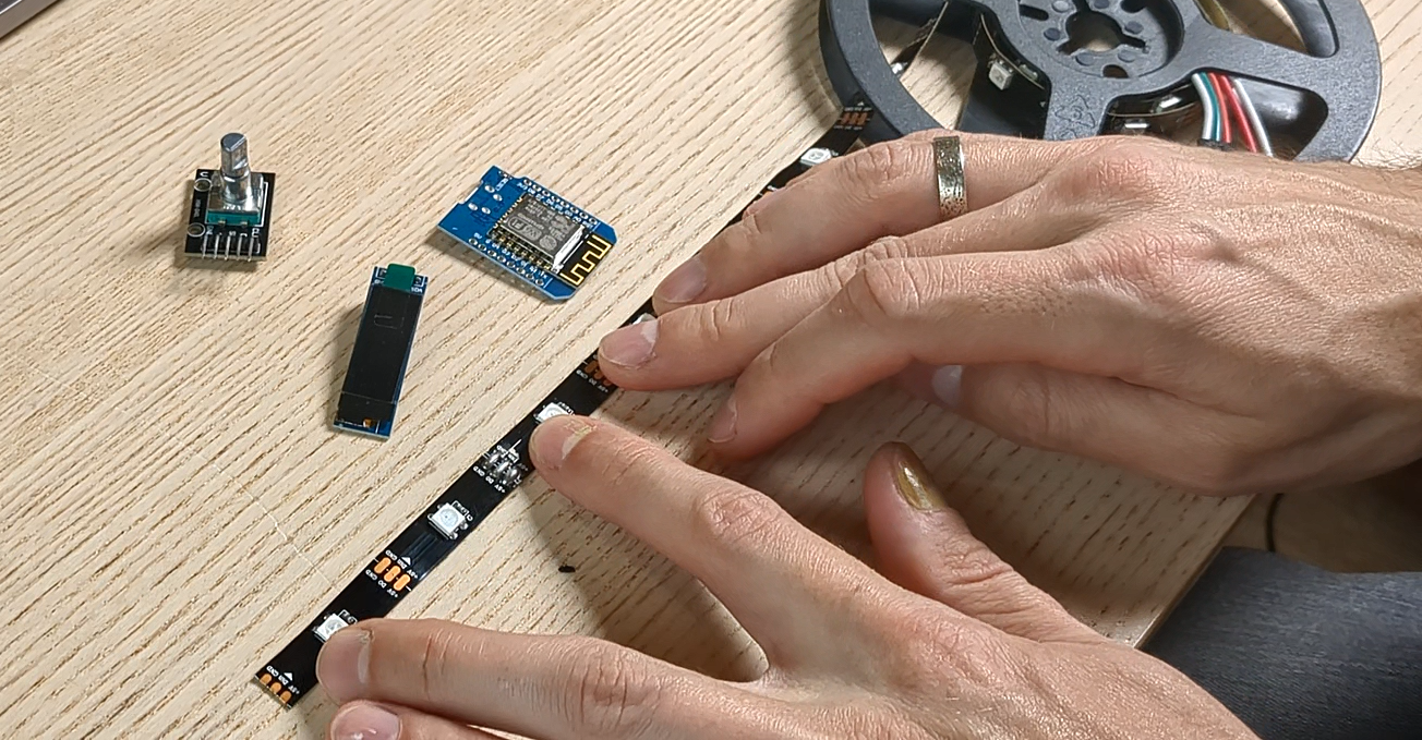
- LED strip: 6 individually addressable RGB LEDS (WS2812b), 30 LEDs/meter density
- Microcontroller: Wemos D1 Mini (ESP8266) for its compact size and versatility
- OLED screen: A small I2C display (128x32)
- Rotary encoder: Clickable, for user input (KY-040)
All components are widely available, cheap and suitable for a beginner-friendly project.
Design and 3D Modeling
I started by modeling the enclosure in CAD software. To streamline the process:
- Parametric design: I defined user parameters for dimensions, ensuring reusability and easy adjustments if needed.
- Existing models: I downloaded step files for all the modules from GrabCAD to avoid modeling from scratch.
- Iterative testing: Partial prints were used to verify fit and alignment before committing to full prints.
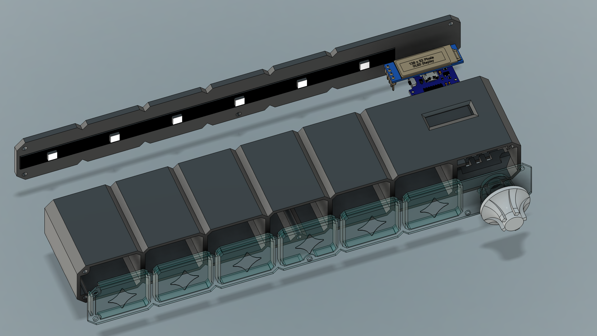
The enclosure was designed to house all components securely. For the light tiles, I created compartments that matched the LED spacing, and a front panel to diffuse the light.
Firmware
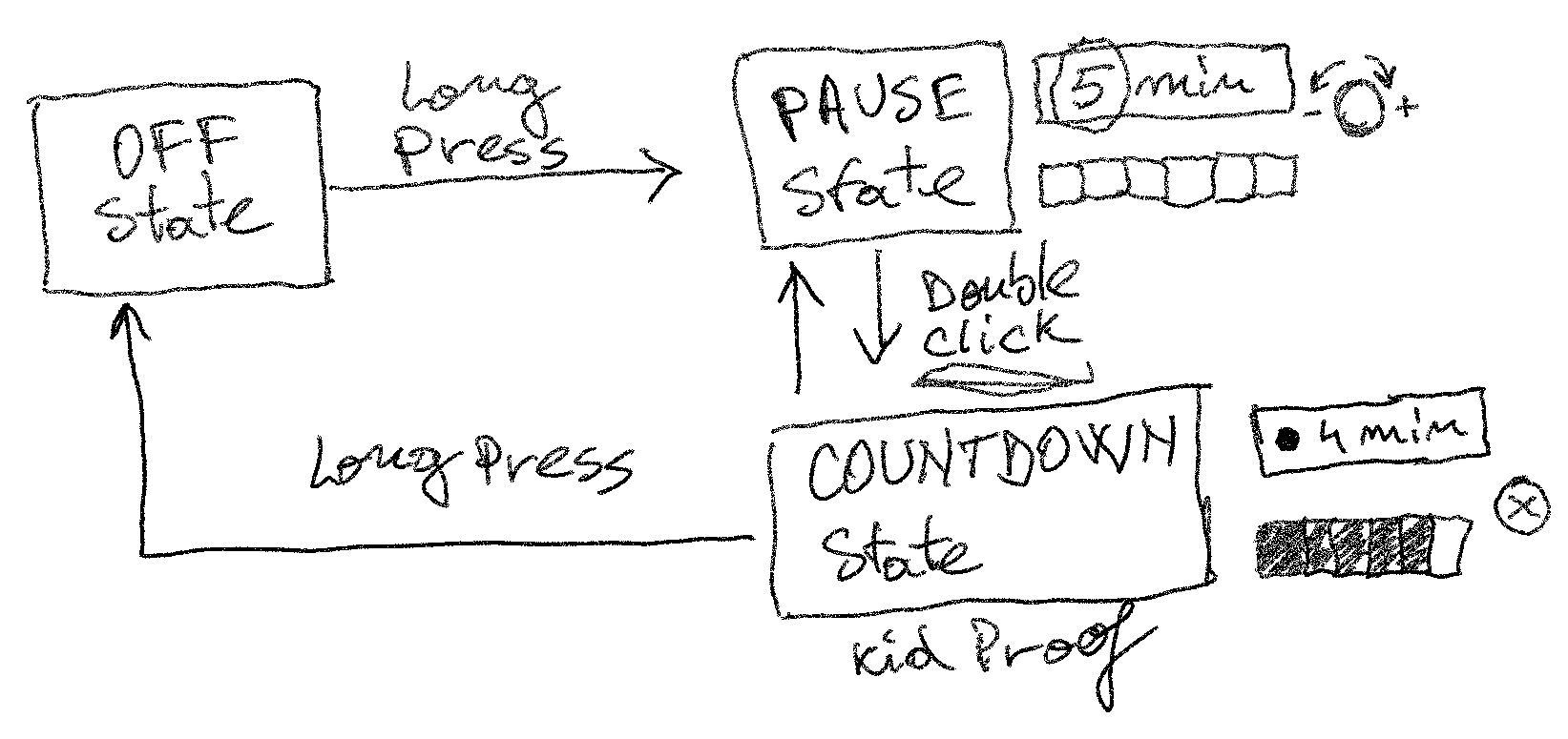
The firmware controls three primary states:
- Off State: everything is turned off, lights, screen etc.
- Pause State: Time can be set using the rotary encoder and the screen
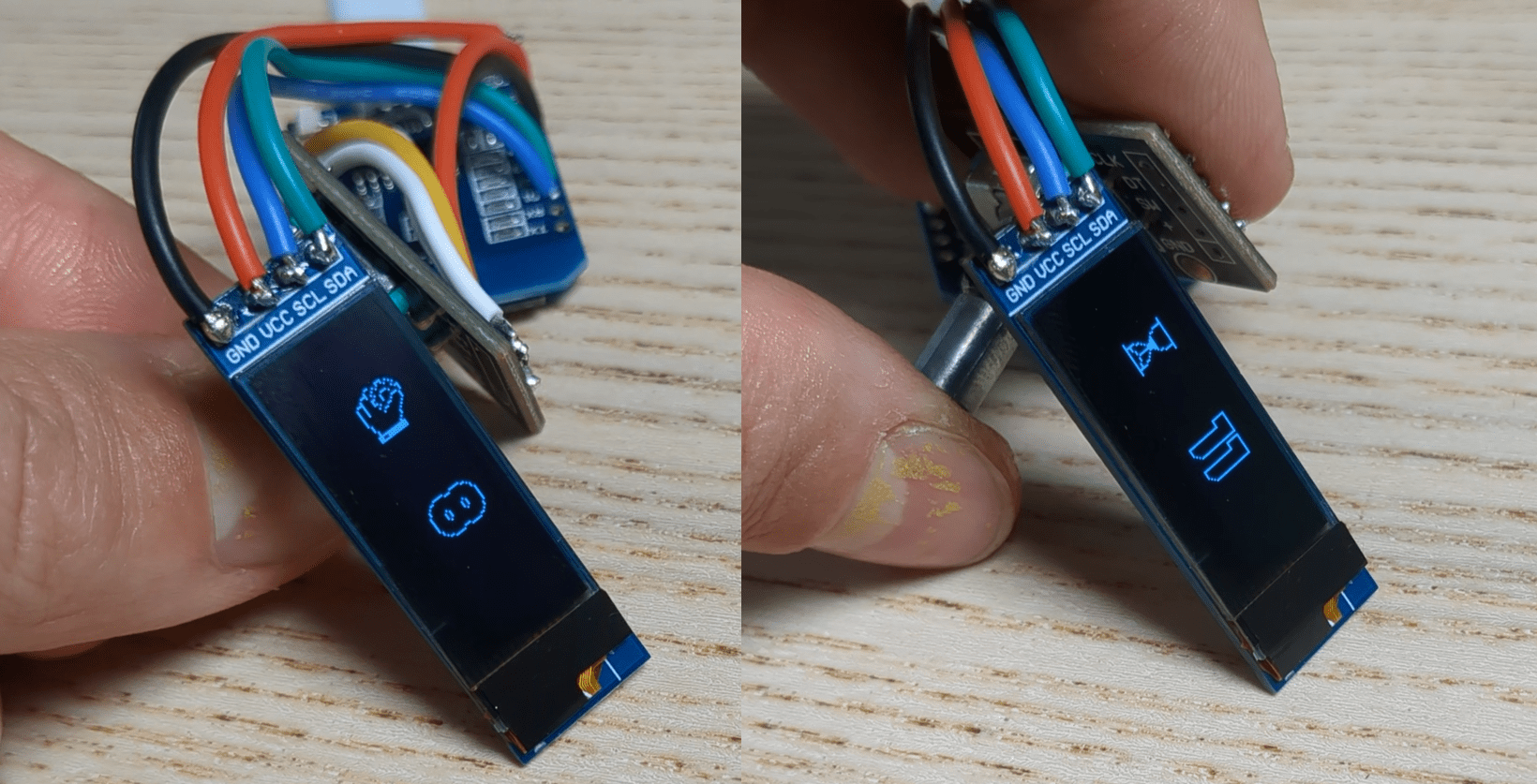
- Countdown State: The timer runs, LEDs go out progressively, the inputs are locked to prevent tampering, screen displays remaining time in minutes
Using the OLED display’s graphics library, I added icons for the states and selected a bold font for easy readability. The rotary encoder’s interrupts ensured smooth and precise control. Debugging the logic and edge cases was time-consuming, but it was rewarding to see the system function seamlessly.
Assembly
With the 3D-printed parts ready, assembly was straightforward. I wired everything up trying to minimize the wires slack, most importantly for the screen because the slack will go in the way of the 1st LED if too long. I'll try to fix this in the next version.
The whole assembly comes in from the front through the body, the encoder remains in the front and the screen goes out through the back.
- Encoder: Screwed down to the front plate
- LEDs: Applied to the back panel
- Screen: Press-fit into its designated slot
- Microcontroller: Mounted with epoxy putty for a firm, permanent hold
After some tweaks (reprinting the face panel for better light diffusion) everything fit together perfectly.
Wrap-up
This visual timer turned out to be a fun and functional solution for helping my toddler understand time. It’s simple, engaging, and durable enough for daily use. But this is not only useful for kids, I can still use it for myself whenever I want to set...
Read more »
 sjm4306
 Alistair MacDonald
 Tim S
Tim S