 Zachary Murtishi
Changes from the original Mancala game include:
- Change from 5mm through-hole LEDs to SMD-0805 LEDs
- Addition of a USB interface (via FT230X) to allow future interoperability between the board and a potential PC application
- Maybe allow the use of a high-performance CPU player running on a host PC?
- Button interface solution has swapped from a scan-matrix to a TCA9535 I2C I/O expander
- MCU has been switched from a PIC18LF2420 to an ATtiny3224.
- Smaller footprint PCB with 4-40 threaded holes to allow for more flexible mounting solutions
- Addition of a 4-position DIP switch to allow for potential of different game modes.
This project is based on an earlier project and retains all its features, including a two-player mancala game featuring the full rule set and game parameters, the ability to alter the brightness of the LEDs through a TLC59116 LED driver, and the 16-LED/16-button interface of the original design.
The board is a 4-layer design fabricated and assembled by JLCPCB. The board was designed using KiCad 7.0. Firmware for the ATtiny3224 was developed using MPLAB X and the avr-gcc compiler. A PICkit 5 is used to program and debug the MCU over UPDI.
 J.C. Nelson
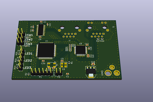
 charliex
 TinLethax