 Trey Weber
-
1Step 1
The Frame:
![]()
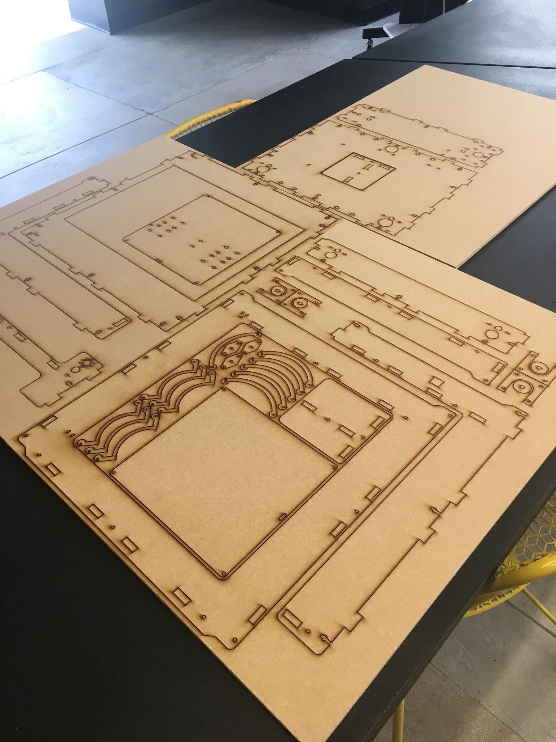
I laser cut the frame out of three sheets of 24"x18" MDF. The design is for 1/4" thickness. It could be made out of a different thickness, but your results will vary with rigidity and the press fit tabs will need to be edited. The tabs will fit together snugly, with a very little bit of sanding to get the tabs just right.
![]()
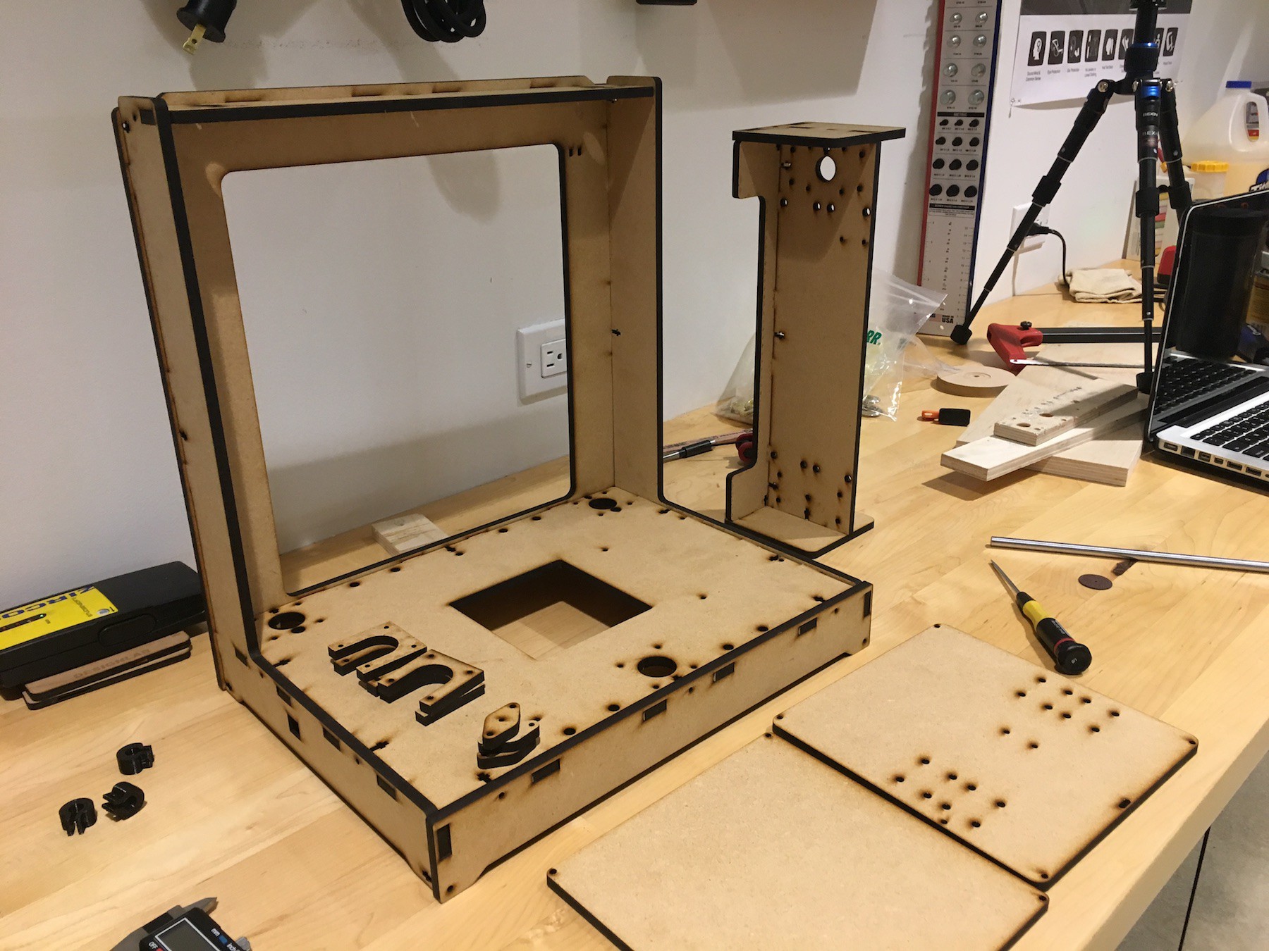
Here you can see how the frame will be assembled. There is a main body assembly consisting of a front, top, back, base, and "L" side plates.
On the top right is the X/Z axis assembly. This will eventually be mounted on rails that will slide through the two back holes in the base of the main assembly. Stepper motors under the base will control Z height, and a single stepper on the X/Z axis assembly itself will control the X direction.
Lastly, on close right you can see two square plates that will be the printing bed itself. This will be movable in the Y direction with another stepper motor placed underneath the base.
Even though everything fits together well with the press fit tabs, there are slots for hardware and will the weight of all the parts that will eventually be mounted, screws will be necessary to maintain rigidity.
An approximate list of hardware is as follows:
- 30x M3 10mm bolts
- 50x M3 16mm bolts
- 10x M3 30mm bolts
- 15x M3 40mm bolts
- 14x Hex Female 8mm M3 spacers
- 80x M3 flat washers
- 80x M3 nuts
- 15x M4 12mm bolts
- 10x M4 20mm bolts
- 20x M4 flat washers
- 20x M4 nuts
- 2x M5 30mm bolts
- 2x M5 nuts
- 16x M6 12mm bolts
- 2x M6 flat washers
- 2x M6 nuts
-
2Step 2
X/Z Axis Assembly:
![]()
First the rods had to be cut to size in order for the stepper motor to fit on the right side. Being hardened steel rods, I used a Dremel with a reinforced cutting wheel. The biggest issue became mounting the extruder and mounting the idler so that the belt system had as little friction as possible. I ended up mounting the extruder on a generic aluminum bracket and fastening two bushings to the back for the rods to slide through. At this point I'm noticing how cheap the MK8 extruder seems to be, so I'm already thinking about replacing it.
![]()
The stepper motor mounts upside-down on 4 spacers that were included in the original laser cut file. This allows the pulley room to guide the belt below the extruder bracket and between the linear rails. I had to get a little creative with mounting the idler on the left side, as well as attaching the belt to the extruder assembly. To do this, I just trimmed a couple steel brackets with the cutting tool and drilled new holes for mounting. The idler is just mounted with a bolt and a couple washers. The bearing in it is not as smooth as I'd like, so this also might need replacing later.
![]()
On the back you can see where the two leadscrew nuts were mounted on the top, and the four linear rail bushings on the back. Note that these bushings are a smaller version of the other 6 used in the rest of the 3D printer. This is because these are thinner and fit better in the space provided. This picture should give you an idea of how the X/Z assembly will eventually mount on the vertical rails and lead screws.
-
3Step 3
Body Assembly:
![]()
![]()
Final body assembly was fairly straightforward. The most time consuming process was cutting and fitting the timing belts. First, three stepper motors are mounted underneath the base: two in back (Z axis) and one in front (Y axis). Two Z endstops are mounted on the top, with a third on the base. The upper X/Z axis assembly is simply threaded with the leadscrews and then slid onto the linear rails for stability.
![]()
Here you can get an idea of how the printing bed works. Ignore the 3D printed rail mounts, the aluminum ones were too tall and limited the travel in the Y direction, so it was either 3D print my own or add spacers in between the bushings and the lower bed platform. The most important part of the bed assembly is the springs between the two platforms: without these it will be impossible to print because there will be no way to make your bed level in reference to the extruder. The Y axis pulley is attached to the frame via a simple nut, bolt, and bearing. A proper idler will probably be at the top of my list of improvements.
-
4Step 4
Software:
![]()
The Arduino MEGA with the RAMPS shield runs on a program called Marlin. It's essentially a compilation of Arduino sketches that can be configured to a specific DIY or commercial 3D printer. A schematic and general instructions on how to install Marlin are uploaded into files. The most time consuming aspect will probably be configuring your endstops. For example, to add a second mechanical Z endstop you need to first activate the port, enable the homing direction, and establish your endstop logic (is the switch normally open or closed?). Other issues that came up for me was utilizing the male header for the second extruder as a second Z axis driver, software endstops, and steps/mm for each motor. The possible combinations of settings are endless, however as a beginner this gave me a very in-depth intro to configuring a mechanical device.
Marlin does an excellent job in their program of commenting each line of code and it's definitely a firmware geared towards beginners. Most of this process was testing a setting rather than programming, because it's usually as simple as un-commenting a line of code or changing a boolean.
-
5Step 5
First Prints:
![]()
![]()
Surprisingly accurate (0.8% error) considering I had to basically guess all the extruder settings in the slicer and e steps/mm. This can definitely be improved by adjusting the extruder multiplier.
Benchy:
![]()
![]()
As you can see, the layering and detail are actually, really good all things considered. What's terrible is the retraction, and even after reprinting this particular model about 12 times I could not find any settings in Cura that improve this at all.
The reason for this is the complete lack of a cooling fan on the hotend to cool the filament as it extrudes. A fan is on order and should be here in a couple days, and I can see if that improves the spider-webbing. Ignoring that for now, I'm actually pretty happy with how well this has printed so far considering there is still a fair bit of tinkering and calibration to be done.
Cartesian Style 3D Printer
This project will be a cartesian style 3D printer, geared towards beginners or individuals who want to explore 3D printing as a hobby.


Discussions
Become a Hackaday.io Member
Create an account to leave a comment. Already have an account? Log In.