An online image like this kicked it off:

The LCD is driven with a SPI-like interface, DATA, WR & CS plus an LED pin to control the backlight. The 16-segment characters are fortunately symmetric with respect to rotation (excluding the decimal place):
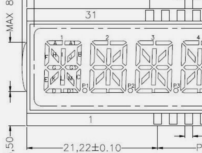
The code defines characters etc in the usual (upright) way, but the segment bit flags are transformed (rotated) before sending to the display. For example segment ‘A’ above would be mapped to ‘E’ with the display rotated anti-clockwise so character #1 is at the bottom.
Data structures in the code represent the rotation of segment bits and also the physical arrangement of segments allowing me to treat them as “pixels” and drive the animations.
As the time updates, digits which need to change first disappear, segment-by-segment, character-by-character, from the bottom up. Segments tumble from their original location off the bottom of the display, creating a “waterfall” effect. Replacement digits also appear segment-by-segment, character-by-character, with the segments “filling up” from the bottom.
The source of the sketch is on GitHub.
The hardware side is pretty trivial: a Tiny Leonardo (https://www.jaycar.co.nz/leonardo-tiny-atmega32u4-main-board/p/XC4431), the LCD, an RTC, an LDR to dim the display in low ambient light (it’s bright) and two push-buttons with voltage dividers (on a single analog pin).
Messing about in the software was the easy bit, I dithered on the enclosure for a while, in fact I detoured to whip up a Tiny Game using a DM8BA10 and treating the segments as pixels (SegAssault, https://hackaday.io/project/197722-segmentassault). But eventually I settled on a vaguely “sunburst” design, initially visualised in OpenSCAD:
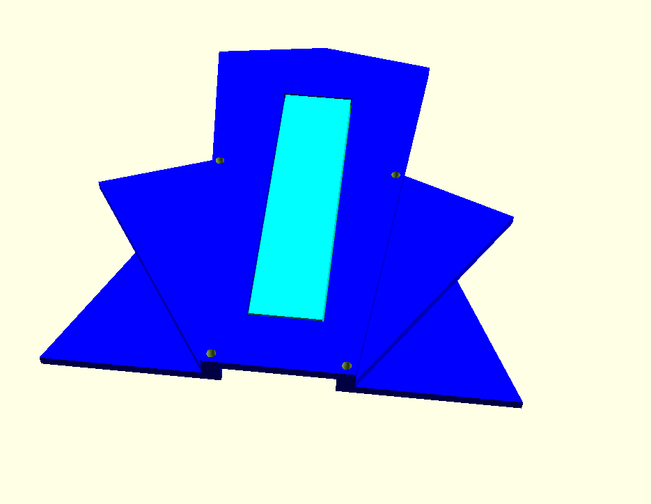
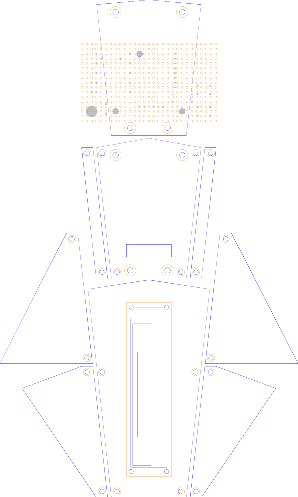
But then I got on to designing it for cutting, in Inkscape using my Inksnek Python code (https://github.com/funnypolynomial/inksnek) .
The code creates the laser-cutting pattern (this is DEVEL mode so it also shows the PCB location, outline of LCD etc):
and also an approximate render of the assembled plates:
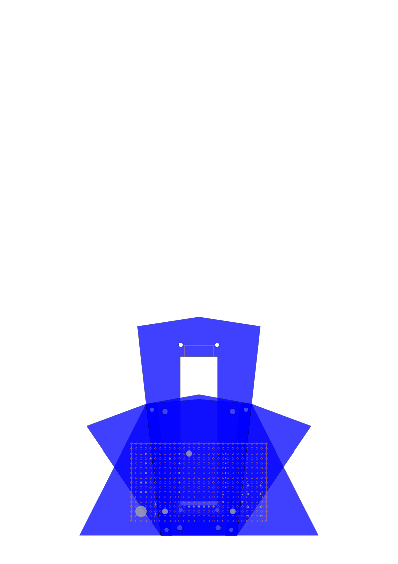
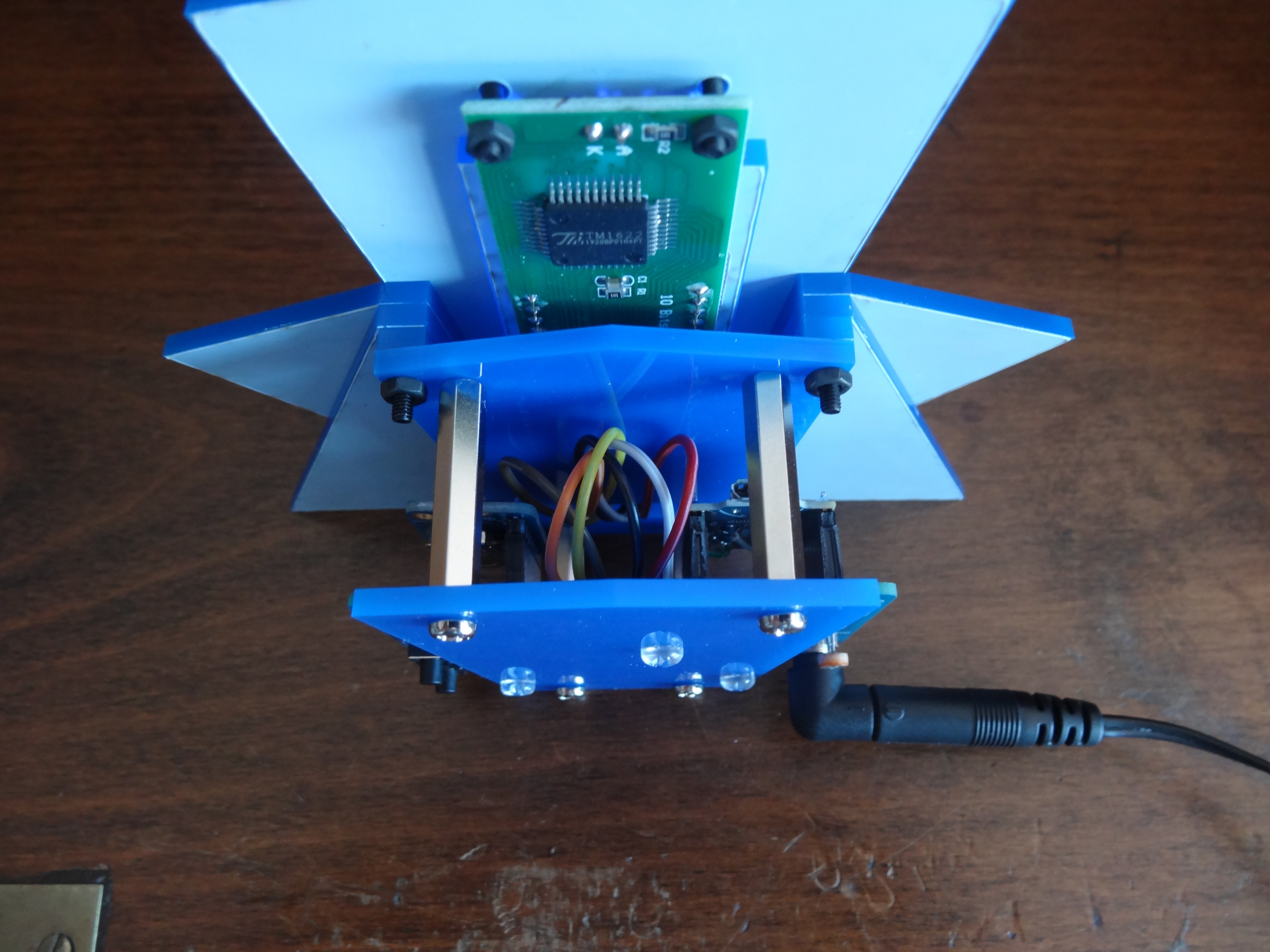
The enclosure is just a complicated stack:
5 plates at the front creating the sunburst facade. The large centre plate has the LCD attached with M2’s.
Behind that stack are a couple of spacers for clearance then the first back (PCB) plate. These are all connected via 4 M2.5 bolts. The first back plate is connected to the second (rear-most) plate via M3 bolts and 20mm standoffs. The PCB is mounted to the front side of the rear plate via M3 nylon bolts. The PCB protrudes either side of the back plate, giving access to the DC power socket and two push-buttons. It also exposes the LDR.
Some videos:
More photos on Flickr
C++ Arduino code and Python enclosure code are at GitHub.
 Mark Wilson




 ogdento
 Tahmid
 SAYANTAN PAL
Hello Mark, I built the waterfall clock and it works very well. Then I want to change the time display to 24 hours. In Config.H in line 24 I changed it to 24 H and saved it. After uploading, "FALLING" appears on the display and then nothing. What am I doing wrong? Please help.
Regards
Norbert