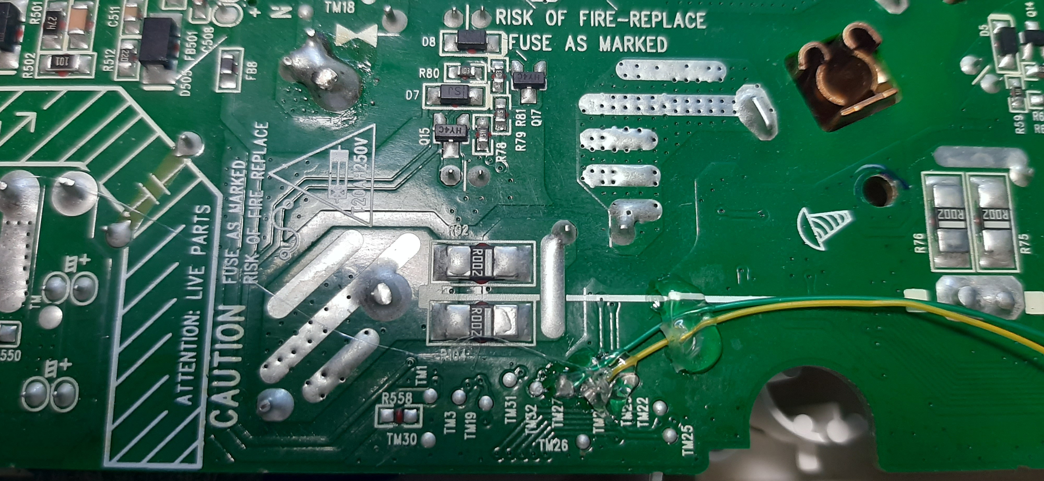
Overview
Device Internals
Investigating
Hacking
Result
Open Points
Control the power plug from a simple web server
To make the experience fit your profile, pick a username and tell us what interests you.
We found and based on your interests.
I2C_Relay4_OFF.csvms-excel - 1.25 kB - 12/25/2024 at 12:48 |
|
|
I2C_Relay1_OFF.csvms-excel - 1.25 kB - 12/25/2024 at 12:48 |
|
|
I2C_Relay4_ON.csvms-excel - 1.25 kB - 12/25/2024 at 12:48 |
|
|
I2C_Relay1_ON.csvms-excel - 1.25 kB - 12/25/2024 at 12:48 |
|
|
I2C_Relay2_ON.csvms-excel - 1.25 kB - 12/25/2024 at 12:48 |
|
The following are still open and need more research (when time allows):
Here is the final result - Video link
My ultimate goal is to have a simple app that talks to an API to control the device, and the opened port 30300 looked promising. So, I tried to check the binary file for clues regarding what APIs are used but, I could not find anything useful.
So, I turned to the LED-I2C bus that controls the relays. Using the amazing "Bus Pirate" and the logic analyzer captures, I was able to control all the relays in the same way the SoC does by sending the frames in the capture files.
The only problem is that the I2C bus can have one master only which is the SoC. So, for the bus pirate to work, I had to put the SoC in reset before sending the frames. But, in order to operate the device normally, the SoC must be running.
Remembering that the I2C bus is transferred from the Control board to the Power board via the flat cable, I cut these two pins from the cable, and soldered two wires on the Power board itself thus, isolating this bus only from the Power board.
This worked perfectly without the need to reset the SoC.
Now, that I can bypass the SoC, all what remains is to add "Internet" part to the "Things".
The ESP-01 is a tiny and capable module, and fits perfectly inside the plug housing. Using GPIO0 and GPIO2, I connected the ESP-01 to the I2C test pads on the Power board. With a simple Arduino sketch, I can control the power plug from any phone.
After identifying as many components as I could, it is time see how things work. So, I got my $10 logic analyzer and $20 FT4232-56Q module out and got to work.
I connected the three I2C buses to the logic analyzer and the two UART ports to the FT4232 module, then turned on the device. I turned ON/OFF some relays while recording everything, and below are the logs.
1 = ON , 0 = OFF
The plug consists of three boards; Control, Power and USB.
The control PCB is the brain of the plug and has the following components:
The controller is an RTL8711AF which is "ARM Cortex M3 SINGLE-CHIP 802.11b/g/n 1T1R WLAN SoC".
The SoC has several GPIO pins, I2C, SPI, UART and even NFC peripherals.
The input is 18V coming from the Power board.
There are several voltage regulators to generate the 5V, 3.3V and 1.2V required by the USB and the SoC.
The Power PCB has several interesting components which, unfortunately, I could not identify any of them. I was able, however, to discern their functionality from their connections.
Unfortunately, I could not read anything of the chips.
The 
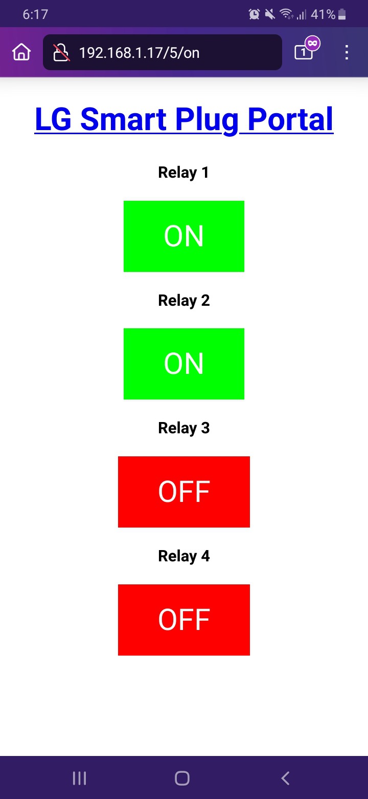
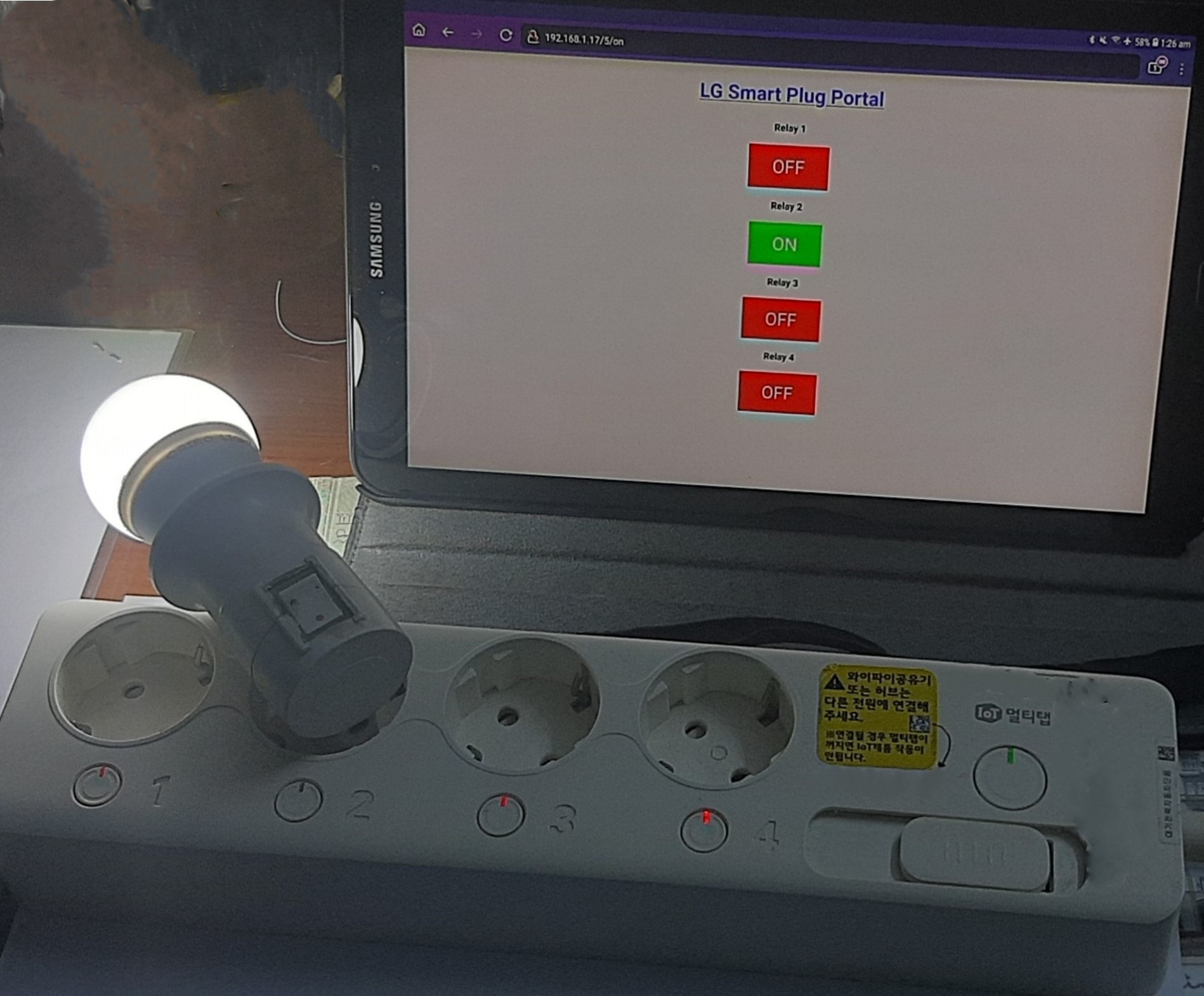
LG Smart Power Plug MTTL-W01 (called Multitap) is 3.5KW power plug made by LG/TCL.
It houses a lot of nice features such as Overload power cut, Standby power cut, remote controlled via mobile application over WiFi, USB ports for charging phones and many more. It is also made from high quality materials.
So, I decided to take the matters in my own hands.
Create an account to leave a comment. Already have an account? Log In.
Become a member to follow this project and never miss any updates