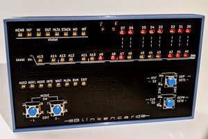
The RasPI front panel board uses a bunch of MCP23017s to provide enough GPIO pins to run the front panel. The software, pipan8l, provides commands to access the switch and light signals available in a TCL scripting environment. The commands are such as 'setsw sr 01234' to set the switch register to 01234, 'flicksw start' to flick the start switch, and 'getreg ac' to read the accumulator (light bulb signals), 'getreg run' to read the run light bulb. Makes it easy to build test scripts for diagnosing problems with the PDP.
The ZTurn I/O uses 4 circuit boards. One for slot 36 B,C,D, one for slot 35 B,C,D, one for slot 34 B, one for slot 34 D. The slot 36 board also holds the ZTurn card. The slot 35 and 34 boards piggy-back onto the slot 36 board. The FPGA code connects between the three PDP busses and the ZTurn's ARM processor bus. The three D connectors provide access to PIO instructions, the two C connectors provide DMA access and the three B connectors give the ZTurn the ability to provide extended memory. The ZTurn is basically a RasPI with an FPGA with 90+ pins instead of simple GPIO. The code for the FPGA interfaces to the three busses of the PDP-8/L to provide functionality of various I/O devices such as disk, tty, video, tape. The FPGA communicates with the ARM half of the ZTurn for access to needed files, terminal windows, etc. The FPGA also provides 28KW extended memory, and the extended memory can also be used in place of the 4KW core stack (for a total of 32KW) in case the core stack in the PDP-8/L is not functional. You ssh into the ZTurn like a RasPI and run the programs, such as z8lrk8je to load disk files into the RK05 drives, and use z8ltty for accessing a TTY or use the PDP-8/L's hardware TTY. Then use either the real PDP-8/L front panel to manually boot or use the RasPI-based panel for automated boot.

 Plasmode
 Keith
Keith
 h2w
h2w
 ajlitt