 Ken Yap
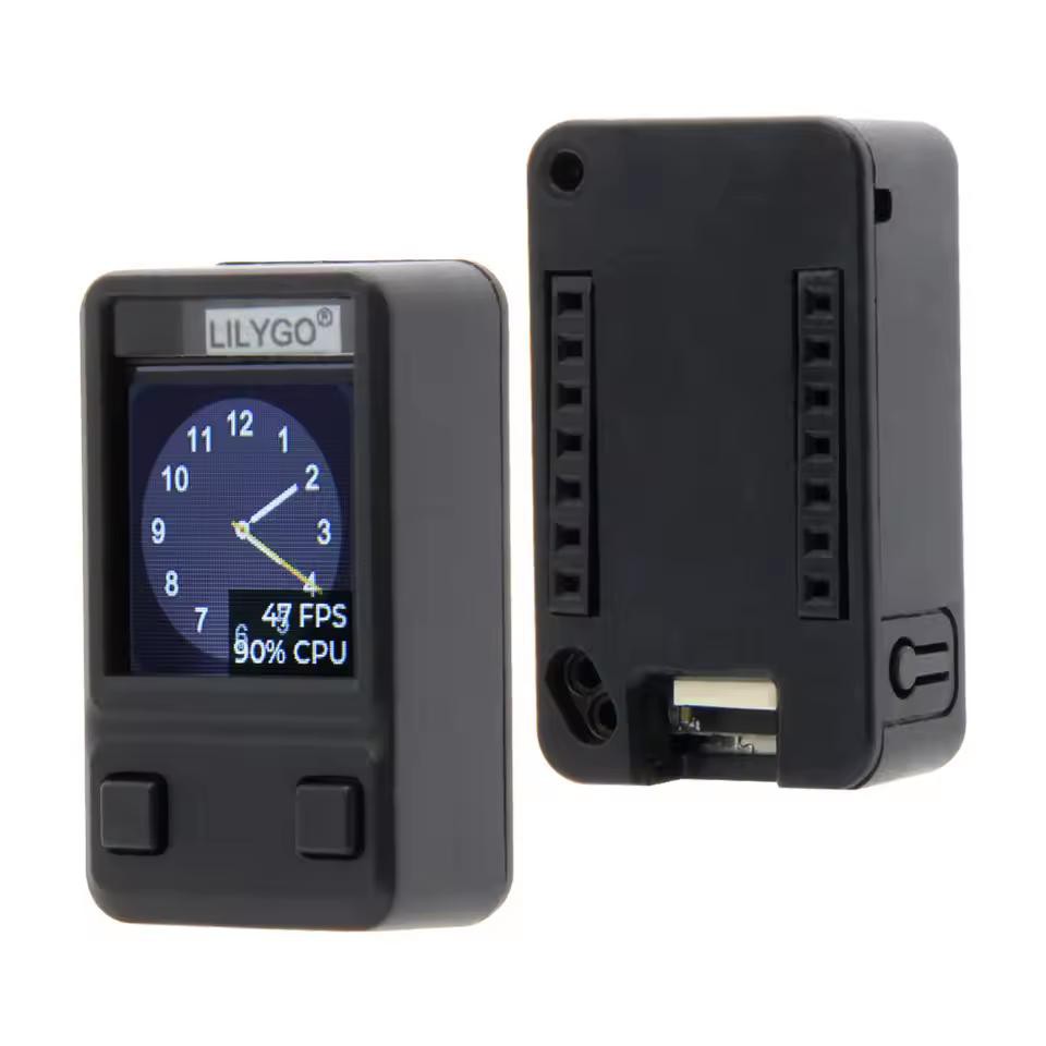
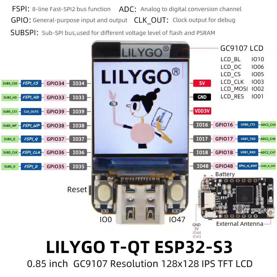
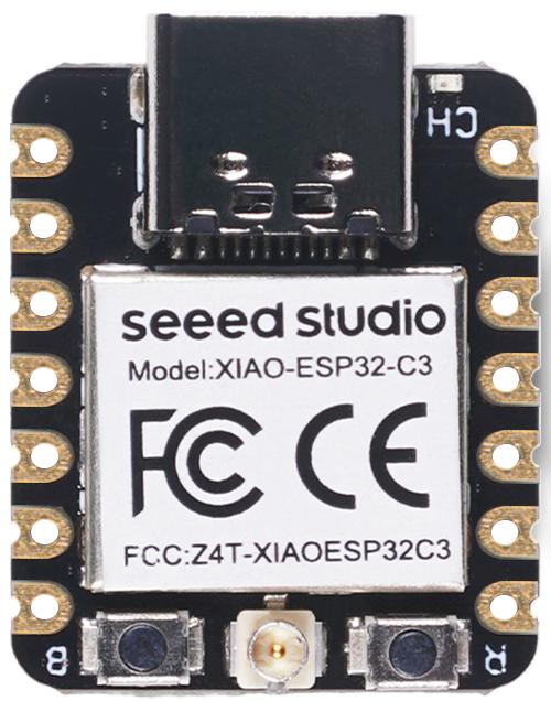
I have two motivations for this project. One is to measure the conditions in my home. The second is to use up the ESP modules that I couldn't resist buying because they were so cheap.
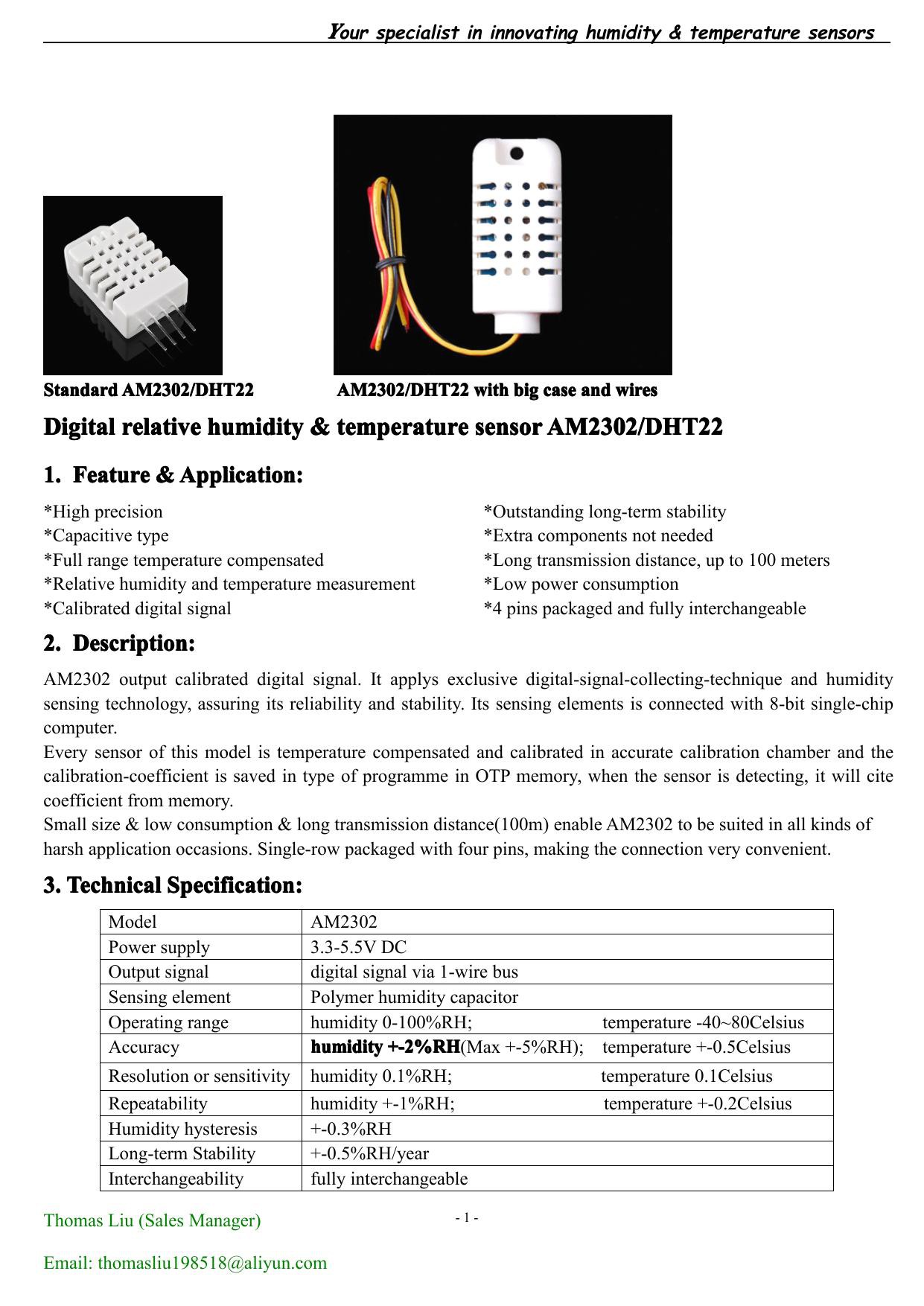
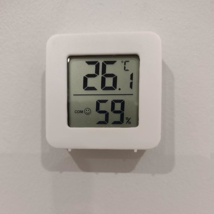
Normally temperature is the first thing that comes to mind. However it is of less importance to me because it generally stays within 24±2°C indoors and I notice when it's outside those bounds. Of more interest to me is humidity which can be stifling if too high, and cause static electricity phenomena if too low. There is UV radiation level outside which means protective clothing and headgear if too high, for the sake of the skin. Combustion products are of concern, but less now that I switched from gas to induction cooking. Cooking fumes should also be measured. So gas detectors are on the list.
There are limitations to overcome such as not wishing to have power wiring all over the place. But battery operation means paying attention to the power budget.
There is no lack of similar projects to draw inspiration from. I just have to concentrate on what interests me.
This is an exploratory project with no well-defined endpoint so I'll publish a series of logs as development progresses.


 Marek Więcek
 Maker-fabs-J
 Pure Engineering
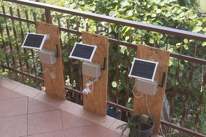
 Sergio Ghirardelli