 Johan Berglund
-
1Step 1
Prepare your frame of choice. A non conductive frame material like wood or plastic is required. Wood is probably the best choice (no risk for melting when we solder). Holes for lasers and photoresistors should be measured and aligned with care to get nice and even parallel beams. Make the holes for the photoresistors small enough to keep the component body from going through, and wide enough to allow the legs through, even with some shrink tubing on to prevent shorting. I believe I used a 3.5mm drill. Holes for lasers should be wide enough to allow for some adjustment.
-
2Step 2
On both sides of the row of holes, stick 5mm copper tape strips along the entire length of the bar. Do this on the top side of the LDR sensor bar (top) and the bottom side of the laser bar (bottom). This will be the power bus for each bar.
-
3Step 3
Put laser modules in place and solder all positive leads to one copper tape strip via a current limiting resistor, and all the negative leads directly to the other copper tape strip. For the laser modules used, the voltage and current needs to be right. With a 5V power supply and 4.5V 20mA lasers, a 27 ohm resistor in series with each laser will do the trick. Make sure your power supply can manage the total current draw. In this case, the lasers will draw 320mA combined. [edit: reality check. current draw is actually more like twice that. just use a 1A or higher rated power supply and you'll be fine} For other laser modules, just do the math for what resistors to use, or use an online calculator.
-
4Step 4
Put narrow shrink tubing on the legs of the photoresistors and put the legs through the holes in the sensor bar. Bend one leg towards the negative copper tape strip and solder it in place. Bend the other leg sideways, twist together with a leg of a 10K resistor, and solder the twist part together. This will be the sensor output later. Bend the other leg of the 10K resistor towards the positive copper tape strip and solder it in. Do this for all the photoresistors.
-
5Step 5
Cut and strip ribbon cable for the connection between the sensor bar outputs and the Teensy. Solder a lead of it to each of the sensor outputs (the twisted joints between photoresistors and resistors).
-
6Step 6
Solder the wires from the sensor bar to the Teensy according to the schematics diagram. Power bus positive goes to 3V and negative goes to AGND. Some pins are pads on the back. No worries. Just pre-tin pads and wires, then solder them both together.
-
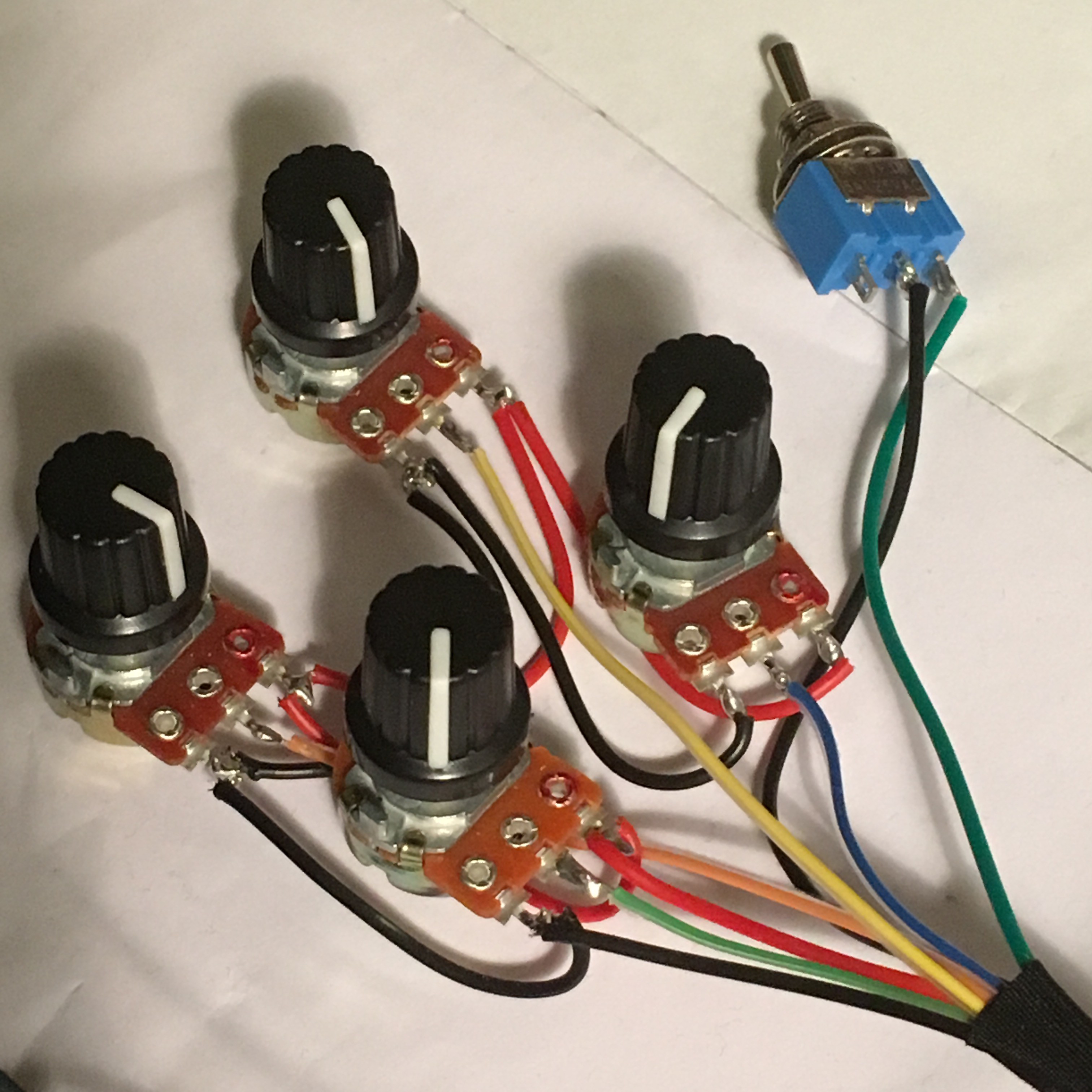
7Step 7
Wire up the potentiometers and the switch (see schematic). Solder the whole assembly to the Teensy.
![]()
-
8Step 8
If the frame was taken apart, now put it back together. Fire up the lasers, aim them at their photoresistor counterparts and fix them with a ring of Sugru around each laser module. Let the Sugru cure for 24 hrs.
-
9Step 9
Power to the Teensy can either be taken from USB, or you can separate VUSB from Vin and use the same power supply as used for the laser assembly. This can be a good idea if you intend to use the harp with DIN MIDI instead of USB MIDI. To use DIN midi, just solder in the optional parts for this according to the schematic.
-
10Step 10
Upload the firmware and have fun playing!
Laser Harp I
Affordable and pretty simple to build framed laser harp using cheap laser pointer modules and a Teensy 3.2
Discussions
Become a Hackaday.io Member
Create an account to leave a comment. Already have an account? Log In.
Great project! Any possibility of velocity sensitivity, or expression parameters that could be added? What libraries and/or #includes are needed? I'd expect a MIDI or something...
Are you sure? yes | no