Isolated probe as an alternative for differential probes
To make the experience fit your profile, pick a username and tell us what interests you.
We found and based on your interests.
asdf_optprobe_design_pack.zipapplication/zip - 17.79 MB - 05/20/2026 at 22:51 |
|
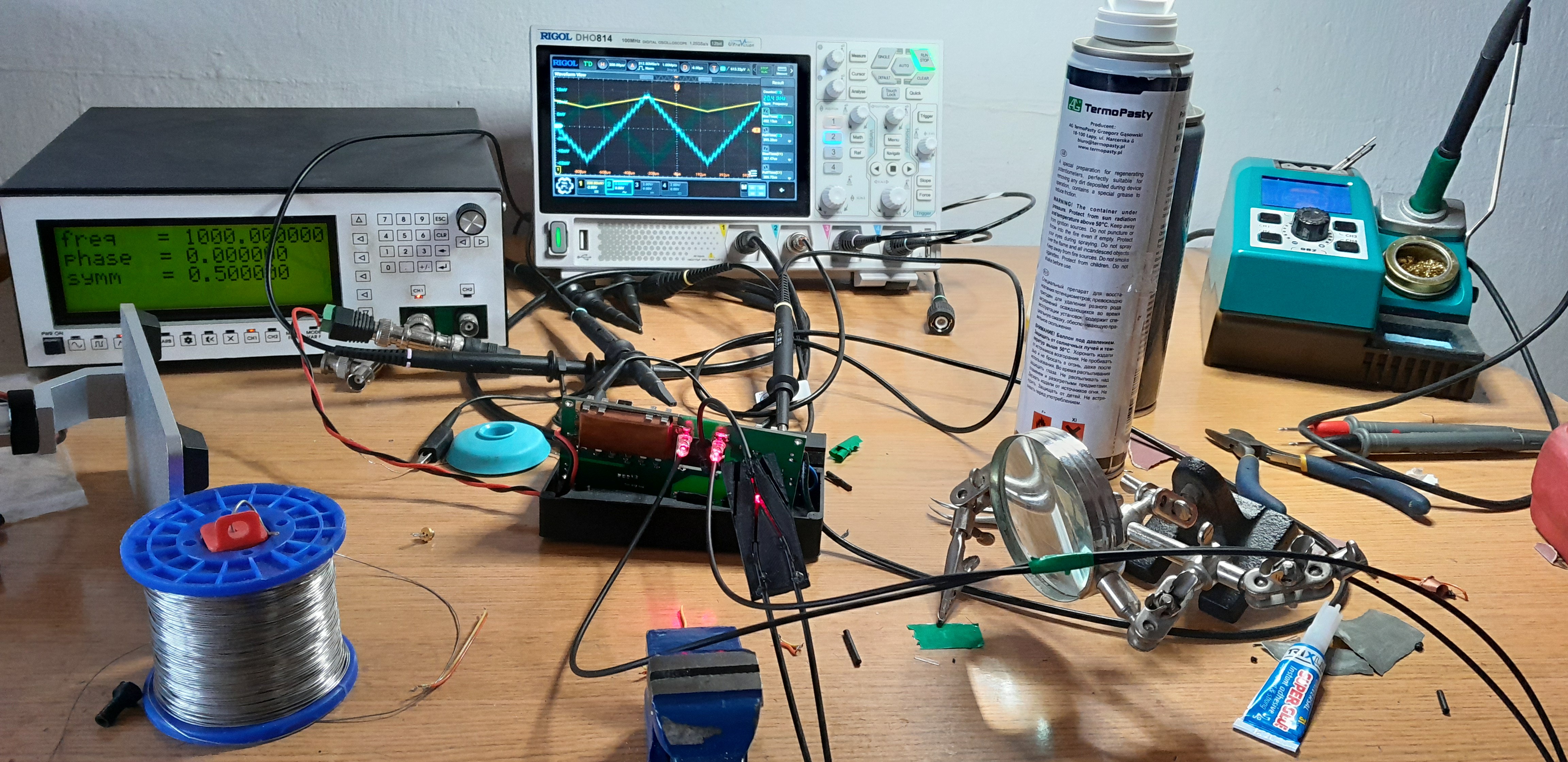
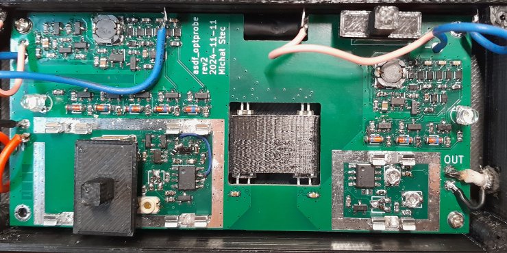
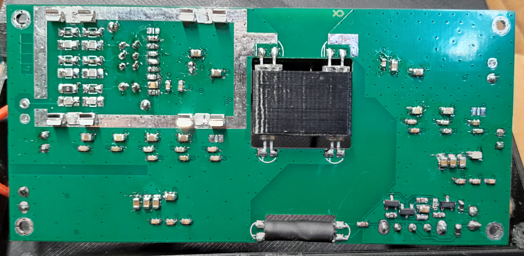
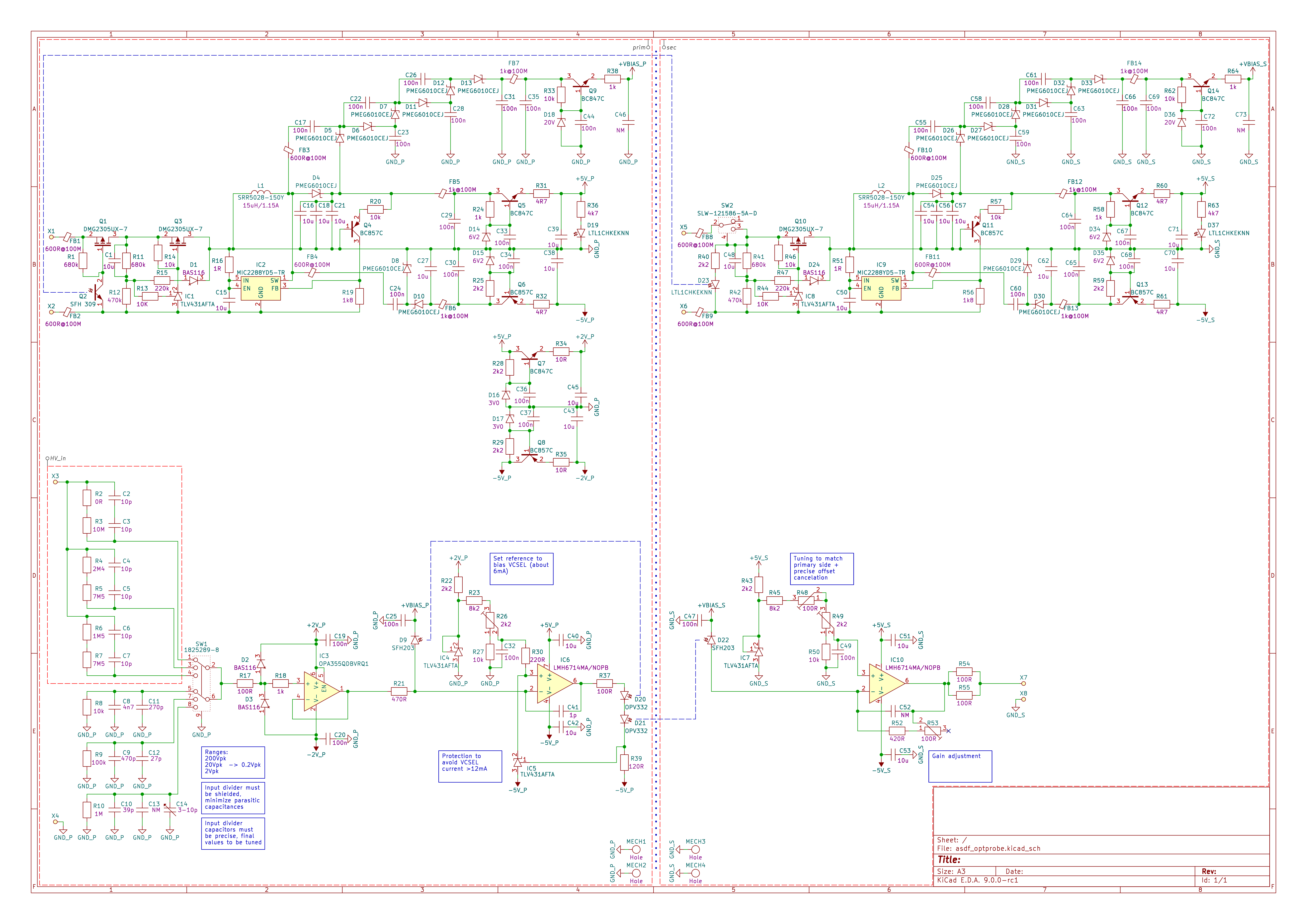
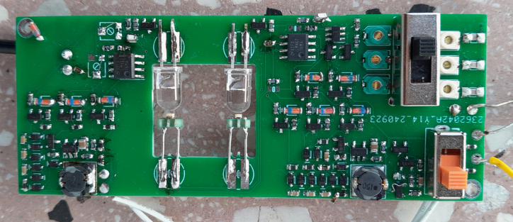
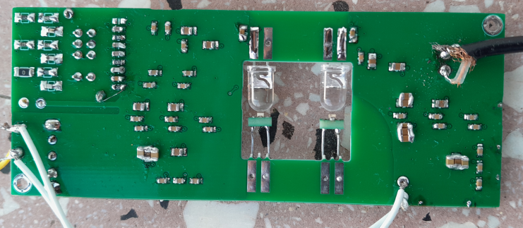
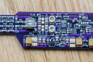
Next revision. The main change is auto-calibration (microcontroller was needed). The main problems in this revision are mechanical construction (poor shielding, light coupling asymmetry and calibration). Still some adjustments maybe needed (LED operating point, maybe different LED, dividers and op-amps compensations, resistors/ferrites in power supply rails), but it works.
Some distortions caused by physics of photodiode were observed, probably unavoidable, but possibly it can be improved by more symmetrical coupling of LED with photodiode. Maybe different LED would be better, but it's hard to find LED with good rise time.
Issue |
Status |
Input divider compensation not accurate As expected, because of parasitic capacitances and poor tolerance, capacitors must be adjusted |
Adjustments (still not perfect): 10x – 33p+6p8 100x – 510p+47p+6p8 1000x - 4n7+470p+68p Maybe better change to a single divider 1/100, then selection of two ranges after buffer |
Instability of op-amp Missing compensation capacitors for the op-amp (recommended by datasheet) |
Added 4p7 on pin for compensation capacitor in receiving op-amp. Not needed for final 10x amplifier. |
Boost converter startup issue Turns off after detecting undervoltage (?) |
Shorted 1R resistors which were added to limit inrush current (maybe unnecessary?) |
Adjustments of optical couplings It’s difficult to match gain in feedback path and primary-secondary signal path. |
Adjustable by screw, but needs better mechanical design. Also, minor flexing of PCB changes coupling while usage (use thicker PCB? different mounting points?). More space for diodes is needed, especially if OPV332 is an option (longer). |
Shielding Not sufficient shielding |
Poor immunity with shielding cans (0.1mm copper), mounted with a few clips to PCB, sealed with copper adhesive tape, SMA-U.FL 1.13mm cable converter. Previous prototype was better, with soldered cans and cables shields soldered to cans, but it was difficult to disassembly and the rigid cables caused bending PCB (causing gain/offset drift). |
Too long calibration Time constants too long |
Change C12: 10u->470n (with PWM 15Hz, it’s enough in detector that drives voltage change for calibration). Change C63: 10u->470n (still good enough filtering of PWM controlling gain adjustment, large impact on calibration speed) |
Possibility of using OPV332 VCSEL |
With OPV332 R40=R61=2k7 R57=0R R58=120R R45=1k8 C46=2p2 C56=3p3 Advantage – higher bandwidth (-3dB at about 30MHz, with LED about 15MHz). Disadvantage: noise is high – about 7mVrms, 70mVpp in 20MHz, above 10mVrms without bandwidth limit, also depending of diode bias (at 1V range, so the noise is a few percent of full range – quite noticeable). |
Possibility of optimizations with VSLY3943 LED |
Consider adding capacitors to resistors limiting LED current, to speed up at higher frequency: R57=47R||220p R58=22R||220p Then reduce capacitor in feedback of op-amp (which reduces ringing and is needed for stability): C46=2p2 On receiving side it can be: C56=4p7 Move up slightly current of LEDs: R40=R61=6k2 R45=620R R69=15k VSLY3943 has less noise than OPV332, about 2mVrms 13mVpp in 20MHz, bandwidth is about 15MHz, some DC offset appears at high frequency (asymmetry of rise and fall time), some nonlinearity – at +1V and -1V it’s about 2% difference (when 0V has no offset). |
Distortions of signal with VSLY3943 Square wave is not quite square, first it’s a fast rise time (about 20ns) to almost final voltage, but then it takes some microseconds to reach the final voltage. |
The problem is observed also in a separate test of diode-photodiode,... |
Next version.
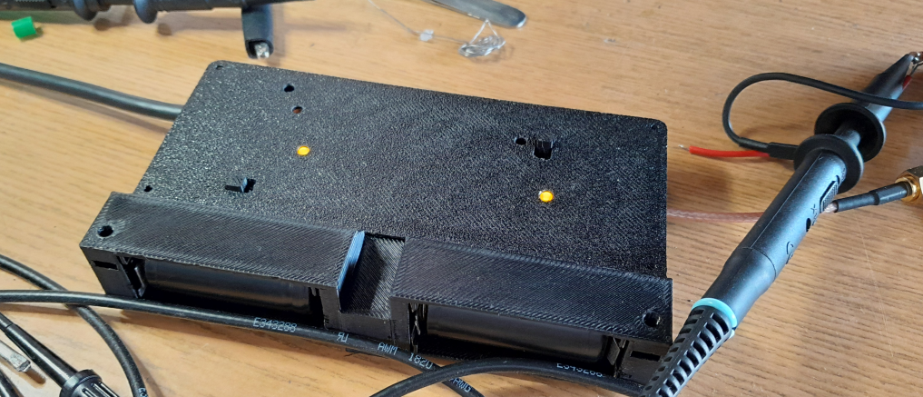
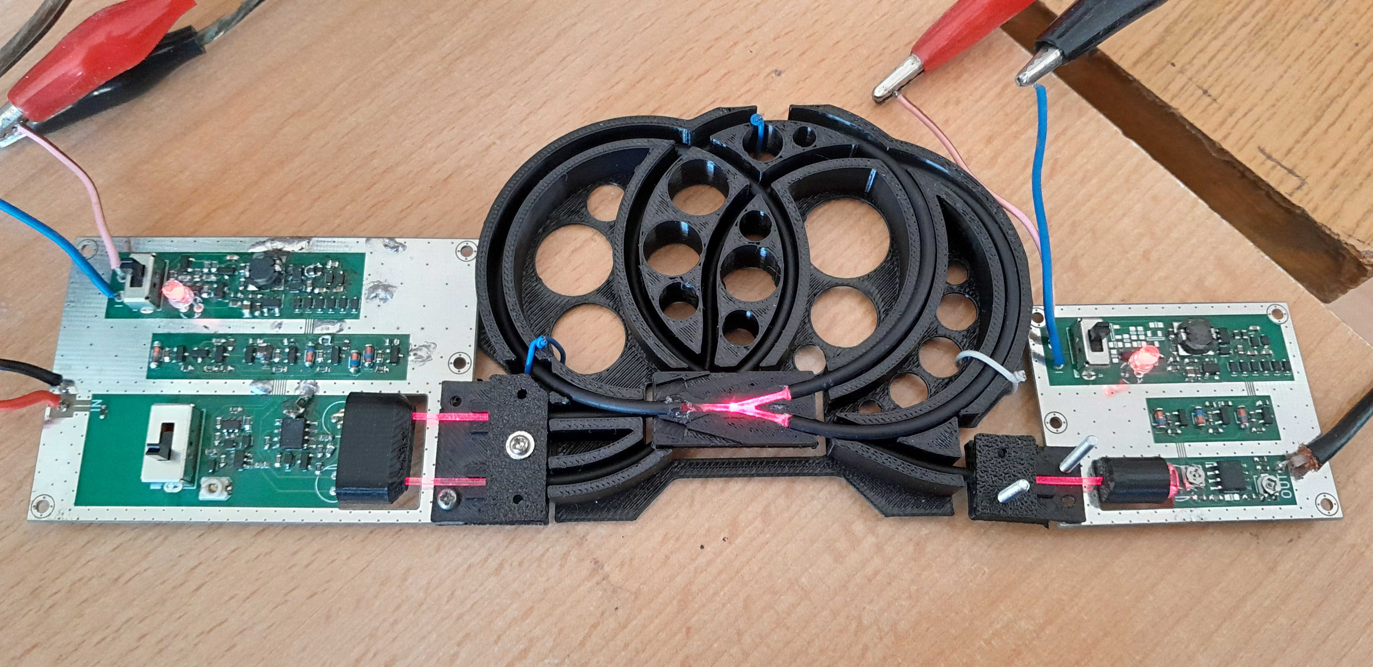
In contrary to the version with laser and plastic fibers, transmitter and receiver are in the same enclosure for stable transmission through light-pipe.
In contrary to the first versions, there's no mechanical symmetry of couplings between IR transmitter and photo-diode in feedback path and primary-secondary path. In feedback path the LED and photo-diode are near, to keep tracks to op-amp short. In primary-secondary path, plastic light-pipe is used to provide optical coupling and isolation distance (MENTOR 1216.1003). It works well, but coupling in primary path must be slightly reduced for symmetry.
Shielding is very important (details below). In the prototype, about 40mV (or a bit less with bandwidth limit in oscilloscope 20MHz) was achieved when 4kV burst disturbance was connected to input ground (coaxial short connected), which is 4% of full scale.
Issue |
Status |
Input divider compensation not accurate As expected, because of parasitic capacitances and poor tolerance, capacitors must be adjusted. |
C4 change 39pF to 33pF C3 add parallel 47pF+4.7pF C12 add parallel 150pF The values can’t be frozen yet because poor tolerance parts were used in the prototype. |
Instability of op-amp loaded with IR emitter The op-amp oscillates with initial values of components at the output. |
Increasing resistance in series with the IR LED fixes the problem. R46 changed from 0R to 47R. |
Boost converter startup issue MCP1640BT fails to start if it’s loaded by TPS563209 too early. |
Doesn’t start every time. Soft-start (RC at enable input of TPS563209) partially fixes the problem but it’s still not reliable. Other boost converter may work better (to be tested). |
Ringing Frequency response is not perfect, there’s some overshoot and ringing seen on square wave. |
Added 4p7 in place of C46 – it’s trade-off between ringing and bandwidth (it’s about 15MHz). |
Calibration reliability Gain and offset must be calibrated before using, after warm-up, using two SMD potentiometers. It’s not very reliable |
No change. For future, consider designing auto-calibration. |
Input divider optimization Simplify, miniaturize. |
No change. For future, consider using smaller parts, as the max input voltage is only 100V. |
Adjustments of optical couplings It’s difficult to match gain in feedback path and primary-secondary signal path. |
Blocking light with some dirt on lens or a piece of tape. For future, design something better, preferably adjustable by some screw. |
Shielding It’s critical to shield very well. Vulnerability to EM disturbances defeats purpose of the project. |
Copper cans soldered on top and bottom of the transmitter and receiver circuits. Primary side cable connection changed to avoid unshielded signal conductor (PCB redesign needed). Critical points: 1. Input divider. High impedance nets with low signals. Hole for the switch handle and compensation trimmer are big issues. Additional copper cover (moving with the switch) was added (covering lever from all sides). 2. Receiver photo-diode. The structure is too close to the opening in shielding can. Adding some copper foil wrapped around light-pipe redirect the field from primary side to the shielding can. 3. Connectors and coaxial cables – they will catch noise is there’s poor shielding or connection of shield. |
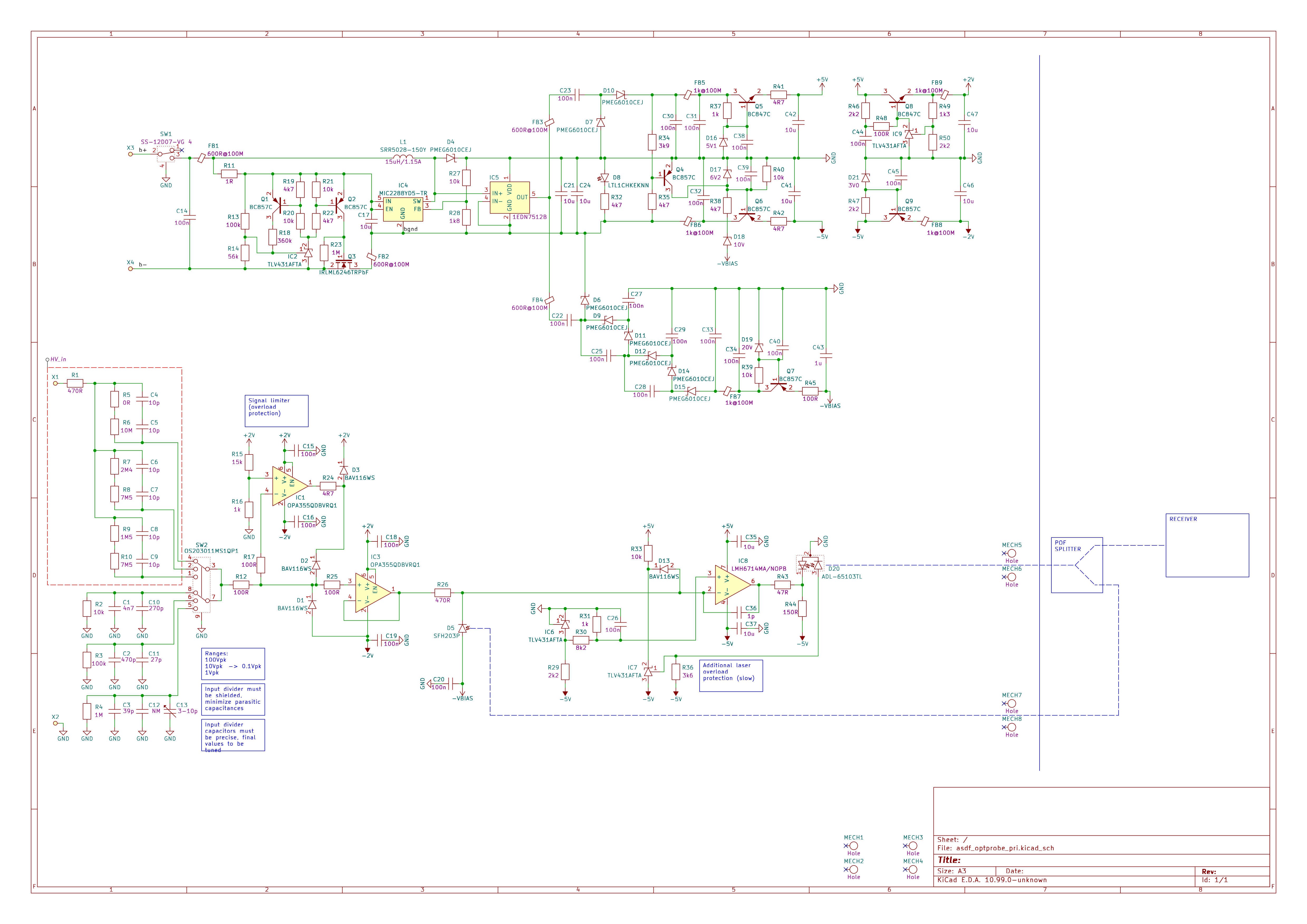
I tried to make separate transmitter and receiver, connected with 1mm plastic fiber. I used a laser diode ADL-65103TL and similar photodiodes (SFH203P - flat front).
The main problem was that the plastic laser losses change when bending/touching, causing gain and offset errors and coupling fiber to laser required some precision (even if it's 1mm fiber, losses are very sensitive to small movements).
Because of that, both transmitter and receiver were finally placed in the same enclosure. Some loops of fiber were added to scramble the light a bit (not sure if it helps). The mechanical construction was too complicated and I gave up with future works (a lot of plastic elements, hand-made fiber splitter). Protection of laser diodes added some complication to the electronics too.
Next time I'll use IR diodes instead of laser again and light-pipe to couple transmitter with received instead of fiber.
On the electronics side, some issues in this version:
Issue |
Status |
UVLO still unstable (not sufficiently tested yet) |
To be redesigned. Secondary side not assembled or tested yet. |
Discontinuous mode and charge pumps With too light load (on secondary side), discontinuous mode may be not the best for operation of voltage multipliers. |
But it works... |
Power supply issues (primary) (not sufficiently tested yet) |
R34 temporary changed from 3k9 to 2k5. FB3 temporary shorted. Maybe some issues were caused be unstable load. C44 removed because it caused instability. |
Instability of the amplifier driving the laser It caused distortions, jumps of amplitude/offset (e.g. sudden change after warm up) |
It was observed with spectrum analyzer that oscillation occurs at 650MHz. To fix, RC circuit 220pF+22R was added between the amplifier output and ground, C36 about 4.7pF. The issue may be dependent of length of fiber in feedback path. |
It seems that photodiodes must be well shielded, but separated electrically. In rev1 and rev2 the diodes are outside of shields to make it easier to couple them optically and keep symmetry.
This doesn't work well because of too high noise susceptibility. In future, probably one photodiode will be coupled with the emitter with a piece of lightpipe. This arrangement will be not symmetric, so maybe some mechanical adjustment of coupling between emitter and photodiode will be needed to not worsen linearity.
Also I did some test with laser and 1mm plastic fibers. For these fibers, 650nm (red) light is suitable (not infrared). There are some difficulties:
- Too little signal - I use 5mW laser. More powerful lasers are available, but I'd like to avoid too powerful laser because of high price and safety concerns. It works, bandwidth is OK, but even if the laser touches photodiode, the output signal is weak.
- Instead of two emitters, one emitter should be used, because it may be hard to ensure that operating point of two lasers are equal (they are very sensitive to temperature and must be modulate by small changes of high DC current), so the light must be split.
- I couldn't find suitable light splitters for 1mm plastic fibers, so I've made one. It has high losses and bad symmetry, but it may be enough for the purpose (some mechanical tuning will be needed to ensure both diodes get the same light).
- There are high losses in the splitter and also at lase/fiber coupling and fiber/photodiode coupling. To reduce the losses, the fiber end should be polished (I used 2000 sandpaper), and adding some fluid at the point of connection helps a lot (I used isopropanol to see the effect, but maybe some transparent oil or glue will be suitable for permanent effect).
Revision 2 is made on 4 layers board and has some shielding to improve noise immunity. Low frequency noise immunity is good but immunity to high frequency noise is still not perfect. Photodiodes were initially not shielded so I had to wrap them in a copper foil to improve immunity. There's still some work to do, to minimize the susceptibility - it's not easy, because the signal is in milivolts range and the device may work near noisy equipment. Possibly a different construction, with very good shielding, including photodiodes, will be needed.
In this revision OPV332 VCSEL emitters were used. Unfortunately they are not perfect - they are usable in small range of power, but with higher power the noise and non-linearity is too bad (the nonlinearity seems "unstable", sawtooth is "wavy" and its shape is easily changed by touching the optical assembly or by small changes of input signal). I don't know reasons of the weird nonlinearity (is it only VCSEL property, or it's more a problem of interaction with photodiode?).
Possibly two versions can be considered in future:
- variant with VSLY3943 LED emitters - linearity is good, bandwidth limited below 10MHz
- variant with OPV332 VCSEL emitters - bandwidth over 30MHz, worse linearity and noise
Issue |
Status |
Resonance of input wires A lot of ringing is visible at fast edges. This could be expected and can be reproduced in simulation. Inductance of wires for signal input (hundreds of nH) resonates with input capacitors (about 5pF). |
Add 470R resistor in series with input to prevent resonance of the wires with the input capacitance. This 470R is small enough to not cut usable bandwidth. |
Bias of TLV431 for laser overload protection The TLV431 connected directly to the non‑inverting input of the op‑amp changed operating point so that it doesn’t match the secondary side op‑amp. |
The TLV431 should have cathode pulled up to positive voltage and be connected through diode to the non‑inverting input of the op‑amp (the diode is not conducting during normal operation). |
Voltage drop on photodiode bias There’s a noticeable voltage drop on a 1k resistor at the output of power supply bias output. |
Change the resistor to 100R. (maybe consider replacing with ferrite, also test if larger filtering capacitor is needed). |
No clean turn-off when battery is low Slow falling edge at the output of the MOSFET doesn’t turn off TLV431 immediately, also battery voltage increases when MOSFET turns off |
To be done: try tuning, maybe add more transistors, detect falling edge, further complicate the design |
Distortion at some voltage level Weird distortions observed when OPV331 laser diode was used. Decreasing photodiode current (by decreasing laser current or blocking some light) makes the distortions lower (it also lowers noise). |
Maybe two versions are to be considered: - OPV331 – high speed, worse linearity, bias optimized to lower distortions and noise (low photodiode current, low input amplitude) - VSLY3943 (alternatively VSMY5850 +external lens*) – low speed, high linearity, larger overshoot because of delay in feedback loop (compensating capacitor can be selected to decrease overshoot or increase bandwidth) - VSLY3943 – R27=1k6, R39=0R, R37=100R, C41=2p2 (To be done: optimize R37, R39, maybe R21**) - OPV331 – R27=?, R39=120R, R37=100R, C41=NA (To be done: optimize R27, test different R21, maybe change input divider or range) * VSMY5850 has lower wavelength (should be good for response time) but nominal response time is lower, it’s SMD and external lens may be needed, possibly slightly better (more tests needed…) ** If emitter is slow, R21 could be increased (slower detector might be not an issue) – tested change from 470R to... |
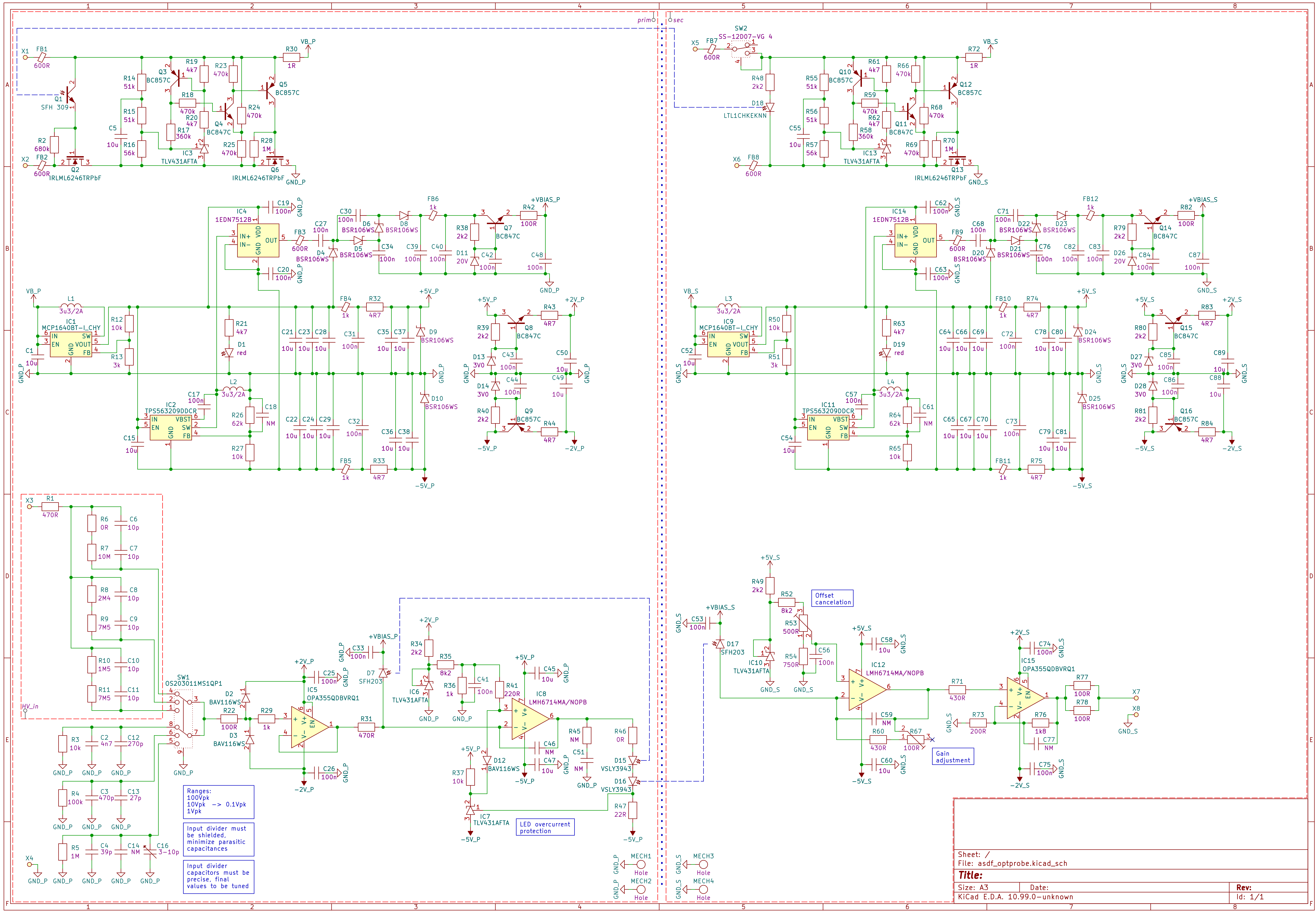
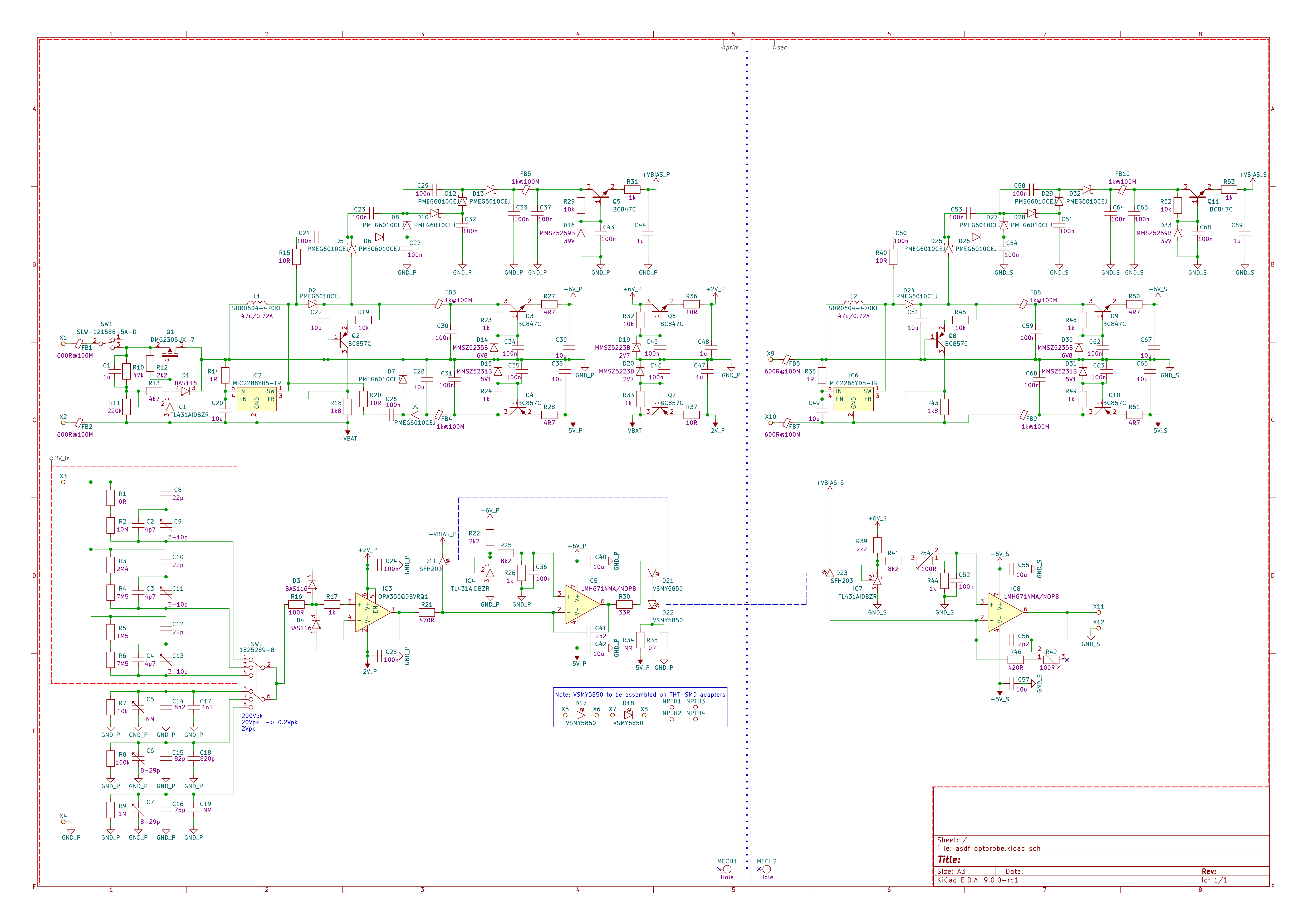
The primary side consists of: power supply, input signal divider (1/10, 1/100, 1/1000), low input capacitance buffer and operational amplifier that drives IR emitters. Feedback of the amplifier includes additional IR emitter and photodiode (the same as on the secondary side) - it's needed for linearization of characteristics of the emitter and detector.
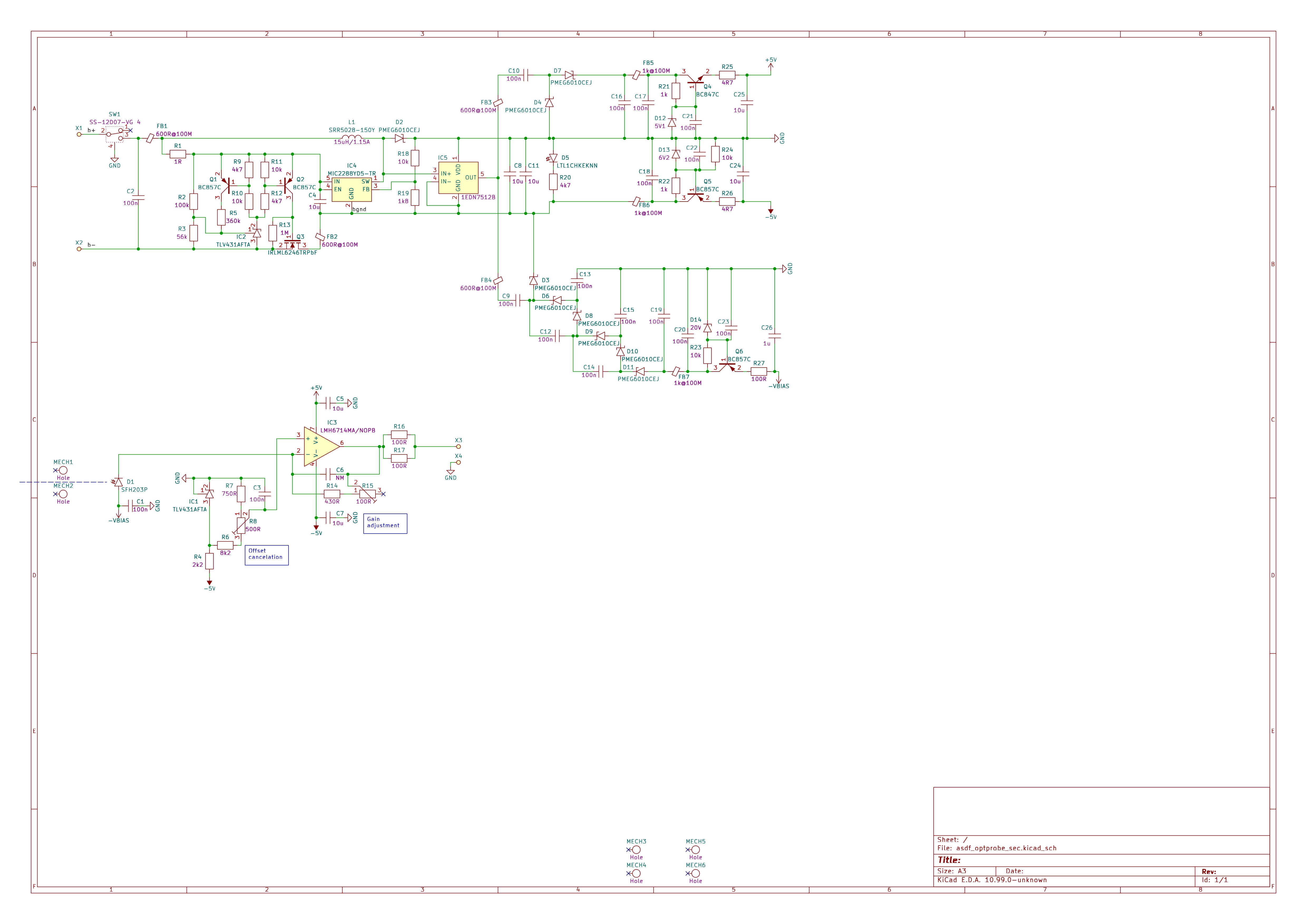
The secondary side consists of: power supply and amplifier that converts photodiode current to the output voltage.
If emitters and detectors have similar characteristics (preferably they are paired), then voltage on R21 and (R42+R46) should be identical (good linearity).
The main problems with the first revision was susceptibility to electromagnetic disturbances: switching noise from internal converters and external SMPSs, also picking up low frequency noise by input voltage divider. Also there were some issues with power supplies or other design issues.
Initially, the infrared emitter was LED, then I started testing VCSEL. VCSEL provided more power at lower current and it was much faster (about 40MHz achieved with VCSEL, with LED it was only about 10MHz). The used VCSEL could be easily overloaded so some active protection was needed in next revision.
Issue |
Status |
Can’t turn on. Under-voltage battery protection issue. Q1 doesn’t turn on after closing the switch. It can turn on if C1 is increased from 1u to 10u. R13 can be increased too. |
C1 and resistances are increased. Larger time constant is needed because it takes time to start the boost converter. |
Power not delivered at low battery voltage. Under-voltage battery protection issue. Q1 doesn’t fully turn on if input voltage is low (about 3.4V). Voltage is too low for TL431 so it’s unable to properly bias gate of Q1. |
TL431 (Vref=2.495V) replaced by TLV431AFTA (Vref=1.24V). The same reference will be used in other places of the circuit. New resistors values for TLV431AFTA were selected. |
Unstable step-up converter. As datasheet suggests, low inductance and high output capacitance is good for stability. L1 and L2 15uH, C2 and C51 3x10uF works OK. |
Tested with #A920CY-150M=P3 (15uH) and output capacitors 3x10u works well. A sililar SRR5028-150Ycan be used instead. The used inductors are magnetically shielded to minimize noise. |
Noisy power supply. Resistors were added at inputs of charge pumps (R15, R20, R40) but they are not enough. Replacing then with ferrite beads helps (1k@100MHz used but it’s maybe too much). |
Added ferrite beads at inputs of charge pumps 600R@100MHz. |
No signal - saturation. Incorrect bias for the used emitter+photodiode (VSMY5850 and SFH203). R26 and R44 had to be much lower because VSMY5850 can’t cause that much current through SFH203. |
VSMY5850 won’t be used, bias should be designed for IR emitter OPV332. Potentiometers were added to make it adjustable (OPV332+SFH203 may be not very repeatable). Tests shown that 0.7V at “+” input is good for range and linearity (so about 1.5mA through photodiode should flow at 0V input) – voltage divider was adjusted. |
Could be faster. Emitter VSMY5850 and photodiode SFH203 were good up to about 10MHz, C41 was required to avoid ringing. OPV332 (VCSEL) instead of VSMY5850 (LED) works better: - higher signal (0.4Vpp at output), - wider bandwidth (probably 30MHz), - lower current - less heating, so better thermal stability expected (10mA is max, now limited to 5mA). - THT package (not SMD-THT adapter required) Higher cost but it’s worth the money. R30 is changed from 33R to 220R. C41 not placed. |
VSMY5850 was changed to OPV332. Cathode must be connected to -5V (not GND) to ensure voltage sufficient for bias (considering op-amp output range and max voltage drop at OPV332). Op-amp output... |
Create an account to leave a comment. Already have an account? Log In.
Become a member to follow this project and never miss any updates
Bud Bennett
Burkhard Kainka
Evangelos Petrongonas