 mircemk
Earthquakes are extremely common events around the world. On average, there are fifty earthquakes a day, around twenty thousand a year. Many are mild and go unnoticed, but some are catastrophic. It is not always possible to predict when a disastrous event will occur. Using special sensos, designers can make their systems safer and minimise the risk of secondary damage from earthquakes by safely shutting down critical devices and halting their operation. In this project I will describe a device that uses this type of sensor.
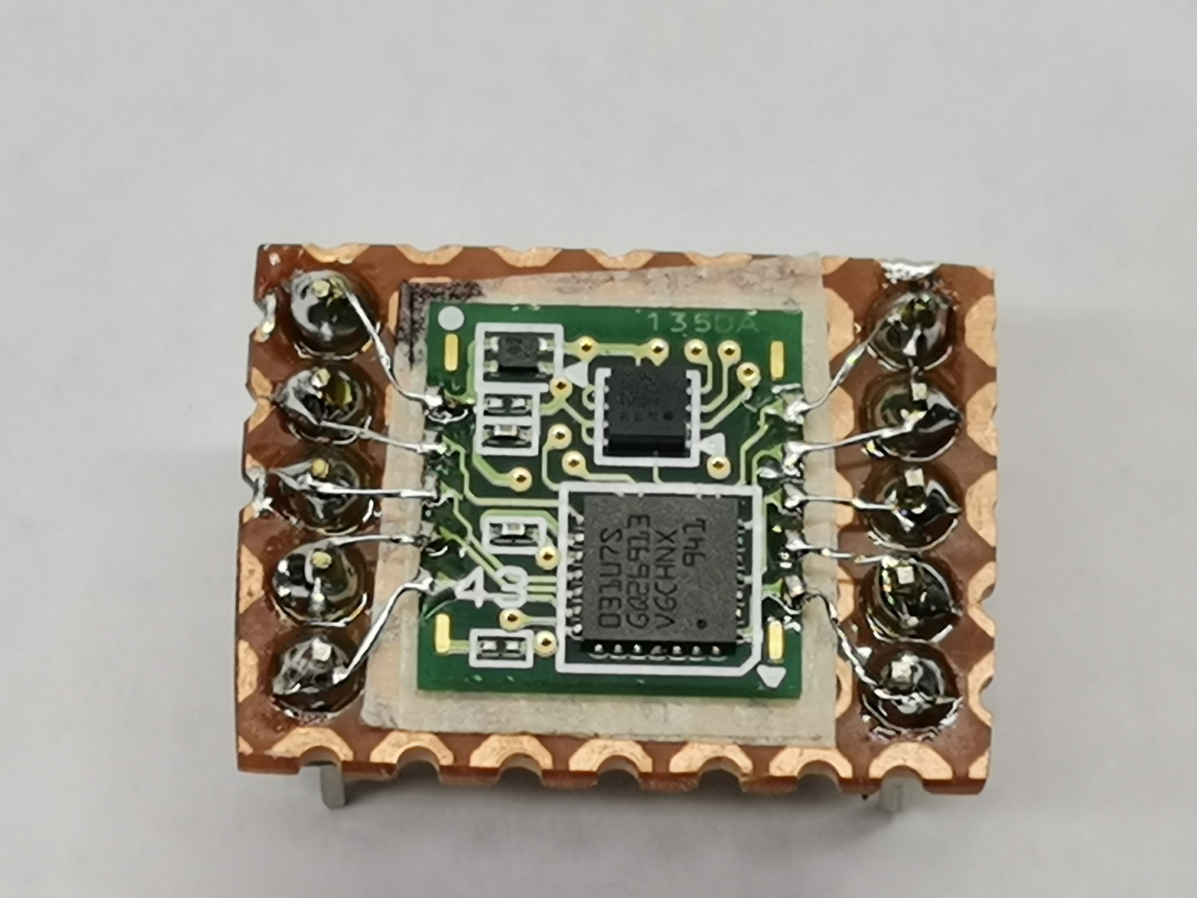
Specifically, the sensor I am using is an Omron product and its designation is D7S. A key feature of the sensor is its ability to distinguish between actual seismic activity due to an earthquake and signals due to other causes. When an event occurs, the D7S uses unique Spectral Intensity (SI) calculation algorithm to distinguish between seismic activity and other types of motion. The sensor includes a three-axis accelerometer that can take measurements to calculate the SI (spectral intensity) value and determine the magnitude of the earthquake. Spectral intensity (SI) correlates highly with damage to structures. These facts are the biggest difference between this sensor and, for example, the MPU6050, which, by the way, reacts equally to all types of shocks and vibrations generated from various sources.
And first of all, let me clarify that this sensor is not intendet and sensitive enough to make a seismometer, but its main purpose is to turn off a device during a strong earthquake, which would reduce the damage caused. For example, during a major earthquake, the gas supply to a certain building would be turned off because there is a risk of its collapse, or the power lines would be turned off. To control and read the data from the sensor, I use an Arduino Nano microcontroller board and the appropriate library.
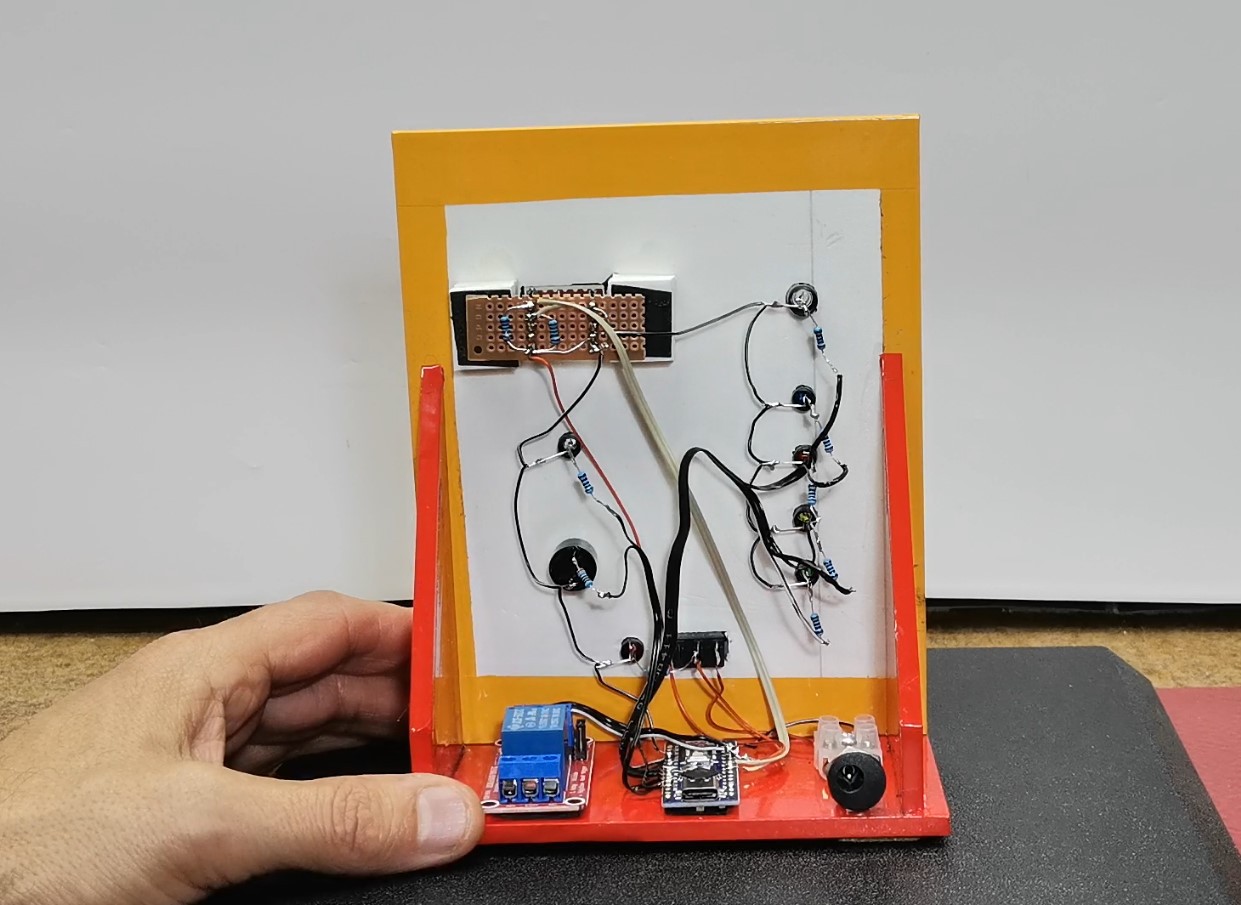
As you can see, the device is very simple and consists of several components.
- Omron D7S seismic sensor
- Arduino Nano microcontroller board
- Buzzer
- 6 Leds with apropriate current limitin resistors
- and optionally small 5V relay module
This project is sponsored by PCBWay. This year, PCBWayorganizes the Seventh Project Design Contest where, in addition to Electronic and Mechanical Project, also has been added a new category: STM32 Project. For the best selected projects are provided rich prizes in cash, coupons and special gifts. Submit your project for participation in this Contest from 2nd, Sep, 2024 to 19th, Jan, 2025. For more details and instructions visit the given page. Let PCBwayalways be your first choice

The code is based on Alessandro Pasqualini's excellent library, in fact, in one of the examples I added LEDs and a buzzer for signaling and a relay module for controlling other devices.
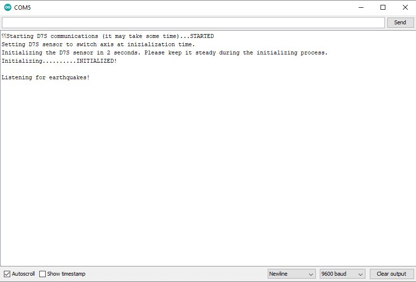
First, let me explain how the device works. After turning it on, we need to wait a certain amount of time, during which communication and initialization of the sensor are established. During that time, the device should be in a state of complete standstill. Then the white LED lights up, which is a sign that the device is ready to react to a possible shock. We can also observe this startup process on the serial monitor if we connect the Arduino to a PC.
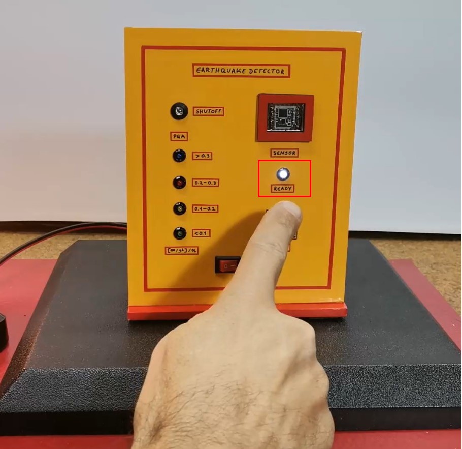
These 4 LEDs are for indication of a possible earthquake. The intensity of the movement is displayed in units of PGA (peak ground acceleration) and is expressed in m/sec^2. Peak Ground Acceleration represents the intensity of the shaking at a specific point on the Earth's surface. It is used to assess the potential for earthquake damage to structures and is particularly relevant for engineering and construction, as buildings and infrastructure are designed to withstand certain accelerations. It is interesting to mention that this sensor has its own memory where it stores previous events. In this case, is displayed the strongest earthquake intensity that occurred in...
Read more »

 Matthias Kampa
 Krishna Mohan
 Vignesh Ravichandran