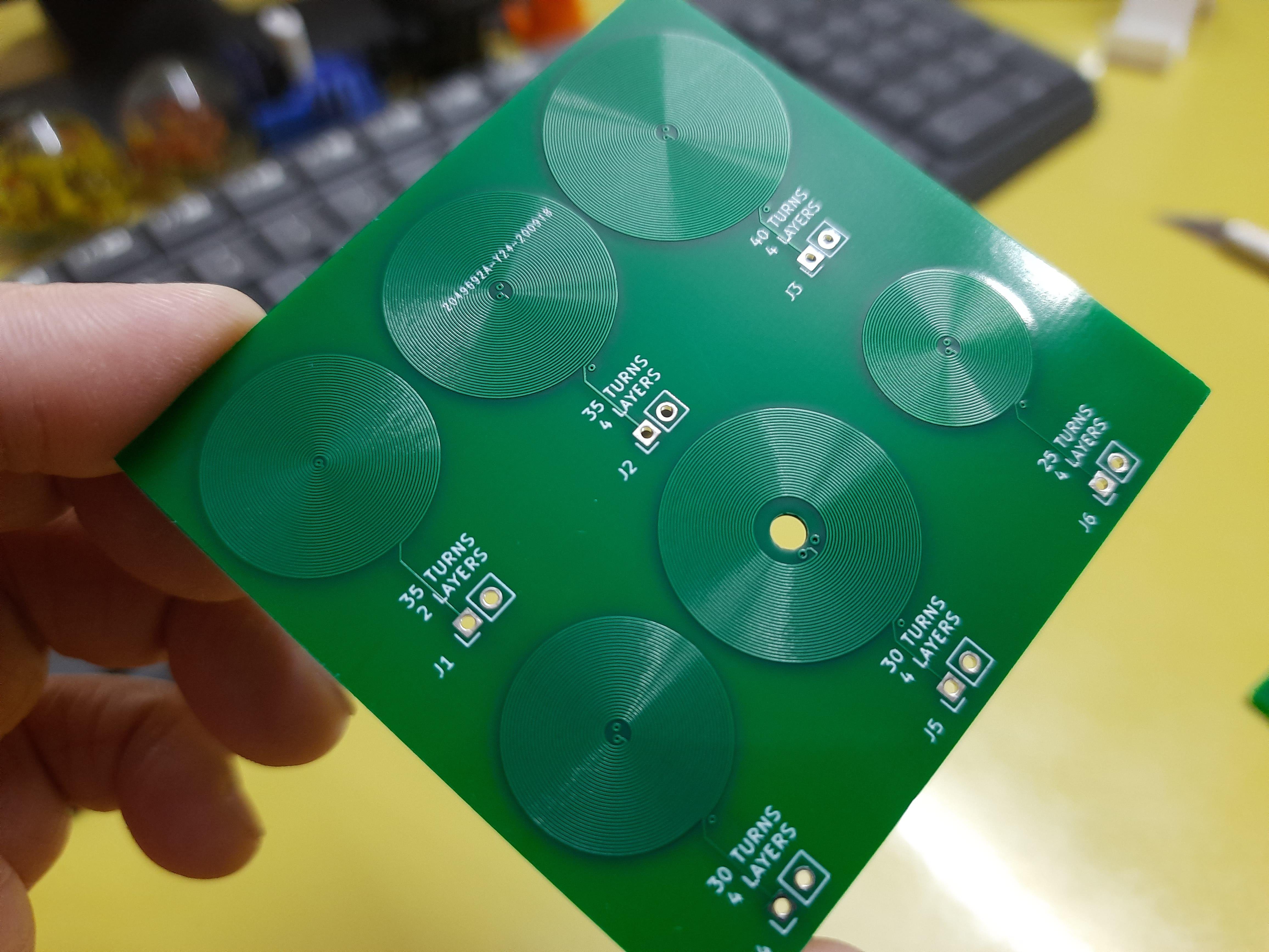
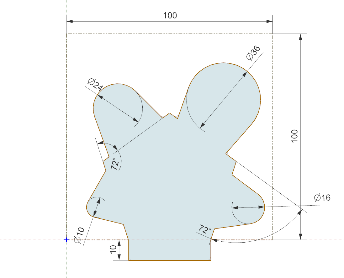
• Project Log 1 - Initial Development PCB

    colton.baldridge04/26/2025 at 20:23 0 comments

    Picking up where I left off in the last project log, I began working with the idea that I could use PCB coils to generate a magnetic field that could be used to flip a dot. I already had some experience with PCB coils from my OS3M Mouse project, so I knew the theory was sound and that my fab house of choice (JLC) could create the hardware. 

    (generic PCB coil image, not mine)

    So I set to brainstorming some ideas. How could I get the magnetic field from the coils to the magnetic dot? How many coil turns do I need? How much current do I need? How many layers should the PCB be? As I thought more, I came to the realization that I needed to buy down some risk. I needed to create a dev board, before jumping into making a full array. So I set to work: I needed a board that would tell me the following:

    • What is the minimum number of turns I can get away with (determines coil size and thus flip dot pixel "pitch")
    • How many layers do I need (strong driver of PCB cost)
    • How much current will I need to flip the dot (determines heat load on the coil, drives framerate of the display, also informs driver selection)
    • What does the mechanical structure need to look like to transfer magnetic flux from the coils to the flippable dot (general project risk)
    • Can this even work at all? 

    So I set to work designing a board that would allow me to answer these questions and more. I started by breaking out my trusty PCB coil designer script, but it needed a bit of modification. I added features to support more than 2 layers, a center drill hole, and added some features to make breaking out the layers a bit simpler. (commit coming soon). I then decided (somewhat arbitrarily) that I would like to test 10, 20, 30, and 50 turns, as those made reasonably sized coils at JLC's minimum recommended trace width and spacing (0.15mm). I also decided on 16AWG galvanized steel wire to be my "core" material that would transfer my flux to the magnet in the dot. I did this because steel (low carbon) has decently high permeability, and it was cheaply available at my local Home Depot. I want this to be cheaply and readily available to anyone who wants to build one, which means custom ferrite cores (like what is used by real flip dots, I believe) are off the table. I then began the process of mechanical and electrical codesign. I laid out an outline of a board in my CAD suite, where each coil was a protrusion on a side of the pentagon, and one last side was to be used as the interface. 

    The reasoning for this shape was so that I could place any 2 coils side by side, and then put metal in a ‘U’ shape between them. That would allow me to build flipdots of varying coil size without much modification of the flipdot’s mechanicals, and all I would have to do is swap connections on the pin headers to the new coils. 

    I also wanted to try out some drivers for the dots, so I integrated 4 into each dev board. These drivers needed to be CHEAP, as I am gonna need hundreds of them. Thankfully, driving a PCB coil is basically the same as driving a little DC brushed motor. This means I can leverage the wide selection of VERY cheap DC motor drivers on LCSC. The one I chose was the TC8301, which has a datasheet almost entirely in Chinese, but thanks to Google translate, I was able to discern the key parameters:

    • VCC_max = 7.2V
    • P_max = 0.96W
    • RDS_on = 1.6ohms
    • I_max = 2.5A (no time limit given)
    • I_cont = 1.5A

    This little chip is only THREE CENTS so it should be a perfect candidate for use in the big array. Down the road, to further save on cost and board space, I’d like to multiplex the array so I only have to have drivers for each column/row rather than for each dot.

    With all this in mind, I cracked open Kicad and designed it. I hadn't worked with Kicad in a while, so while I remember the fundamentals of PCB design, the mechanics of it were a bit clunky. I wanted to recommend this video to anyone else in my position. It covers all you really...

    Read more »

  • Project Log 0 - Preface and Previous Experiments

    colton.baldridge01/07/2025 at 07:49 0 comments

    I have been enamored with flip dots ever since I first found out about them. They are these unique electromechanical marvels that, to me, seem primitive yet elegant. It makes using modern screens with "pixels" seem like cheating in a weird solid state way. I think it's something similar to the feeling that people who enjoy tube amplifiers get, where they know they're using something technologically inferior but it has this "cool" factor that justifies the increased cost/power/space. To that end, I have wanted a flip dot display of my own for quite a while. Something that is both beautiful as wall art, and useful as an information display. 

    I started out by seeing what was already out there, and to be honest, there isn't much. Almost all projects I've seen videos on utilize second hand screens pulled out of busses or airports or whatnot. Or, alternatively, corporations who have the cash are buying large displays from a vendor new. Being a maker, I scoured eBay looking for any deals on used displays but to my dismay, there really weren't any. The best I found was this bus display for $425 that is only 30 * 7 pixels. 

    This was not what I was looking for. To set out the first 3 requirements of my project, I wanted (1) to build a display approx 1.2m * 0.7m to fill up my wall, (2) to cost less than $300 (BOM cost), and (3) to utilize efficient and reasonably accessible production techniques available to the everyday maker (3D printer, JLCPCB). I also want to make things a bit... unusual and do something I haven't seen anyone else do - flip hexagons, or fliphexes for short (because we all know hexagons are the bestagons). And with these in mind, I set off on my design process.

    To get a lay of the land, I initially looked into how commercial displays are constructed. They look to be made of an injection molded plastic piece with a flippable dot dangling between two posts at the top. Below there is a U-shaped iron core with tons of copper windings wound around it to create a magnetic field that then interacts with a magnet in the dot to do the actual flipping. I'm really not sure how they make these things in a cost-effective and highly automated fashion. I cannot find any videos online as to how they do it. Here's an image showing the general idea of how they're constructed:

    I started mulling about how I would make my own dots. Would I try to build a machine to make them exactly like how existing ones are currently made? That seems challenging to say the least, as they likely have some precision winding and soldering machine to do it for them that took a lot of time and money to build. The real challenge is going to be the copper wire - specifically attaching the copper wire to the drive PCBA. I looked around for surface mount or through-hole electromagnets, but they don't exist (and why would they?), but then I was struck with an idea. What about inductors? They're just big electromagnets. I learned there are actually 2 types of inductors, shielded, where the core material extends all the way around the coils to keep the flux contained, and unshielded, where the flux flows through air for some portion of its trip. This makes unshielded inductors an interesting potential candidate for my use case, so I whipped up a Digikey order to try things out and got to CAD modelling. I came up with this:

    The first fliphex. You can see the two through-hole, unshielded inductors acting as electromagnets to push/pull the magnet in the hex. This design actually worked! See video below

    But... this prototype has several issues that ended up making this a non-starter for a big array. In no particular order:

    • The inductors are too large for the magnetic field they deliver
    • The inductors are WAY too expensive to make a big array out of
    • The inductors are finicky with their position, and do not have a clear +/- labeling on them, meaning if I wanted to assemble an array and not do tons of software work, I would have to manually...
    Read more »