-
Project Log 0 - Preface and Previous Experiments
01/07/2025 at 07:49 • 0 commentsI have been enamored with flip dots ever since I first found out about them. They are these unique electromechanical marvels that, to me, seem primitive yet elegant. It makes using modern screens with "pixels" seem like cheating in a weird solid state way. I think it's something similar to the feeling that people who enjoy tube amplifiers get, where they know they're using something technologically inferior but it has this "cool" factor that justifies the increased cost/power/space. To that end, I have wanted a flip dot display of my own for quite a while. Something that is both beautiful as wall art, and useful as an information display.
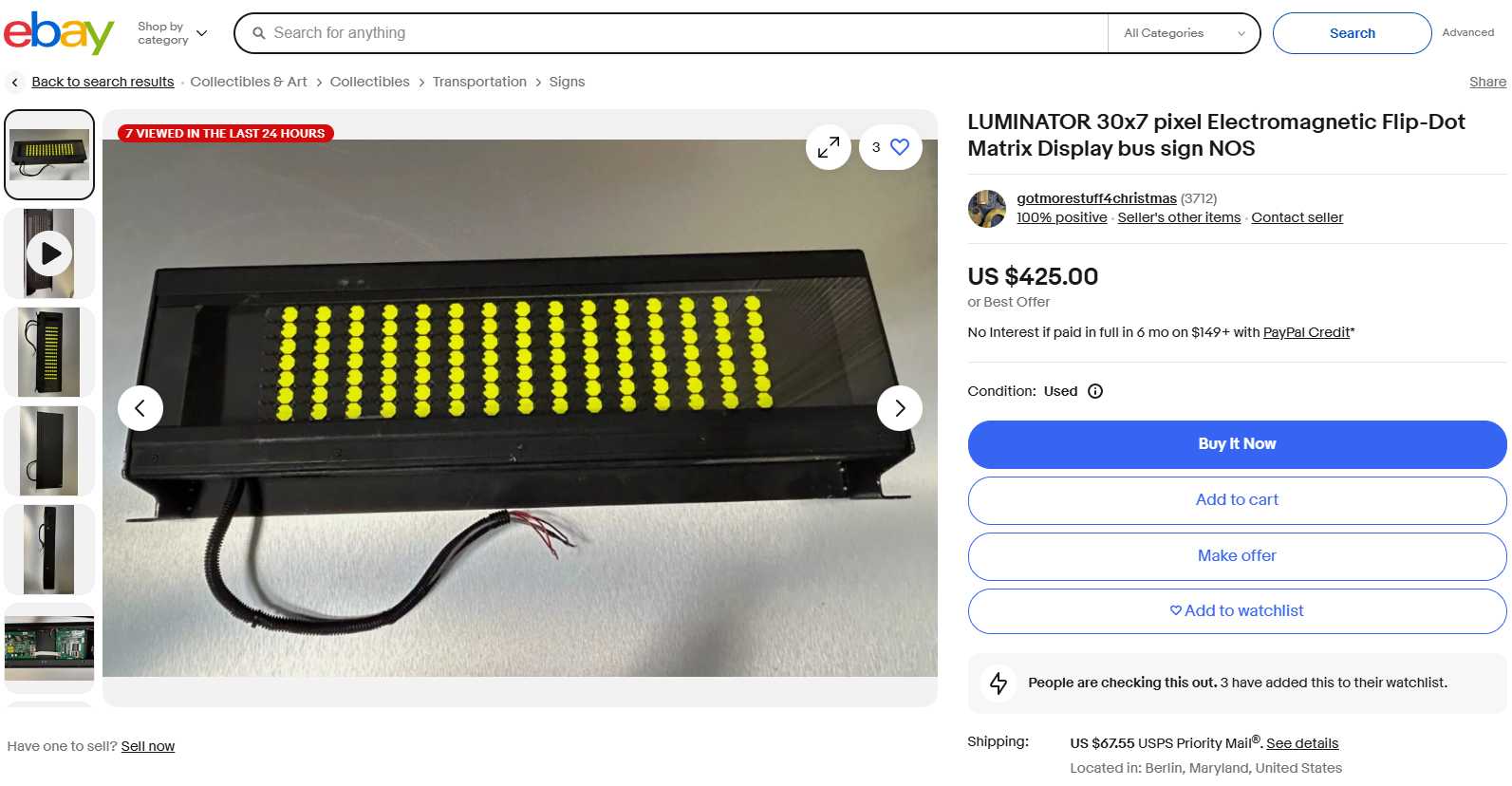
I started out by seeing what was already out there, and to be honest, there isn't much. Almost all projects I've seen videos on utilize second hand screens pulled out of busses or airports or whatnot. Or, alternatively, corporations who have the cash are buying large displays from a vendor new. Being a maker, I scoured eBay looking for any deals on used displays but to my dismay, there really weren't any. The best I found was this bus display for $425 that is only 30 * 7 pixels.
This was not what I was looking for. To set out the first 3 requirements of my project, I wanted (1) to build a display approx 1.2m * 0.7m to fill up my wall, (2) to cost less than $300 (BOM cost), and (3) to utilize efficient and reasonably accessible production techniques available to the everyday maker (3D printer, JLCPCB). I also want to make things a bit... unusual and do something I haven't seen anyone else do - flip hexagons, or fliphexes for short (because we all know hexagons are the bestagons). And with these in mind, I set off on my design process.
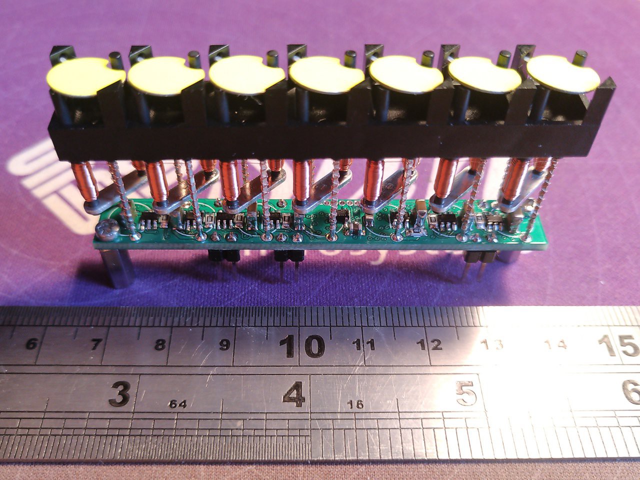
To get a lay of the land, I initially looked into how commercial displays are constructed. They look to be made of an injection molded plastic piece with a flippable dot dangling between two posts at the top. Below there is a U-shaped iron core with tons of copper windings wound around it to create a magnetic field that then interacts with a magnet in the dot to do the actual flipping. I'm really not sure how they make these things in a cost-effective and highly automated fashion. I cannot find any videos online as to how they do it. Here's an image showing the general idea of how they're constructed:
![]()
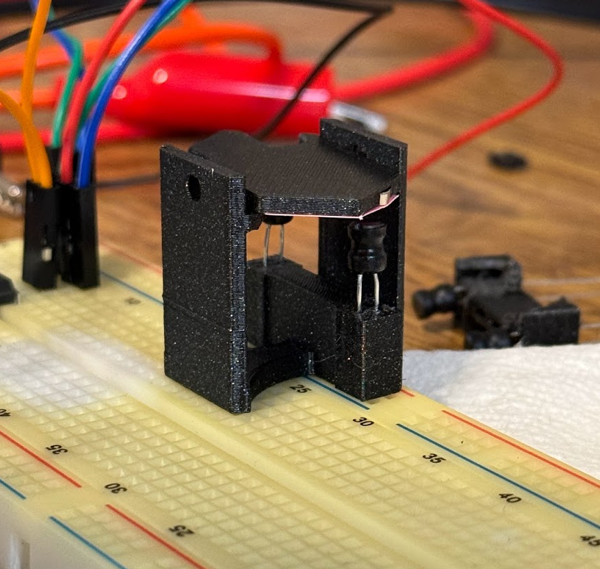
I started mulling about how I would make my own dots. Would I try to build a machine to make them exactly like how existing ones are currently made? That seems challenging to say the least, as they likely have some precision winding and soldering machine to do it for them that took a lot of time and money to build. The real challenge is going to be the copper wire - specifically attaching the copper wire to the drive PCBA. I looked around for surface mount or through-hole electromagnets, but they don't exist (and why would they?), but then I was struck with an idea. What about inductors? They're just big electromagnets. I learned there are actually 2 types of inductors, shielded, where the core material extends all the way around the coils to keep the flux contained, and unshielded, where the flux flows through air for some portion of its trip. This makes unshielded inductors an interesting potential candidate for my use case, so I whipped up a Digikey order to try things out and got to CAD modelling. I came up with this:
The first fliphex. You can see the two through-hole, unshielded inductors acting as electromagnets to push/pull the magnet in the hex. This design actually worked! See video below
But... this prototype has several issues that ended up making this a non-starter for a big array. In no particular order:
- The inductors are too large for the magnetic field they deliver
- The inductors are WAY too expensive to make a big array out of
- The inductors are finicky with their position, and do not have a clear +/- labeling on them, meaning if I wanted to assemble an array and not do tons of software work, I would have to manually test each inductor and mark the current flow direction to get the desired magnetic field.
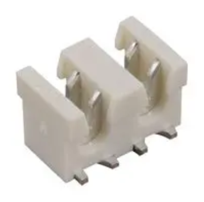
The next approach I thought about taking was one where I did try to make a fliphex winding machine, but do it in a super low cost manner. I thought maybe if I bought a super low cost CNC machine off Amazon, I might be able to 3D print some type of head to go on it that might allow me to wind copper coils. This still does not solve the biggest issue with that though, which is that you need to connect the copper coil flying leads to a PCB in a quick, cheap, and efficient manner. I came across IDC connections as a potential solution to this issue, where would would solder down a surface mount IDC thing, then would come back later and press in your wire connections.
This doesn't sound terrible until you consider that I would have to press in literally thousands of wires by hand, which again made this a non-starter. I also considered having the winding machine wind wires up a pin header pin, then when I soldered in the pin header, it would melt off the enamel insulation on the copper wire. This doesn't sound as terrible, but would then rely a lot on how I managed to get the copper wire to stay in the right spot in the pin header pin. This all also hinges on me being able to mechanically design a head capable of unspooling and cutting copper wire in just the right way such as to wind 32awg wire exactly where I want it, which certainly would be a challenge in its own right.
Truthfully though, I'm an electrical engineer, not a mechanical one, so I'd much rather stick to what I'm comfortable with, and that's in my PCB design suite (KiCAD). I started to put 2 and 2 together. I have already written a program that lets me craft PCB coils in KiCAD, and I know that works based on my last project the OS3M mouse. So that got me thinking... could I use a PCB coil with a center iron core to make an electromagnet? Well, you'll have to wait until the next update to find out. Thanks for reading!
Fliphex - 3D Printed Flip Dots
My quest to mass produce flip dots economically using PCBs and 3D printing
 colton.baldridge


