| State of Buck Converter | State of ST-Link 3.3V pin | Vs | Vo (V) | Io (mA) | State Name |
| 9V plugged in, output 3.3V | Plugged in, Output 3.3V | Buck | 3.3 | 10 | A1 |
| 9V plugged in, output 3.3V | Unplugged, Open Circuit | Buck | 3.3 | 10 | A2 |
| 9V Unplugged, High Output Impedance Buck | Plugged in, Output 3.3V | ST-Link | 3.3 | 10 | A3 |
| 9V Unplugged, High Output Impedance Buck | Unplugged, Open Circuit | None | GND | 0 | A4 |
| 9V Unplugged, Low Output Impedance Buck | Plugged in, Output 3.3V | ST-Link | 3.3 | 10 | A5 |
| 9V Unplugged, Low Output Impedance Buck | Unplugged, Open Circuit | None | GND | 0 | A6 |

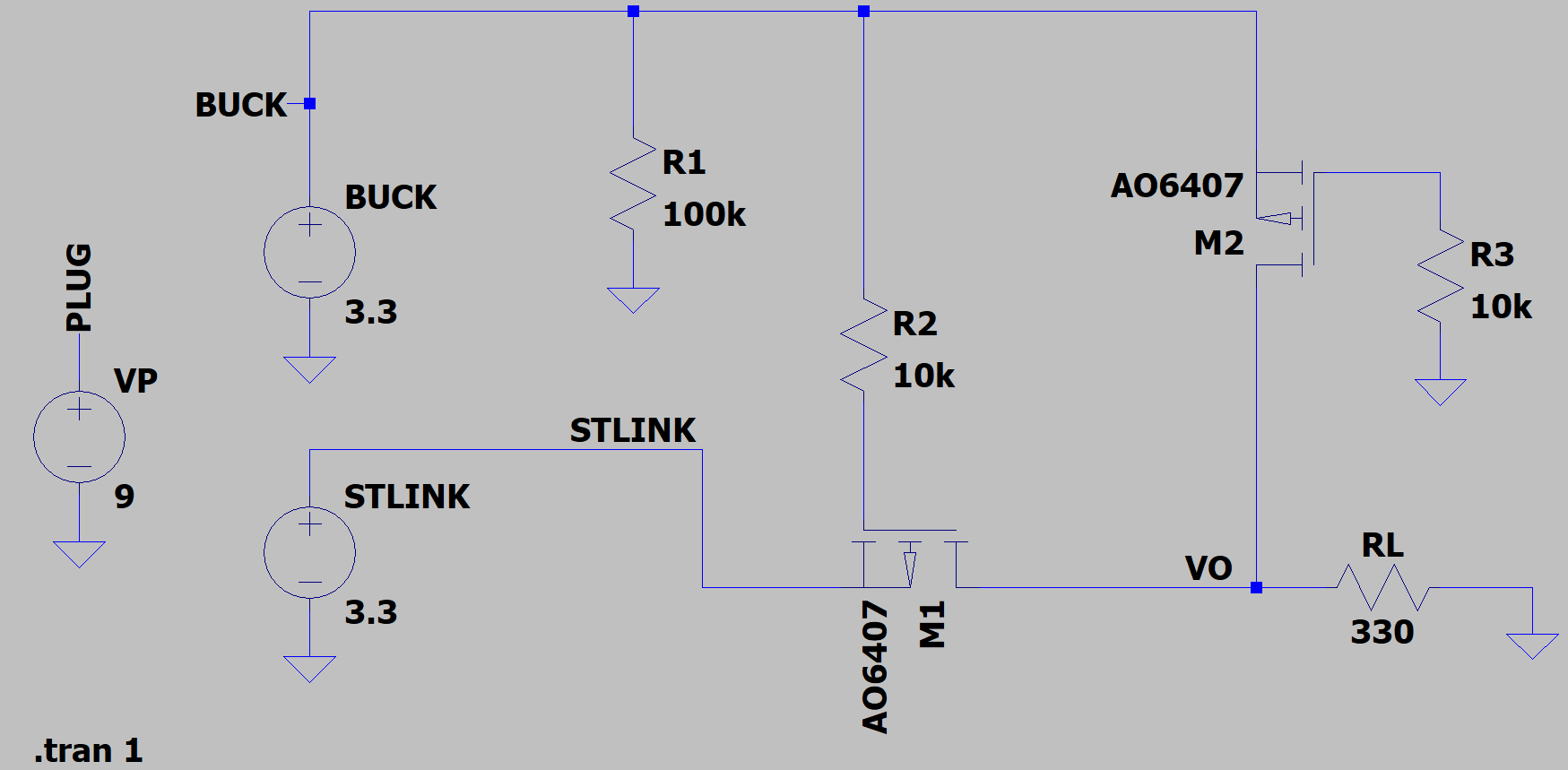
- Updated simulation schematic to better reflect the hardware implementation
- Made a table of the different states the power selector can take, along with the expected output
- ***Depending on the design of the buck converter, the output impedance when it is not receiving power can be so high it is basically an open circuit or "low"
- Either way, you don't want to develop a potential at the output terminal if it is disconnected from it's own power source
- Will make a separate file for each state instead of trying to simulate them in the same transient simulation
 Ghani Lawal
Discussions
Become a Hackaday.io Member
Create an account to leave a comment. Already have an account? Log In.