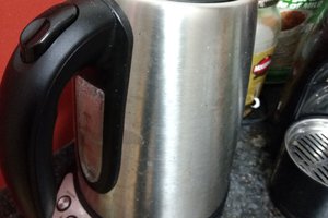
I've been using the Bonavita 1-Liter Variable Temperature Digital Electric Gooseneck Kettle for my pour-overs for a couple of years now. The device is a well-designed product that has been time-tested in cafes around the world.
What nobody asked for was WiFi and smart home support, so I've set about doing just that.
Let me start at the end:
The default behavior when powering on the kettle is to display the set temperature, bring the water up to that temperature, and then turn off the heat once the set temp has been reached. The kettle also offers a "hold" button which, when pressed, will instruct the kettle to bring the water up to the set temperature and keep it there for 60 minutes at which point it'll shut down. The "hold" function is all I ever use, so every time I turn the kettle on I then press "hold" immediately thereafter.
Ain't nobody got time for that!
The first order of business was detecting when the kettle has been turned on and then moments later pressing the "hold" button. You see this behavior in the beginning of the video, where the device detects the kettle powering on by monitoring the red power LED to the left. A couple hundred milliseconds after that LED comes on, the "hold" button is pressed to automatically place the kettle in "hold" mode (green LED) after every power on.
Next, the device publishes its state (on or off) to MQTT which sends messages to and from my SmartThings home automation platform. The app you see on the tablet is the standard SmartThings mobile app showing the kettle's current power state and then toggling the device on and off. Once the device is accessible in SmartThings I can trigger the devices in a zillion different ways. For example, SmartThings offers integration with the Amazon Echo so I can also control the kettle via voice commands.
I first knocked together a simple solution to trigger the "power" switch via a relay:

That gave way to a SmartThings Zigbee shield, an Arduino, some optoisolators, and a few clicky relays:

The trouble was that this arrangement was large and would require a separate box sitting on the counter next to the kettle along with a separate wall wart to power it which didn't seem ideal. Then I discovered the ESP8266 family of microcontrollers which allowed me to use a much smaller WiFi-enabled device which could conceivably be shoehorned into the kettle.
To get it wired in I needed to figure out where I could access a couple four things: I needed a source of DC power, I needed to be able to monitor the power LED, and I needed a way to press the "power" and "hold" buttons. Here is what I came up with:

- VCC +5V DC (kinda, more on that below)
- Ground
- Button common
- Power button
- Hold button
- Power LED (negative logic, so +5V == off)
Using this map I soldered in a ribbon cable and put a dupont connector on the end for easy connections:

The microcontroller I'm using has an onboard power supply to convert 5VDC into the 3.3VDC it's expecting, but every time I'd power it up something went wrong. I spent quite a while tracking that down using external regulation and filter caps but couldn't get the microcontroller to power up. Eventually I looked at it with my oscilloscope which allowed me to see the +/-1V 60Hz swings in voltage coming from the kettle's built-in PSU. In response I tore open a wall-wart USB charger, stole the guts, then wrapped it in heat shrink and stuck it inside the kettle. With a stable power supply I was able to reliably control the kettle via 3 optoisolators to fully isolate the microcontroller from the kettle's own dodgy power.

The next step was to condense this down into a package that could fit inside the base so I got some perfboard and set myself to hacking together this mess of tiny wires (that's 30awg kynar).


The resulting combination of microcontroller and isolator interface board turned out to be small enough for my purposes. A 5mm LED is placed next to this for scale:

I positioned the power supply and microcontroller board...
Read more » luma
luma


 Saabman
 mircemk
 scott.mcgimpsey
what are the mystery optoisolators used here?