Close
0%
0%

Custom 5x5 Keypad

Made a 5x5 keypad matrix from scratch.

Similar projects worth following
0 followers
Hello everyone, and welcome back. Here's something fun and useful. The customized 5x5 button matrix board built from scratch.
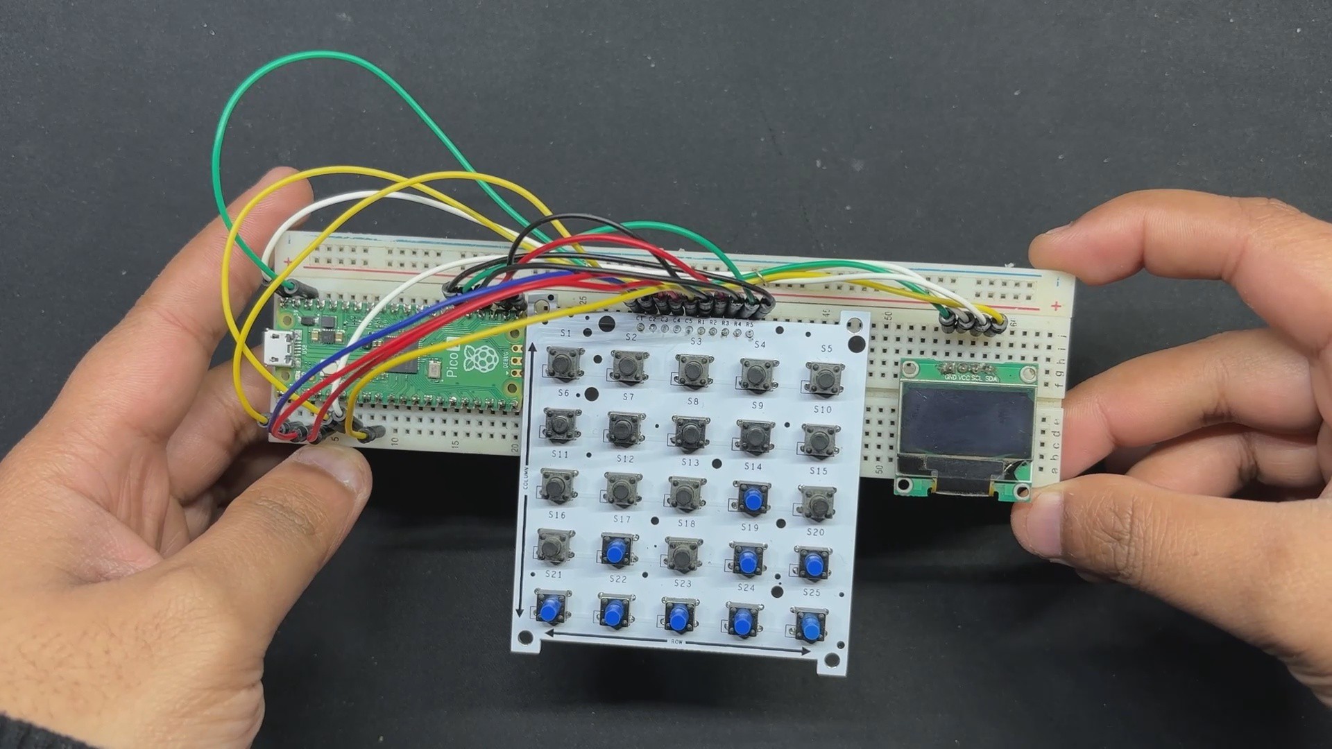
Here, we create a simple 25-button matrix board using a simple row-and-column framework, with buttons arranged in five rows and five columns to form a button grid. When you press the button, it completes the circuit between a row and a column, which is detected by the microcontroller and shown on the OLED screen.

The purpose of developing this project was to work on a calculator project that required as many buttons as possible; thus, we created this matrix board to aid us in the tinkering phase of the calculator project.

Keypad Design Process
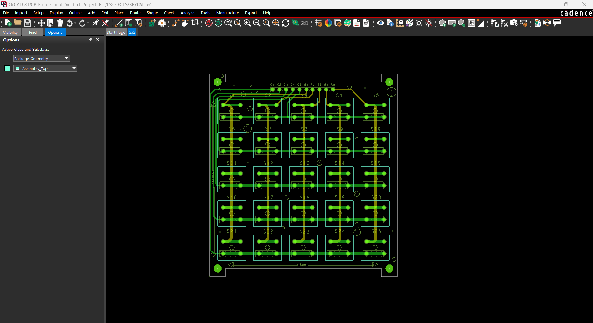
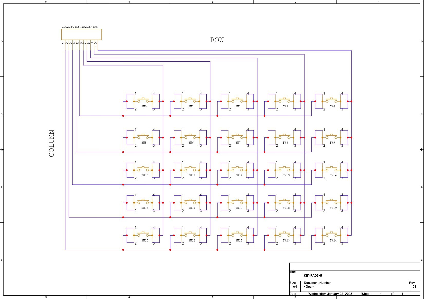
We started with our project by arranging all of the buttons in five rows and five columns.

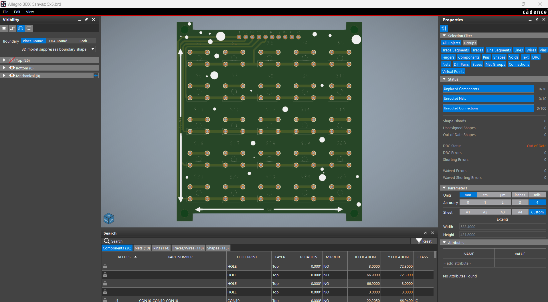
We created a button matrix (inspired by a key matrix board) in which all buttons are placed in a grid of rows and columns, with each row and column connected to a CON10 header pin connector.

The microcontroller scans the matrix by setting each row high and then checking each column. Pressing the button completes the circuit between a row and a column. Knowing which row is high and which column reads the signal allows the microcontroller to determine which button is pressed.

This method decreases the amount of I/O pins required, as we are using 25 buttons, and a standard method would require 25 I/O pins for all buttons; however, this method allows us to utilize only 10 I/O pins overall.

By creating the schematic, we were able to export the netlist and develop the board design for this project, which included placing the buttons in the GRID configuration and linking the traces according to the schematic. We completed the board and then exported the gerber data, which will be shared with a PCB manufacturer to create samples.

Seeed Studio Fusion
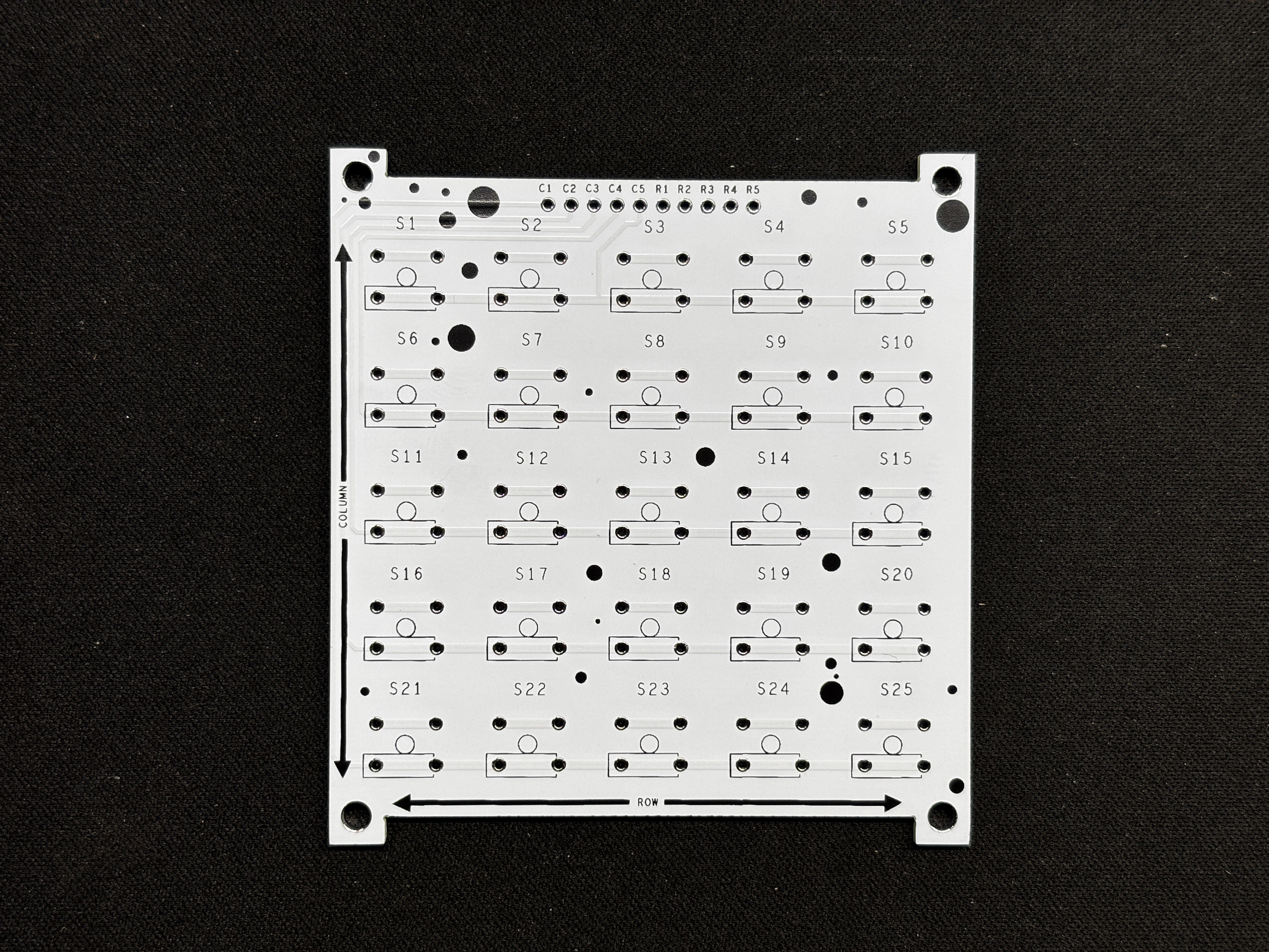
Following the completion of the Gerber data, we uploaded the file to Seeed Fusion's website and placed an order for a white Solder mask with black silkscreen.

PCBs were received in a week, and their quality was super good considering the rate, which was also pretty low.

Seeed Fusion PCB Service offers one-stop prototyping for PCB manufacture and PCB assembly, and as a result, they produce superior-quality PCBs and fast turnkey PCBAs within 7 working days.

Seeed Studio Fusion PCB Assembly Service takes care of the entire fabrication process, from Seeed Studio Fusion Agile manufacturing and hardware customization to parts sourcing, assembly, and testing services, so you can be sure that they are getting a quality product.

After gauging market interest and verifying a working prototype, Seeed Propagate Service can help you bring the product to market with professional guidance and a strong network of connections.

5X5.rar

x-compressed - 13.50 kB - 01/11/2025 at 05:09

Download

SCH.pdf

Adobe Portable Document Format - 160.84 kB - 01/11/2025 at 05:09

Preview

  • 1
    PCB Assembly process
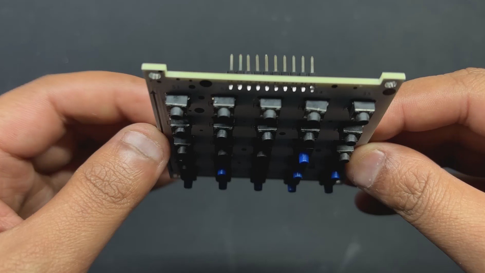
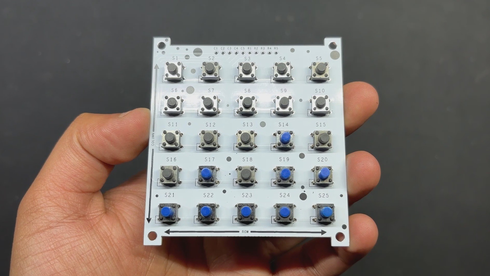
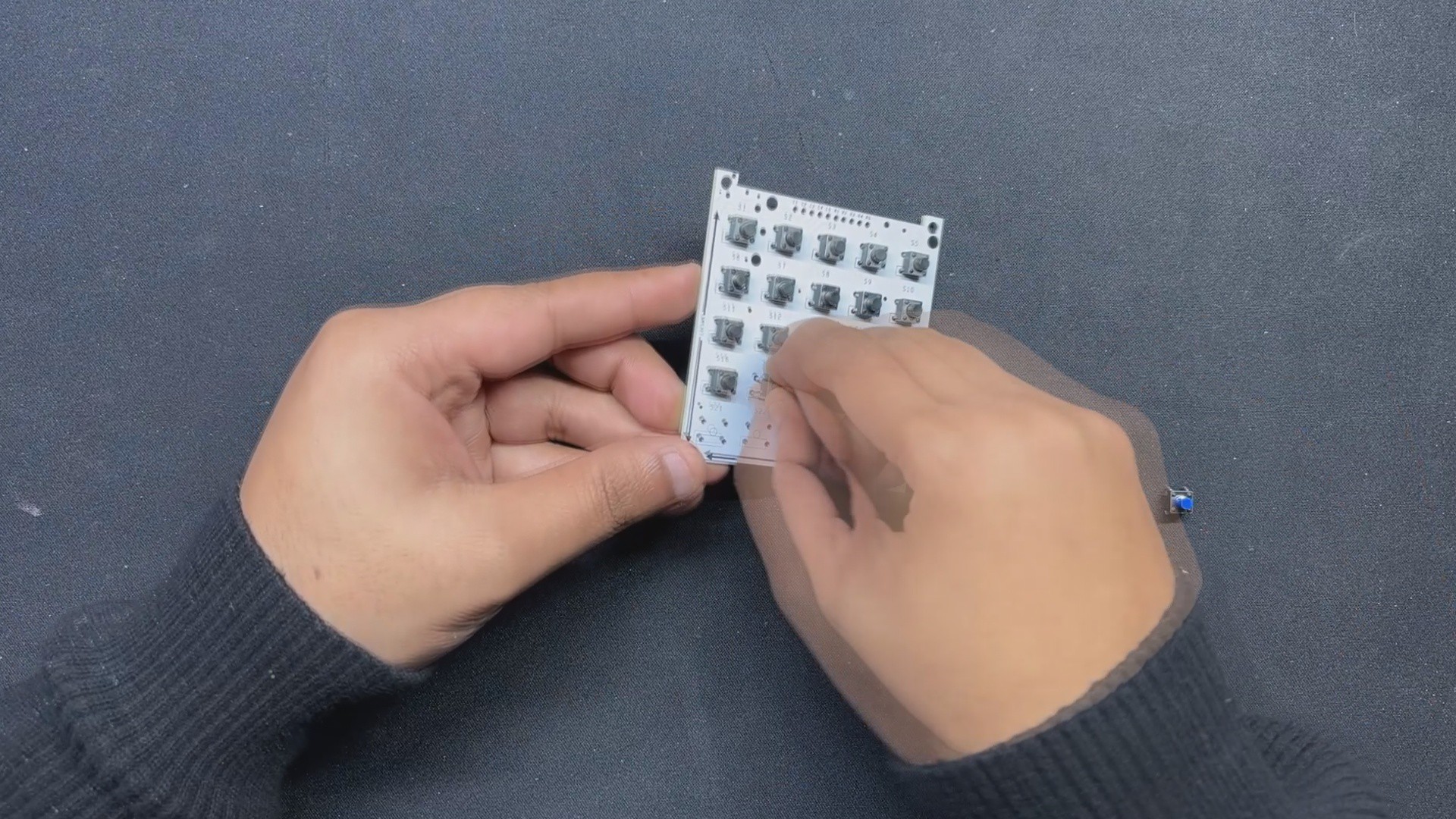
    • The assembly process begins with placing all 25 switches in their respective pads on the Matrix PCB; we are utilizing 6x6 Tacktile buttons here, and we must ensure that all buttons are correctly added to their pads, as some of the buttons' pins bend when placed in the footprint.
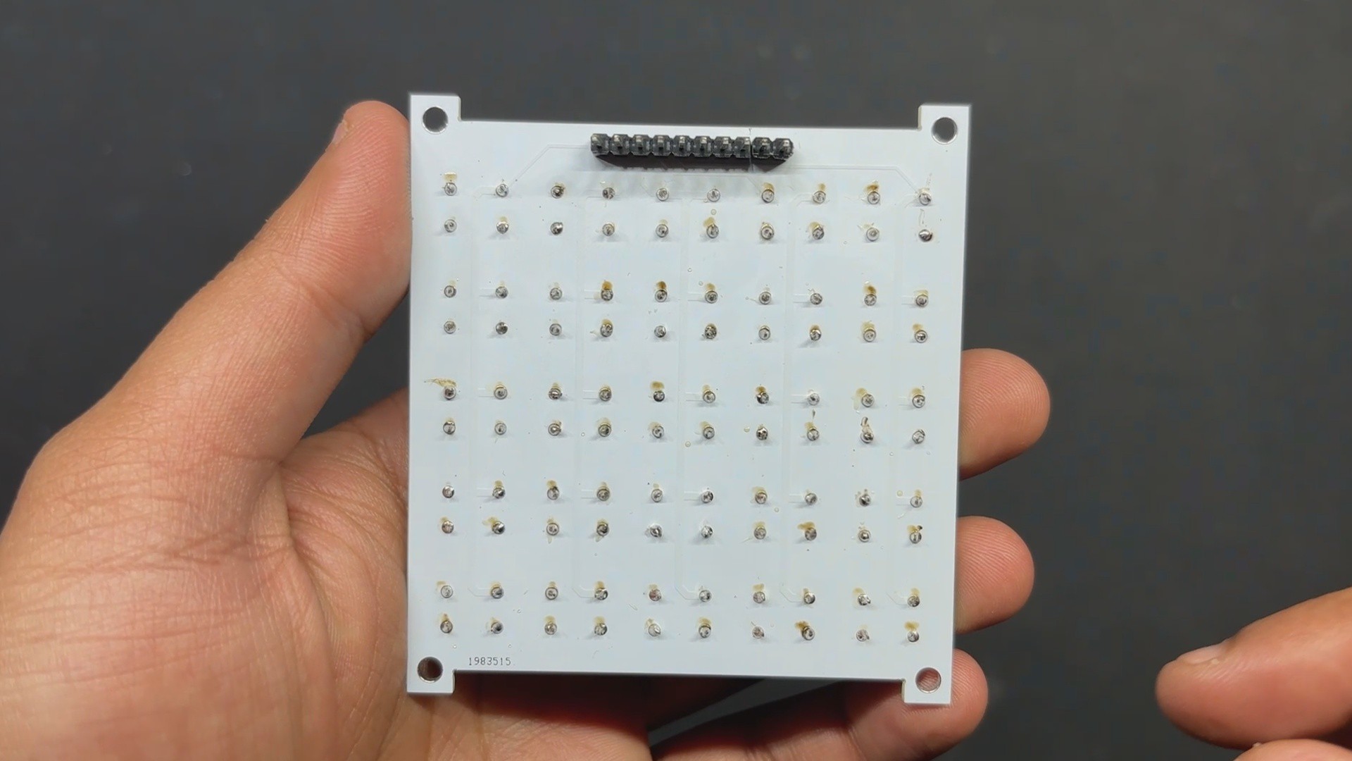
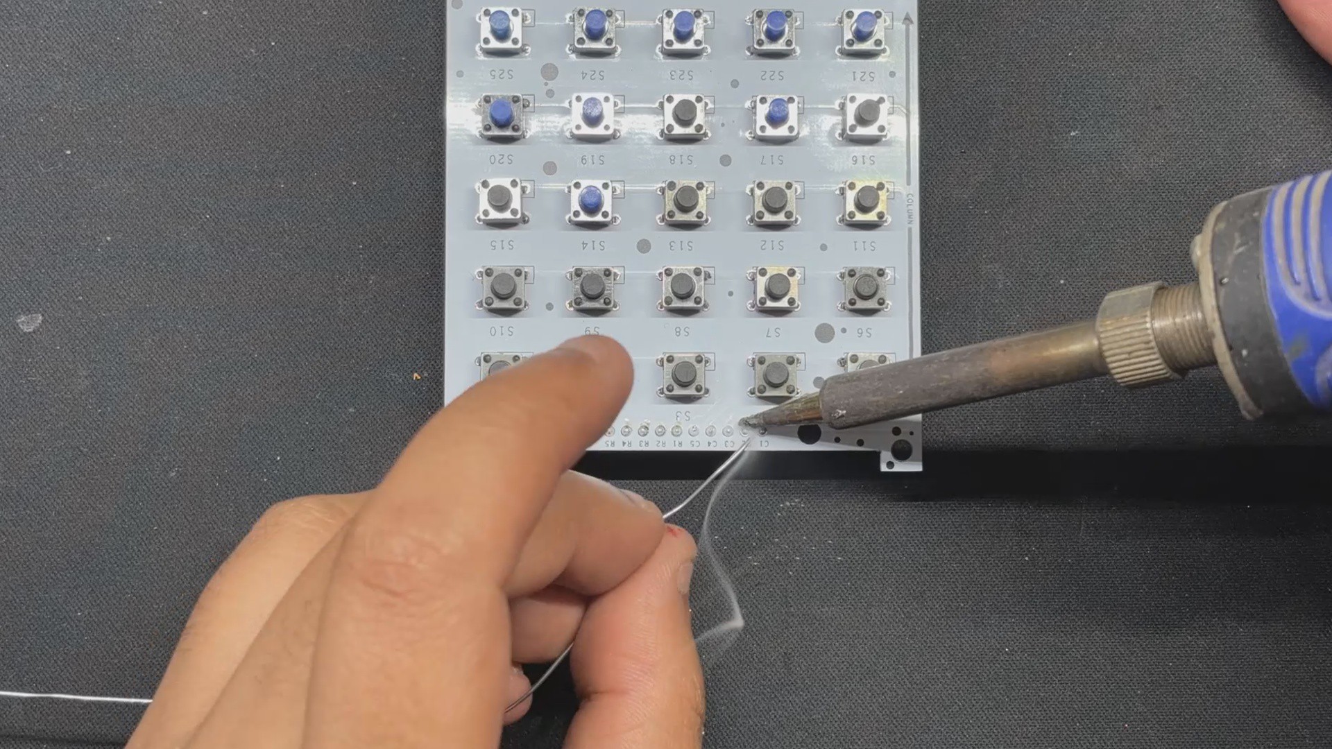
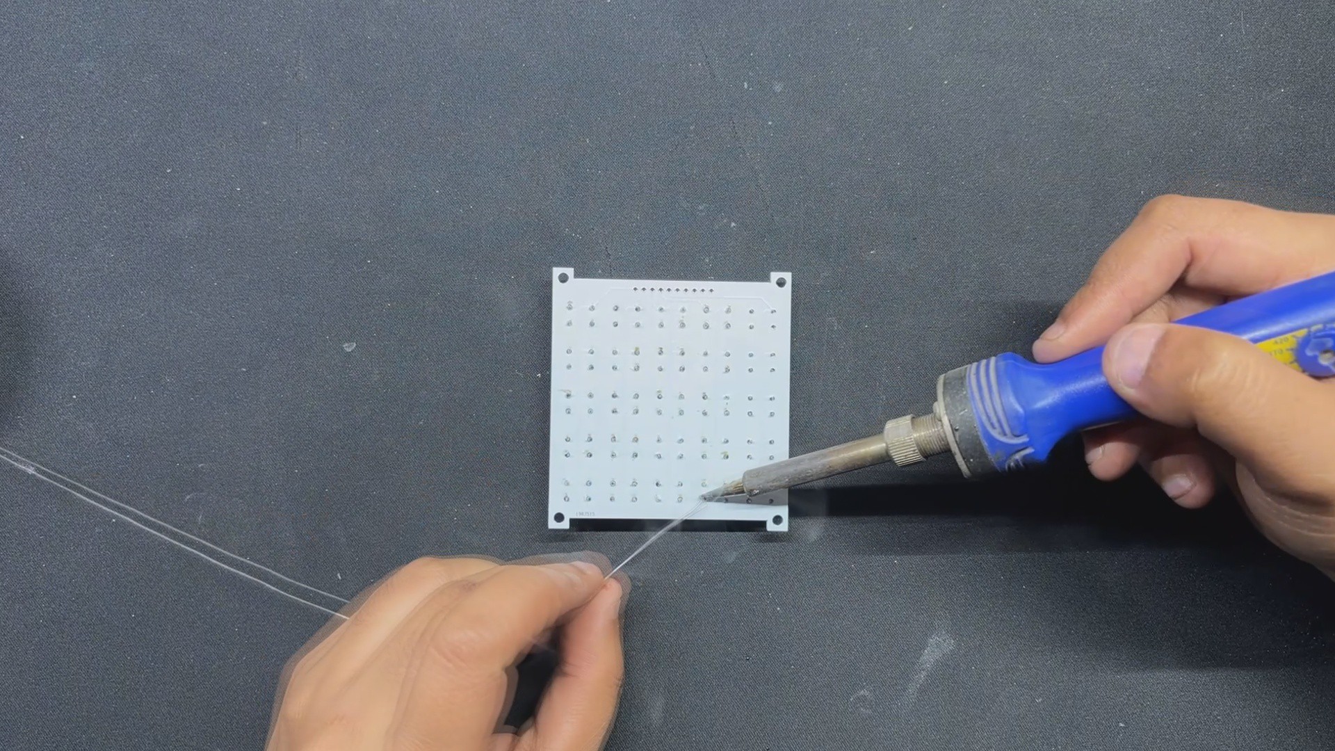
    • Next, we solder all of the switch pads on the bottom side of the board with a soldering iron.
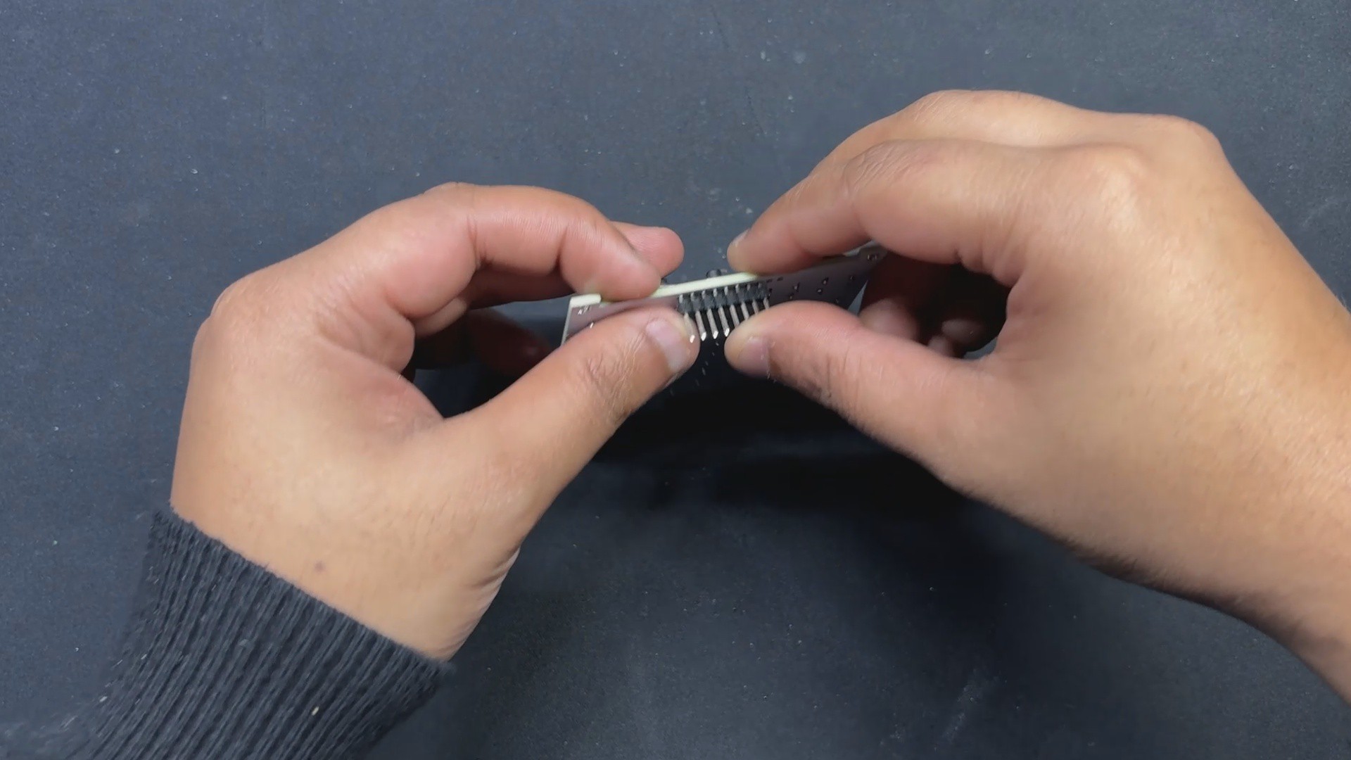
    • Following that, we place a CON10 male header pin in its place and solder its pads from the top side of the board.

    Matrix Board is now assembled.

  • 2
    Raspberry Pi Pico Setup
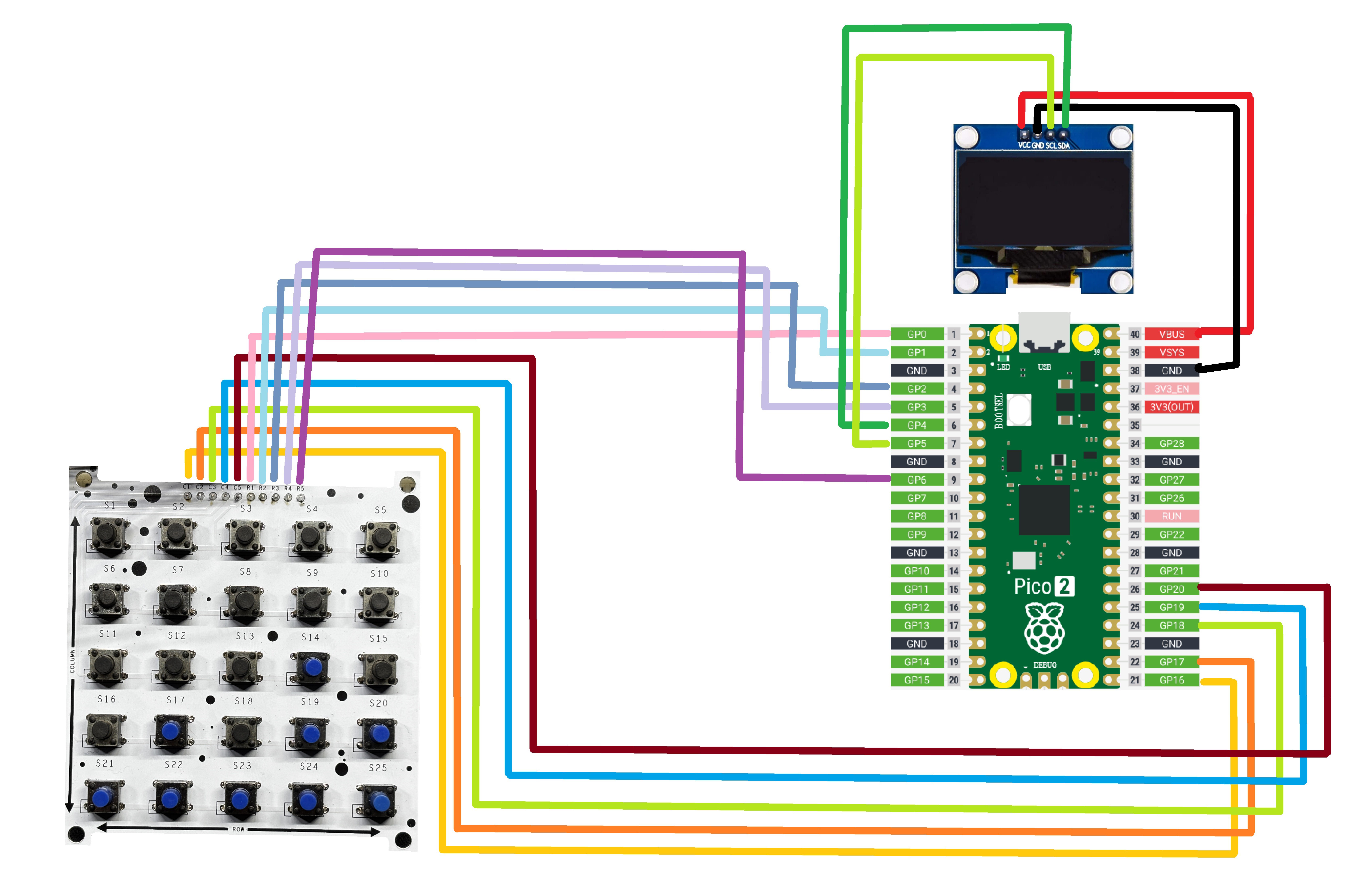
    • Using a PICO 2, an OLED display, a breadboard, a button matrix, and a few jumper wires, we create a basic setup by connecting all of the column pins from C1 to C5 with GPIO16, GPIO17, GPIO18, GPIO19, and GPIO20.
    • GPIO0, GPIO1, GPIO2, GPIO3, and GPIO6 connect rows 1 through 5.
    • The OLED screen's VCC is connected to PICO's VBUS, while the GND is connected to GND.
    • The SDA of the OLED is linked to PICO's SDA Pin (GPIO4), and the SCL is attached to GPIO5, which is PICO's SCL Pin.
  • 3
    CODE

    Here's a quick test drawing we created to see if all of the button mapping is right.

    #include <Wire.h>
    #include <Adafruit_GFX.h>
    #include <Adafruit_SSD1306.h>
    // Define OLED display dimensions
    #define SCREEN_WIDTH 128
    #define SCREEN_HEIGHT 64
    // Initialize the OLED display with I2C address 0x3C
    Adafruit_SSD1306 display(SCREEN_WIDTH, SCREEN_HEIGHT, &Wire, -1);
    // Swap rows and columns
    const int rows = 5;
    const int cols = 5;
    const int colPins[cols] = {16, 17, 18, 19, 20}; // Now column pins
    const int rowPins[rows] = {0, 1, 2, 3, 6}; // Now row pins
    int lastButtonPressed = -1;
    void setup() {
    Serial.begin(115200);
    // Initialize the OLED display
    if (!display.begin(SSD1306_SWITCHCAPVCC, 0x3C)) {
    Serial.println(F("SSD1306 allocation failed"));
    for (;;);
    }
    display.clearDisplay();
    // Initialize row pins as inputs
    for (int i = 0; i < rows; i++) {
    pinMode(rowPins[i], INPUT_PULLUP);
    }
    // Initialize column pins as outputs
    for (int i = 0; i < cols; i++) {
    pinMode(colPins[i], OUTPUT);
    digitalWrite(colPins[i], HIGH);
    }
    }
    void loop() {
    bool buttonPressed = false;
    for (int row = 0; row < rows; row++) {
    digitalWrite(rowPins[row], LOW); // Activate row
    for (int col = 0; col < cols; col++) {
    if (digitalRead(colPins[col]) == LOW) { // Button press detected
    lastButtonPressed = (rows - row - 1) * cols + col + 1; // Reverse button order calculation
    buttonPressed = true;
    delay(50); // Further reduced debounce delay
    }
    }
    digitalWrite(rowPins[row], HIGH); // Deactivate row
    if (buttonPressed) {
    break; // Exit the loop once a button press is detected
    }
    }
    // Display the last button pressed only if there's an update
    if (buttonPressed) {
    display.clearDisplay();
    display.setTextSize(2); // Set text size larger
    display.setTextColor(WHITE);
    display.setCursor(0, 10); // Center text vertically
    display.print("Btn: ");
    display.print(lastButtonPressed);
    display.display(); // Update the display
    }
    }

    This code initializes an OLED display and sets up a button matrix with swapped rows and columns to detect button presses. When a button is pressed, it identifies which button was pressed, displays the button number on the OLED screen, and updates the display accordingly.

    We are using the Adafruit_SSD1306 Library in this sketch, which you need to download and install first before using this code.

View all 4 instructions

Enjoy this project?

Share

Discussions

Similar Projects

Does this project spark your interest?

Become a member to follow this project and never miss any updates