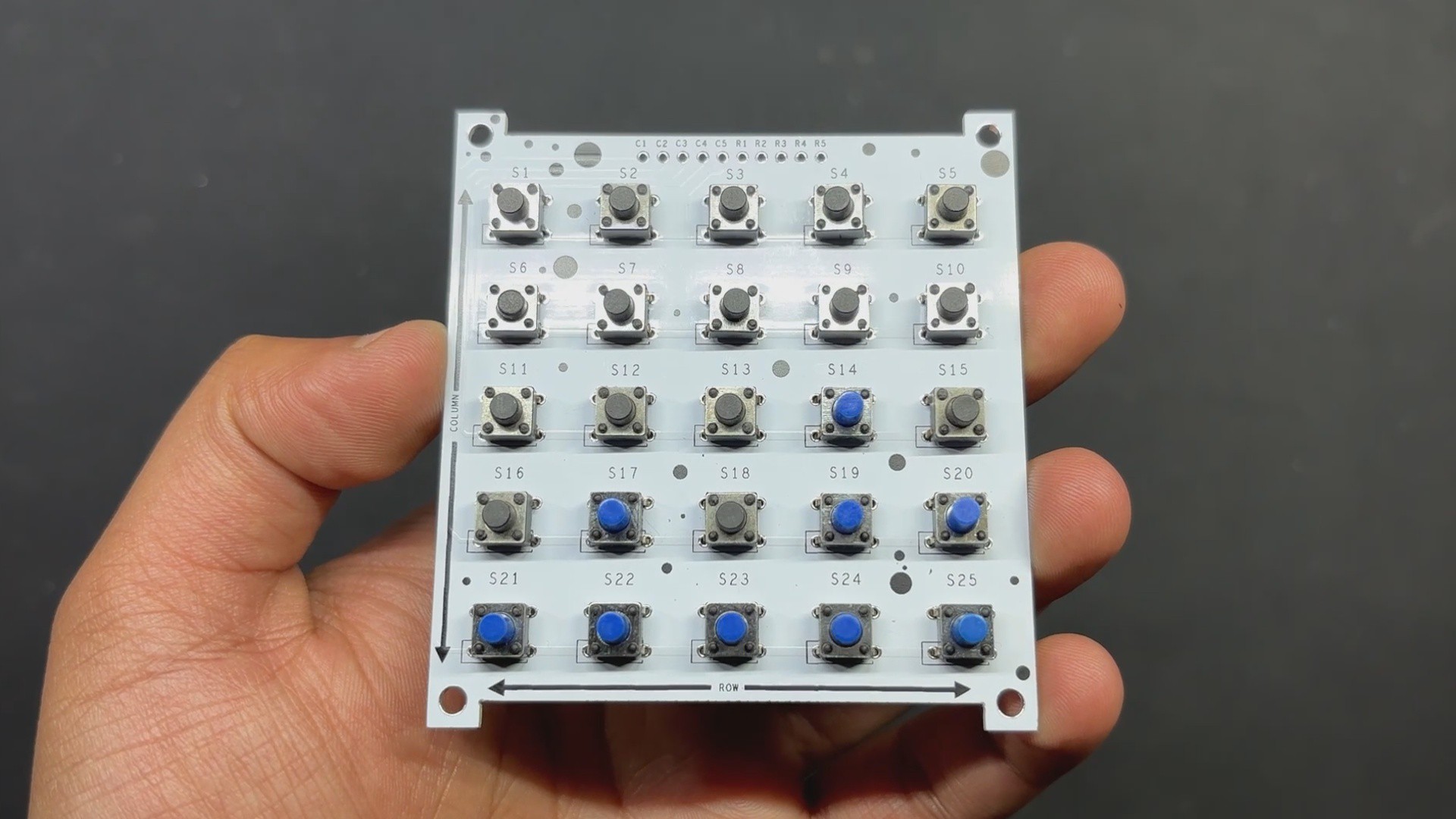
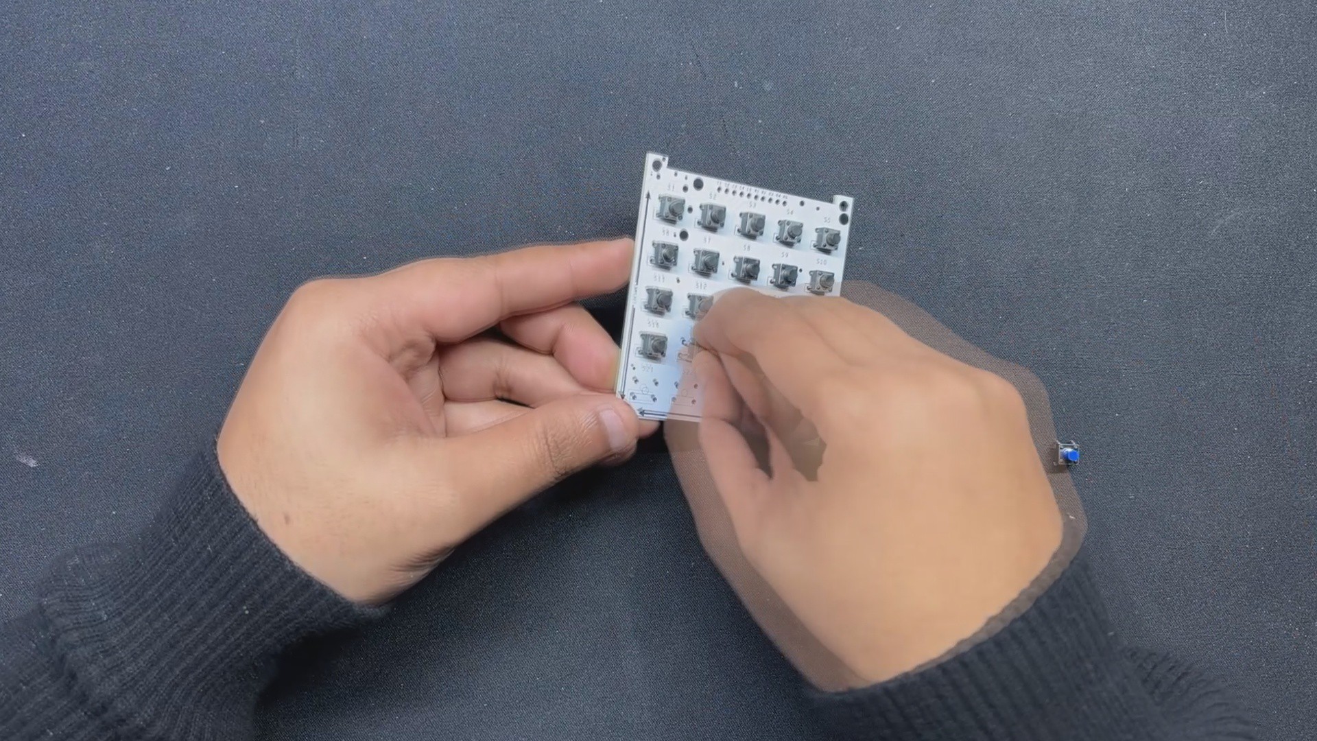
The assembly process begins with placing all 25 switches in their respective pads on the Matrix PCB; we are utilizing 6x6 Tacktile buttons here, and we must ensure that all buttons are correctly added to their pads, as some of the buttons' pins bend when placed in the footprint.
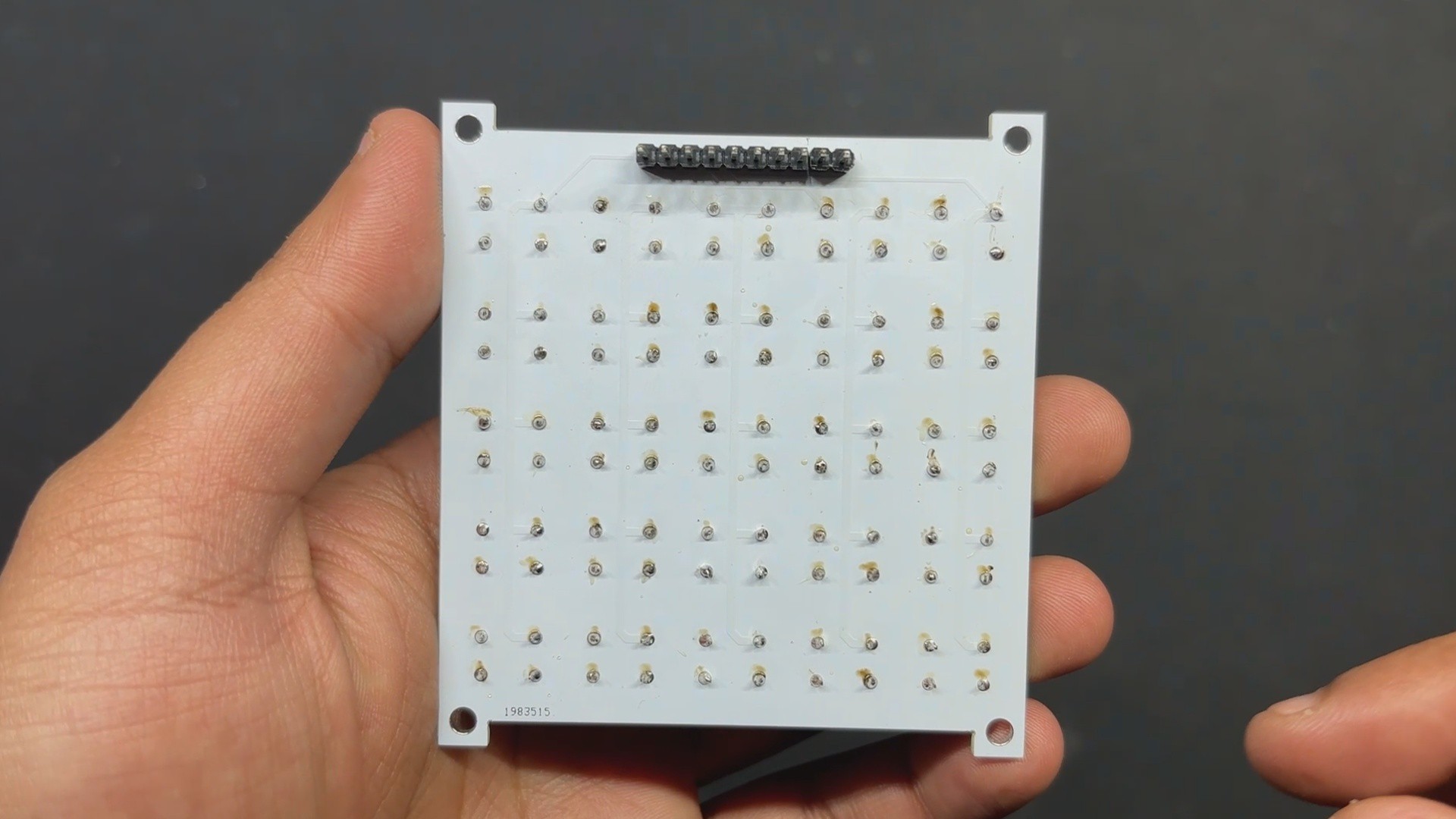
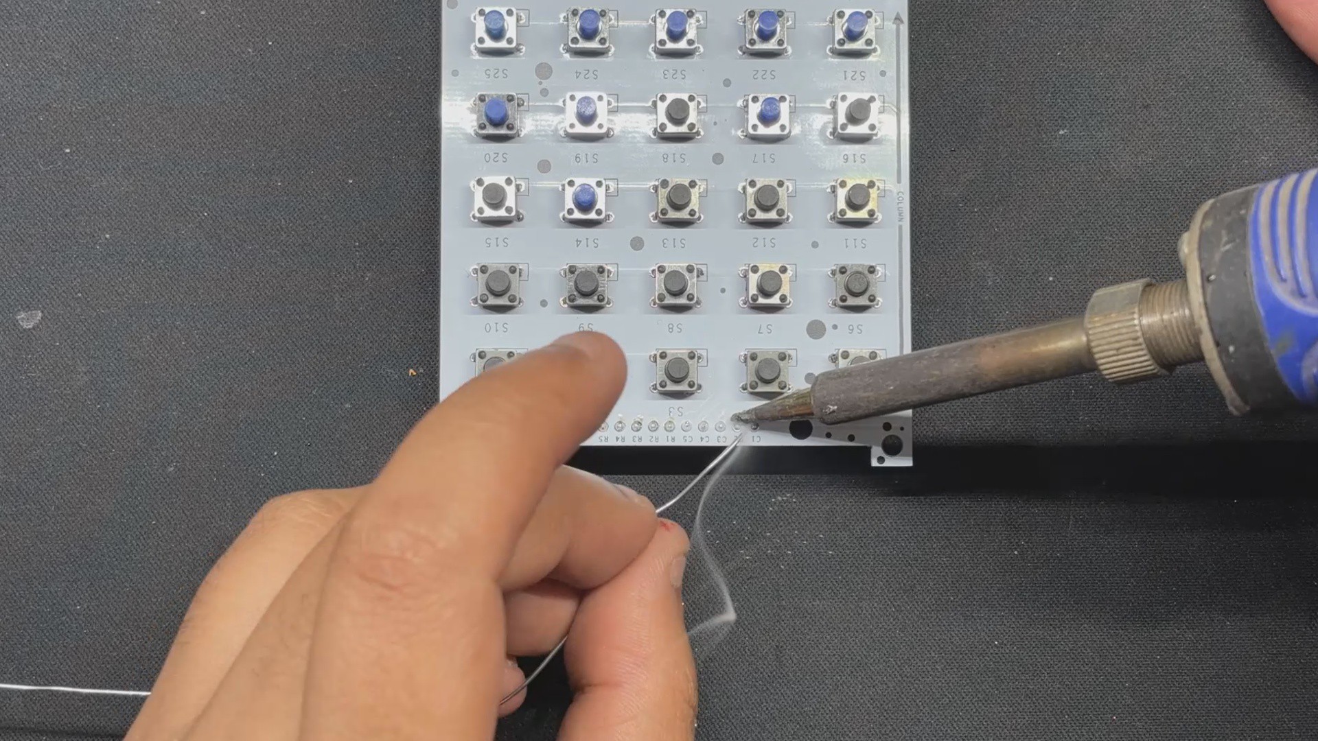
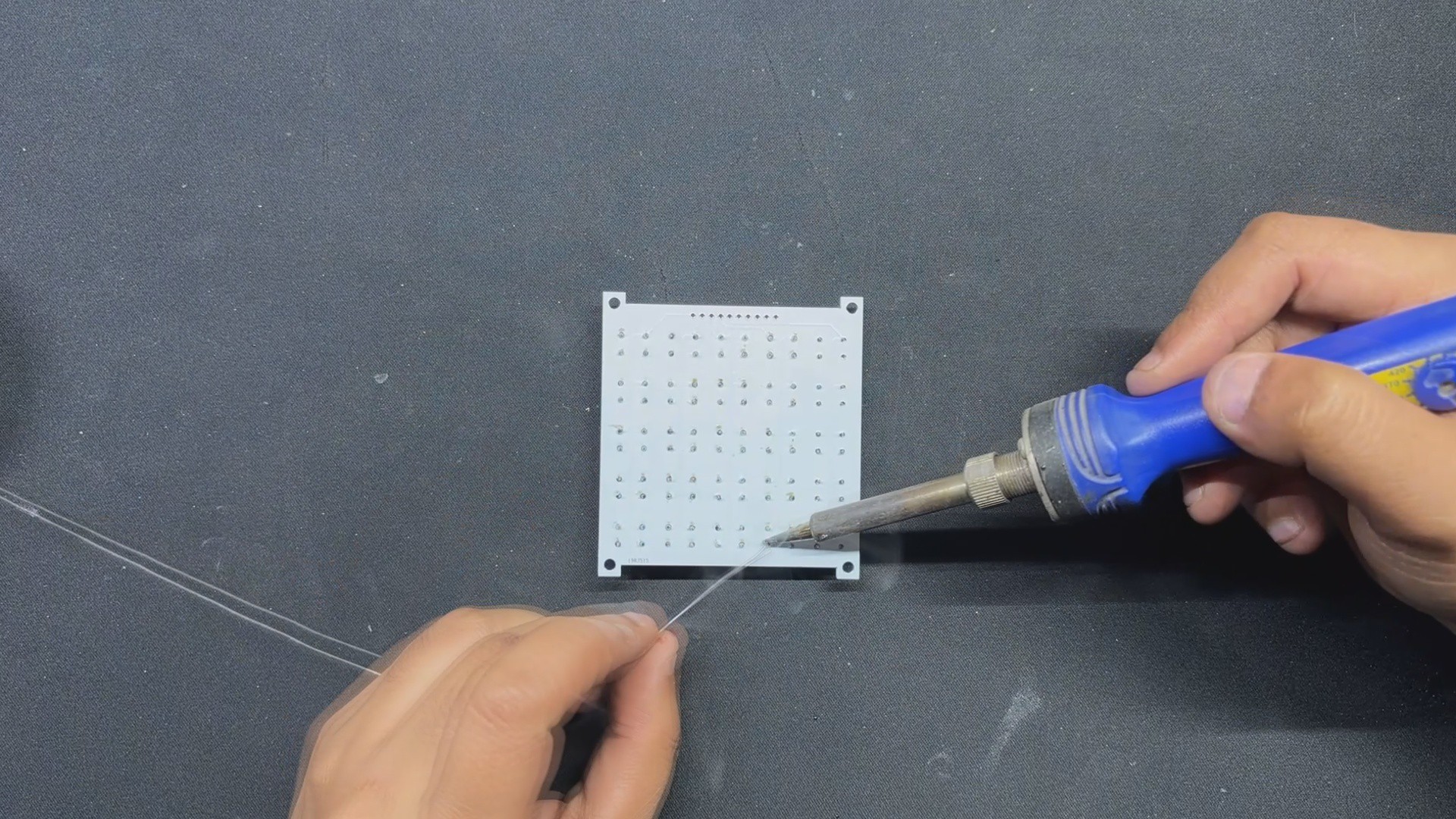
Next, we solder all of the switch pads on the bottom side of the board with a soldering iron.
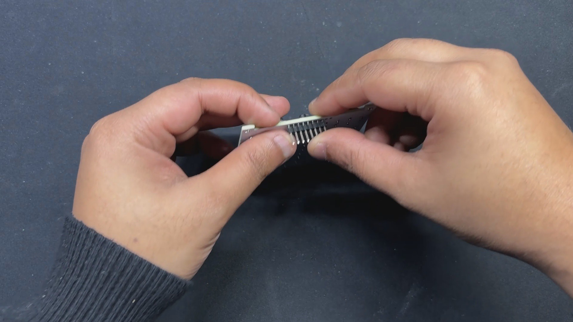
Following that, we place a CON10 male header pin in its place and solder its pads from the top side of the board.
Matrix Board is now assembled.
2
Raspberry Pi Pico Setup
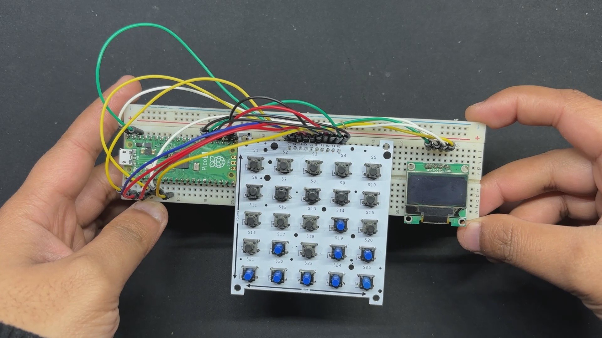
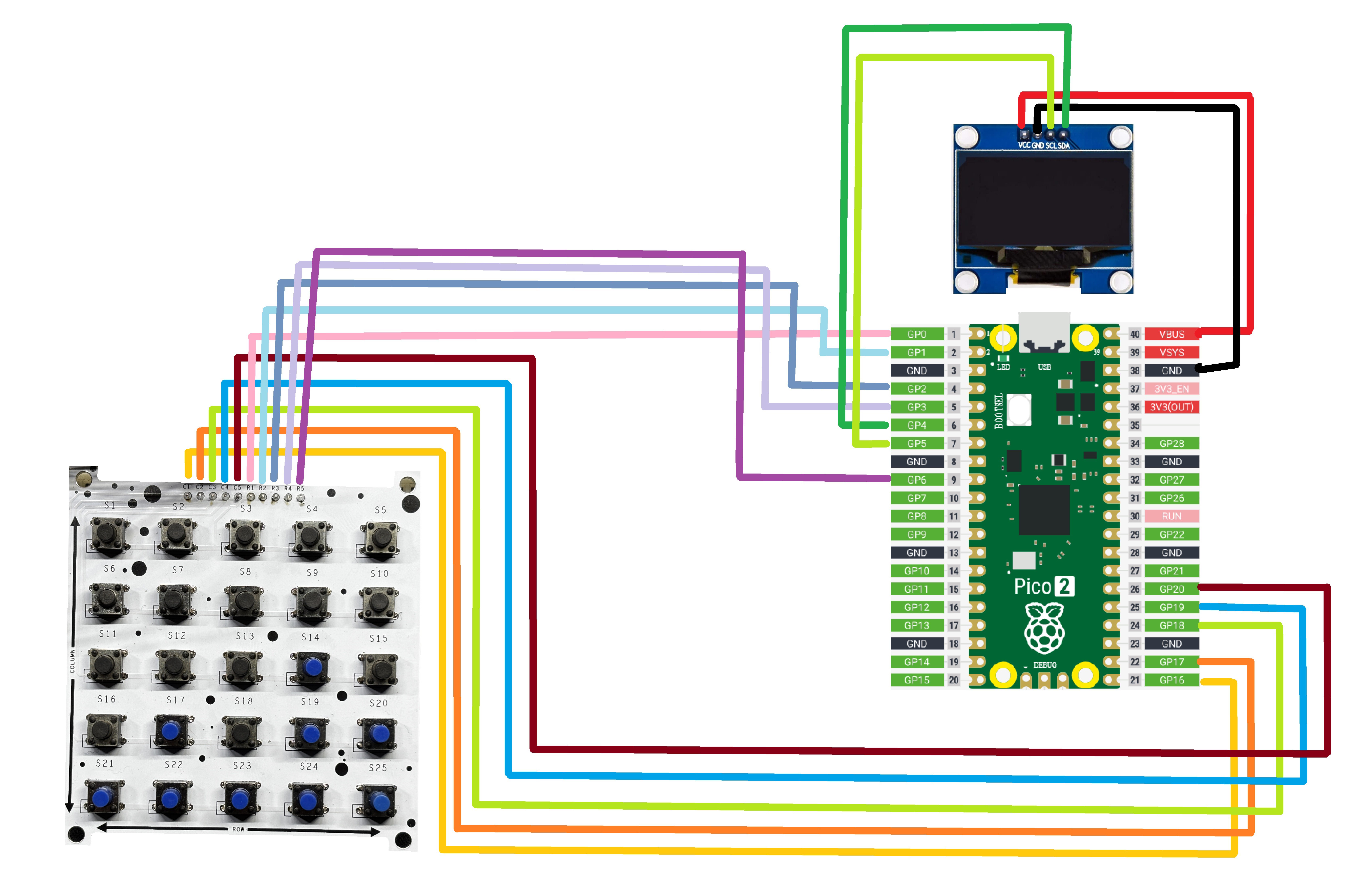
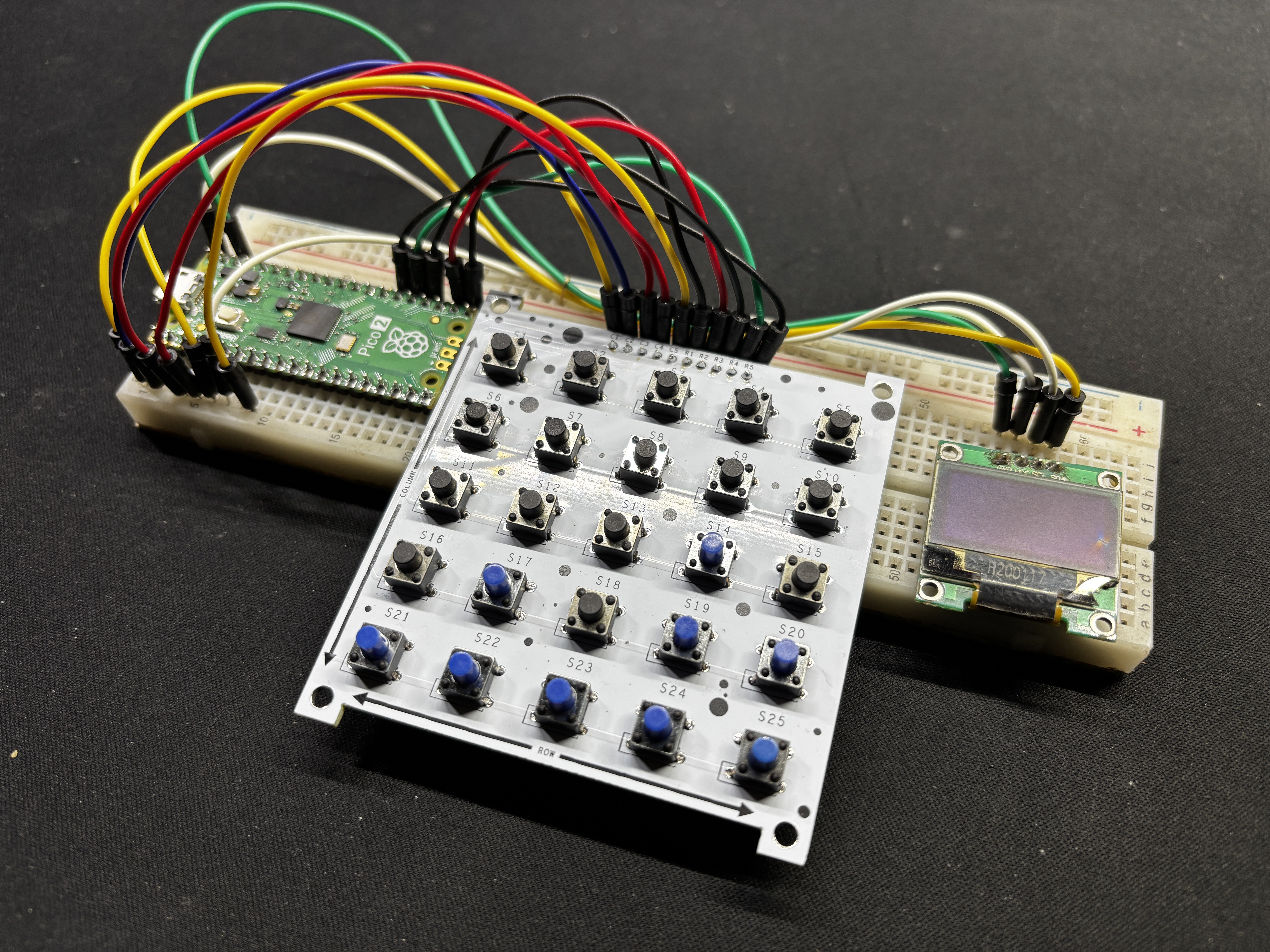
Using a PICO 2, an OLED display, a breadboard, a button matrix, and a few jumper wires, we create a basic setup by connecting all of the column pins from C1 to C5 with GPIO16, GPIO17, GPIO18, GPIO19, and GPIO20.
GPIO0, GPIO1, GPIO2, GPIO3, and GPIO6 connect rows 1 through 5.
The OLED screen's VCC is connected to PICO's VBUS, while the GND is connected to GND.
The SDA of the OLED is linked to PICO's SDA Pin (GPIO4), and the SCL is attached to GPIO5, which is PICO's SCL Pin.
3
CODE
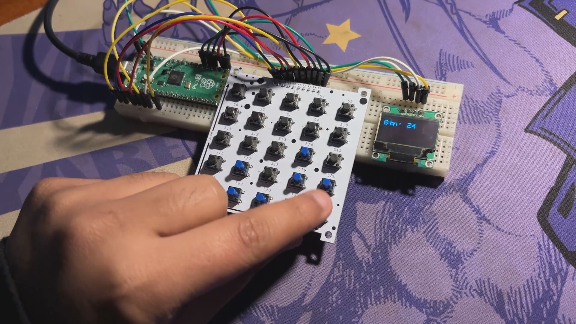
Here's a quick test drawing we created to see if all of the button mapping is right.
#include<Wire.h>#include<Adafruit_GFX.h>#include<Adafruit_SSD1306.h>// Define OLED display dimensions#define SCREEN_WIDTH 128#define SCREEN_HEIGHT 64// Initialize the OLED display with I2C address 0x3CAdafruit_SSD1306 display(SCREEN_WIDTH, SCREEN_HEIGHT, &Wire, -1);
// Swap rows and columnsconstint rows = 5;
constint cols = 5;
constint colPins[cols] = {16, 17, 18, 19, 20}; // Now column pinsconstint rowPins[rows] = {0, 1, 2, 3, 6}; // Now row pinsint lastButtonPressed = -1;
voidsetup(){
Serial.begin(115200);
// Initialize the OLED displayif (!display.begin(SSD1306_SWITCHCAPVCC, 0x3C)) {
Serial.println(F("SSD1306 allocation failed"));
for (;;);
}
display.clearDisplay();
// Initialize row pins as inputsfor (int i = 0; i < rows; i++) {
pinMode(rowPins[i], INPUT_PULLUP);
}
// Initialize column pins as outputsfor (int i = 0; i < cols; i++) {
pinMode(colPins[i], OUTPUT);
digitalWrite(colPins[i], HIGH);
}
}
voidloop(){
bool buttonPressed = false;
for (int row = 0; row < rows; row++) {
digitalWrite(rowPins[row], LOW); // Activate rowfor (int col = 0; col < cols; col++) {
if (digitalRead(colPins[col]) == LOW) { // Button press detected
lastButtonPressed = (rows - row - 1) * cols + col + 1; // Reverse button order calculation
buttonPressed = true;
delay(50); // Further reduced debounce delay
}
}
digitalWrite(rowPins[row], HIGH); // Deactivate rowif (buttonPressed) {
break; // Exit the loop once a button press is detected
}
}
// Display the last button pressed only if there's an updateif (buttonPressed) {
display.clearDisplay();
display.setTextSize(2); // Set text size larger
display.setTextColor(WHITE);
display.setCursor(0, 10); // Center text vertically
display.print("Btn: ");
display.print(lastButtonPressed);
display.display(); // Update the display
}
}
This code initializes an OLED display and sets up a button matrix with swapped rows and columns to detect button presses. When a button is pressed, it identifies which button was pressed, displays the button number on the OLED screen, and updates the display accordingly.
We are using the Adafruit_SSD1306 Library in this sketch, which you need to download and install first before using this code.
4
Conclusion
Here's the end result of this small butlt, a DIY Keypad matrix that can be used to add multiple buttons to any project by using only a few I/O pins. In this case, we have a total of 25 buttons that would require 25 I/O pins if connected regularly, but this matrix allows the user to only use 10 I/O pins to control 25 buttons, which is ideal if the microcontroller being used has limited I/O pins.
The purpose of developing this matrix was to create a compact calculator with an OLED screen combined to a Raspberry Pi Pico and a button matrix.
Leave a comment if you need any help regarding this project. This is it for today, folks, and stay tuned for the calculator project update.
Special thanks to Seeed Studio Fusion Service for supporting this project. You guys can check them out if you need great PCB and stencil service for less cost and great quality.
And I'll be back with a new project pretty soon, peace.
 Arnov Sharma
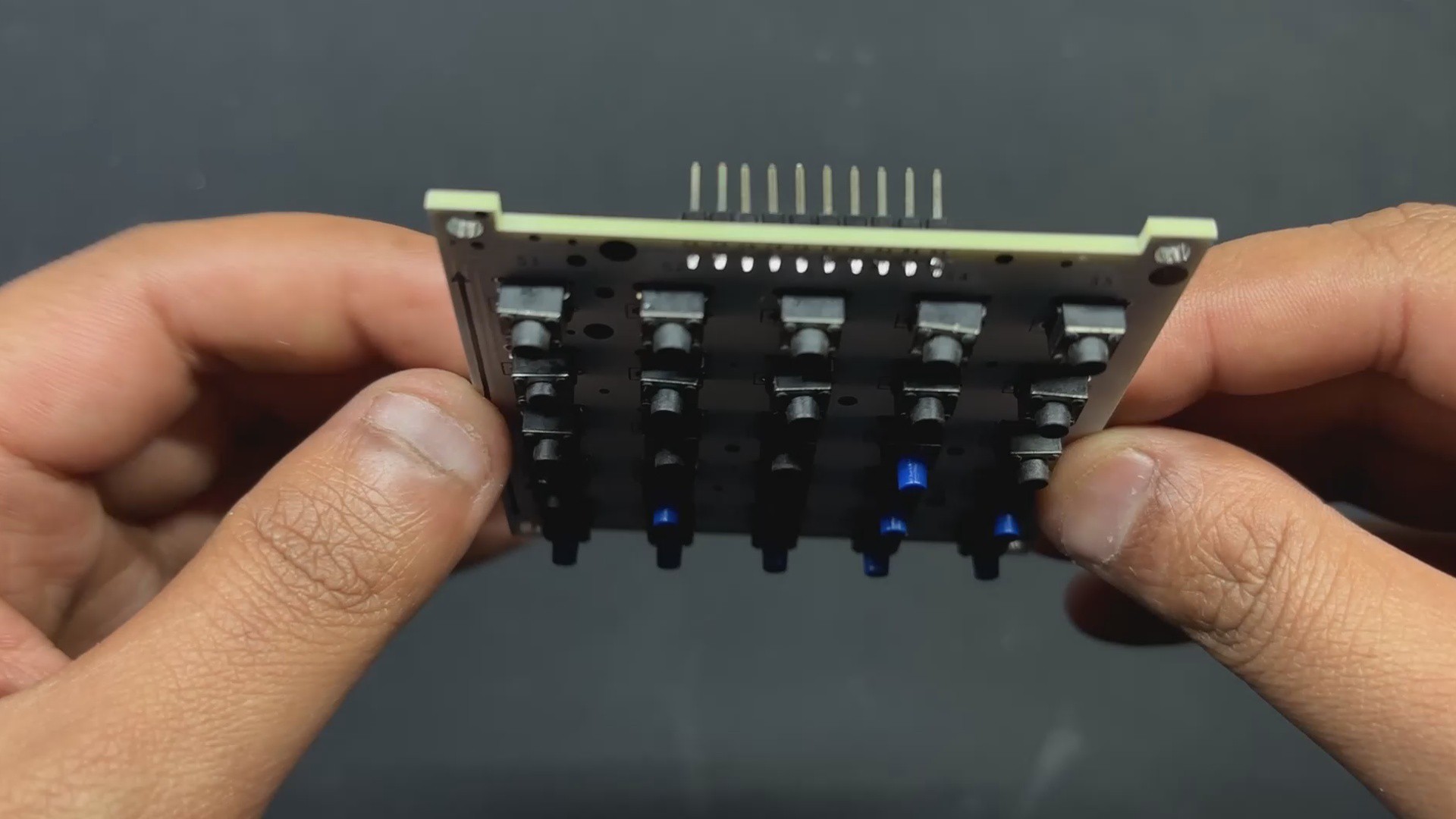
Discussions
Become a Hackaday.io Member
Create an account to leave a comment. Already have an account? Log In.