Mechanical switches such as push buttons or slides are great and offer simple on/off functions for a circuit, but they can be too big or a poor solution if you need a hidden type button. Tactile switches offer extremely small for factor, but they are momentary switches, meaning you have to hold and press them to activate and they turn off when you release (or vice versa). This tutorial will explain how to use a tactile momentary switch and make it act like a mechanical on/off switch, meaning press once to turn on, press again to turn off.
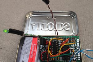
Mechanical Switch Example:
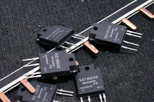
Tactile Switch Example:
This is written by a beginner for beginners. I spent a lot of hours scouring search results for an easy tutorial or explanation for how to turn a tactile switch into a momentary switch and found a lot of incomplete explanations, half tutorials, or things that explained the concept but were missing clear schematics.
Extremely Basic Explanation of D-Type Flip Flops
A flip-flop is a small circuit that controls the flow of power between pins. When one pin gets power, the circuit switches it to another pin, making the power "flip-flop" between them.
In the circuit below the power is entering the clock pin, and going to non-Q. (the Q with a line), . The LED stays off because non-Q is not connected to anything except D. We would need power coming out of Q for it to turn on.
When the switch is pressed it sends a signal to the flip flop which changes the power going through the circuit from not-Q to instead feeding out of Q. Because power is coming out of Q now the LED turns on.
I'm not going to draw you a logic table or go into more detail than that. YouTube actually has a ton of great videos on this subject if you want to understand more about how flip flops work. This section is meant to give an extremely basic layman's understanding of what a flip flop is flip flopping (please don't come for me).
Making the Circuit Using Actual Parts
It's a little tricky finding D-type Flip Flops that are as simple as in my diagram above. Normally you have a couple of extra pins.
The flip flop I picked (74LVC1G74DP) had the following pins:
- 1 CP: Clock pin, used to get the signal from the switch
- 2 Data Input: Used to dead in the signal into not-Q so there's an "off" state
- 3 Not-Q
- 4 Ground
- 5 Q: Used to feed power to the LEDs when active to create an "on" state
- 6 Reset
- 7 Set
- 8 VCC (power)
The data sheet describes this device as:
The 74LVC1G74 is a single positive edge triggered D-type flip-flop with individual data (D), clock (CP), set (SD) and reset (RD) inputs, and complementary Q and Q outputs. Data at the D-input that meets the set-up and hold time requirements on the LOW-to-HIGH clock transition will be stored in the flip-flop and appear at the Q output. Inputs can be driven from either 3.3 V or 5 V devices. This feature allows the use of these devices as translators in mixed 3.3 V and 5 V environments.
If we simplify that means: When the clock signal switches from LOW to HIGH (such as when the switch is pressed), the flip-flop stores the input from D and sends it to Q (taking it from our dead end in not-Q and moving it to the pin our LED's are connected to which is Q).
From there it was a matter of connecting my circuit like my previous diagram:
Let's break it down:
1. This is the ground, the negative side of my battery. This is also the metal pad you see labeled "-" on my board,
2. The resistor helps pull it LOW as well, and is a larger value, I used a 10K resistor.
3. Because the Flip Flop is described as LOW to HIGH, we need to have the 1 CP (clock pin) connected to ground (LOW) to keep it in active and having it feed the power into the non-Q pin that's our dead end. One side of the switch is connected to the ground (LOW) part of the circuit and the 1 CP (clock pin), the other side of the switch is tied to VCC (power/HIGH), so when it is pressed it send a HIGH signal to 1 CP (clock pin). This tells...
Read more » Smalls


 colinta
 Yann Guidon / YGDES
 Christoph
I’m not exactly sure why you decided to come “well actually” my article. 🤷♀️
There’s a ton of different switches out there that do a ton of things. Capacitive sensors wouldn’t work for what the end product of what I’ll be using these learnings for and they may not work for everyone’s use case either.
I guess thanks for sharing semi-related technology for a semi-related use.