 Jeremy
It moves!
It's not pretty, but it works! The movement is a little bouncy. After recalculating things, it appears that the coils are too wide, which likely causes the magnets to be slightly out of alignment (more on that later) and causes the movement to bounce.
General Actuator Design
I adapted the design from a thesis from Texas A&M titled "Design and Construction of a Precision Tubular Linear Motor and Controller" (source).
In the design, there is a tube (the pusher) filled with pairs of permanent magnets, with like poles facing each other ( NS-NS—SN-SN), and a spacer between them. The magnet pairs repel each other, yielding greater magnetic field intensity.
The pusher is moved by six coils, divided into 3 phases: A, B, and C. The second coil of each phase is in reverse magnetic polarity. We denote this with an apostrophe added to the phase labels: A', B', and C'.
For example, coils A and A' are connected to the same power output, but the wires of A' are connected in reverse. Both will always have the same current flowing through them, but their magnetic fields will be in opposite orientations.
A part of the thesis that I spent way too much time re-reading was this gem:
"the pitch of six magnets with six spacers is 63.30 mm, twice the pitch of two magnets with one spacer"
I'm not sure why it was worded this way, but it's basically saying: "three coils + three coil spacers = two permanent magnets + their spacer".
This is the pitch and ensures that the magnets aligned in A/B/C are arranged the same, but opposite polarity, in A'/B'/C'. If the pitch is different, the movement and force will be affected. This is likely why my current version has bouncy movement and low force.
Moving the pusher
The current is shifted from one coil to another to move the pusher. To calculate the current for each movement step, we generate a sine curve for each phase at 120 degrees apart.
As I understand it, here's how it looks when moving the actuator pusher.
[EDIT: I might be off on how the stepping works, below. I discuss that in my next post]
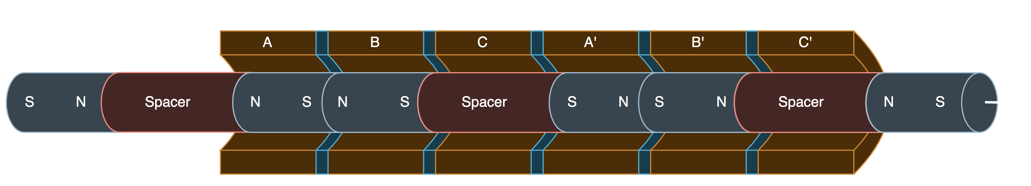
Step 0°
The first step
At this step, phase A and A' are at 100% and -100% current, respectively. The other phases are at +-50%. In this case, the pairs of magnets are centered under A and A'.
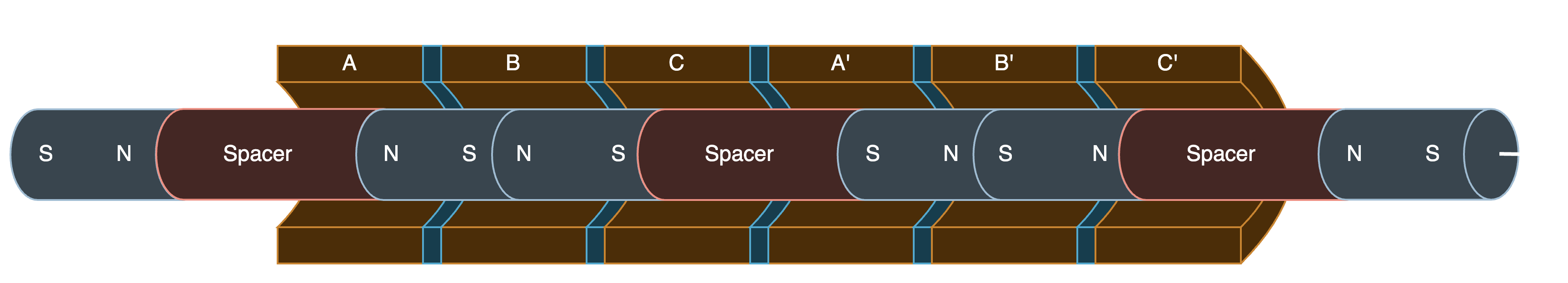
Step 60°
Now, A/B phases are at +-50%, and the magnet moves to the right to center between these two coils.
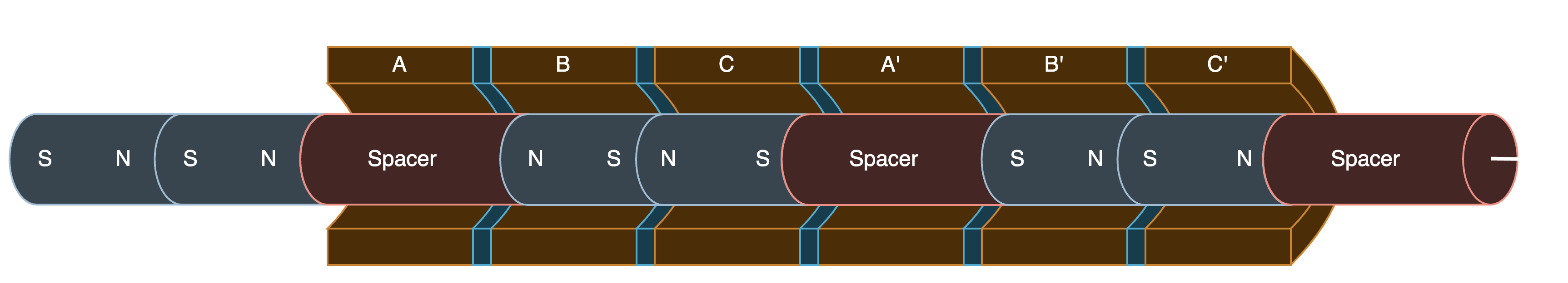
Step 120°
B is at +-100%, and the magnets move to be under it.
Step 180°
Phases B & C are at +-50%, and the magnets move to be centered between these two coils.
And so on, and so forth, to continue moving the pusher.
My Linear Motor
Dimensions
My version of the linear motor is much smaller than the one in the thesis I'm basing it on. Here are my part dimensions:
- Magnets: (see note below) 6.35mm long, 4.7625mm diameter
- Magnet spacer: 4mm long
- Pusher tube: 6mm diameter carbon fiber tube.
- Coils: 3.6mm wide -- should have been 2.6 mm wide!
- Coil spacer: 0.8mm thick
- Wire: 36 AWG
NOTE: For the magnets, instead of pairing up magnets between spacers, I used a single 6.35mm magnet. This made assembly slightly easier, and they should work the same. In this configuration, the pitch would be calculated as one magnet + spacer = 10.35mm.
Circuit
To drive the coils in both polarities (bipolar coil), we drive each coil with an H-bridge motor controller.
I used three L9110H H-bridge motor drivers, one driver per coil. These drivers have two inputs and two outputs.
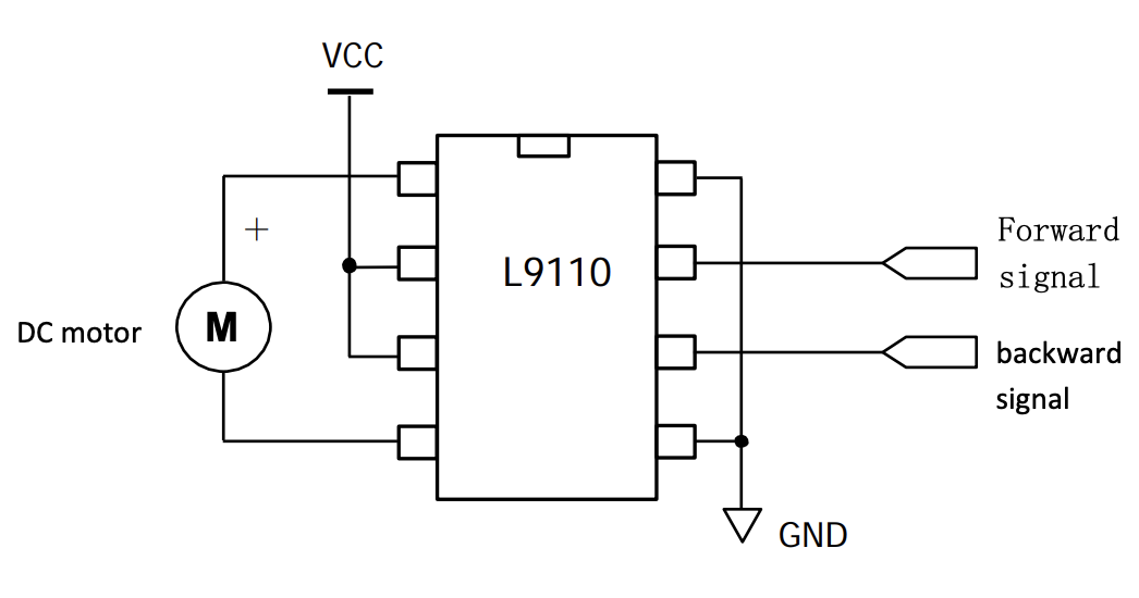
The outputs are connected to the wires of single-phase coils. The driver inputs determine the polarity of the output.
| Input A | Input B | Output A | Output B |
|---|---|---|---|
| High | Low | High | Low |
| Low | High | Low | High |
| Low | Low | Low | Low |
| High | High | Low | Low |
Microcontroller
At the center of the circuit is a microcontroller running CircuitPython. Each motor controller is connected to two of the microcontroller's PWM outputs.
Here's the code I used: https://github.com/jgillick/tubular-linear-actuator/blob/main/code/circuitpython/sine/code.py
Discussions
Become a Hackaday.io Member
Create an account to leave a comment. Already have an account? Log In.