 Nikhita
What’s toasting?! This week, we focused on our initial construction and electronics setup.
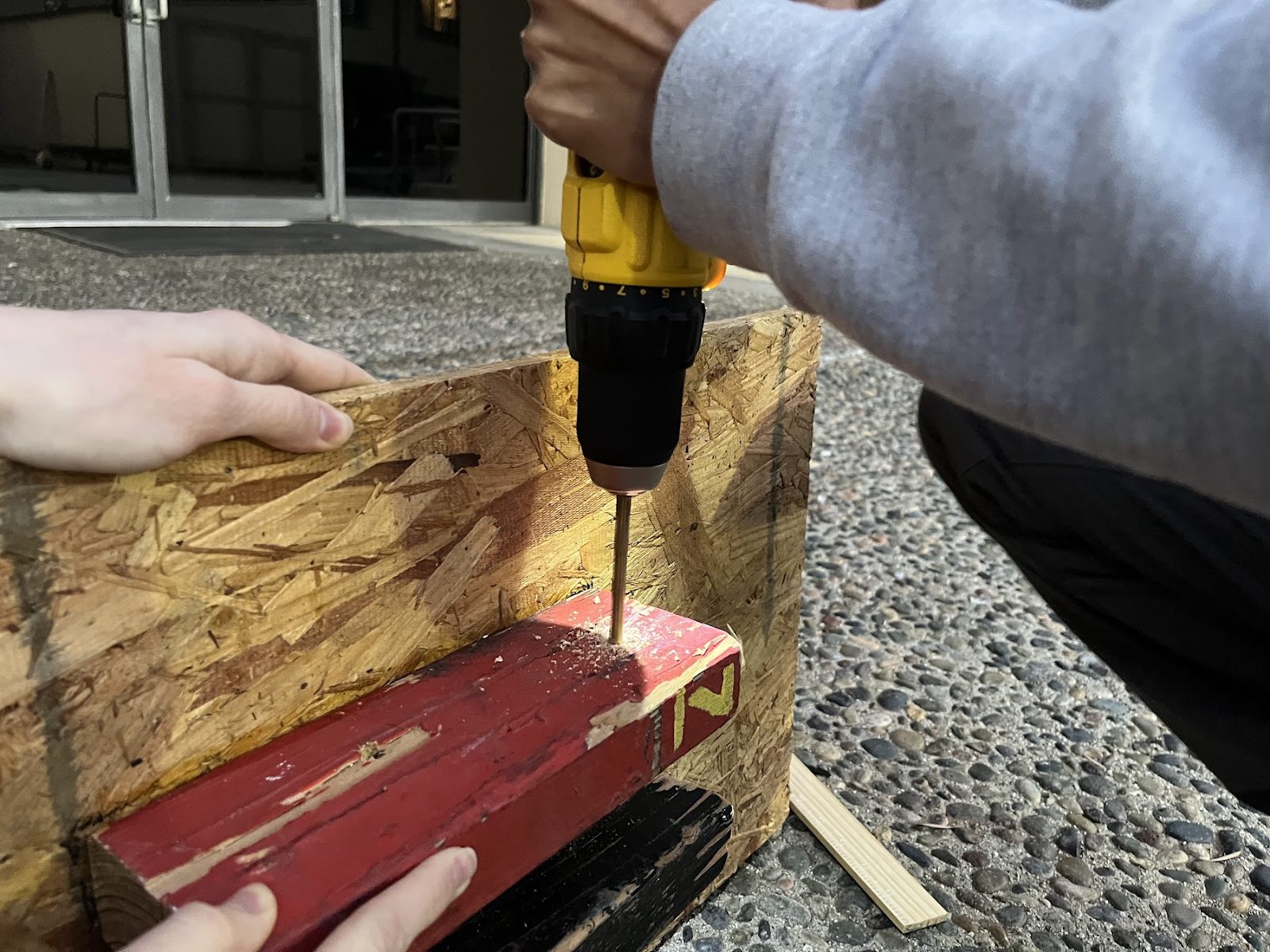
We obtained wood for construction and began gluing and drilling components together. We assembled the base beams, vertical beams, and both axles.
We also decided upon the following additional design considerations:
- Place the base beams as close as possible (increase the flexural stiffness of the 2 axles—shorter beams are less prone to buckling and deformation)
- Place spring to the arm as far away from the pivot point as possible (maximize torque)
- Place axle 1 as low as possible to decrease force experienced upon impact with arm
- Place solenoid as far away from pivot point as possible (maximize torque)
- Make the arm as long as possible (maximize angular acceleration of bread!)
- Use a 6-pointed servo (maximum area of contact on flat peice)
- Make the hole for axle 2 larger than holes in vertical beams (so arm freely rotates & beams are locked by servo motion)
- Cyborg arm (“Bucky”/”Winter soldier”) with bottom half (hitting axle) comprised of wood 12in, and top half 3D printed (reduce weight, increase angular acceleration, easy replaceability)
- Balsawood cuts for servo 1
- Have the piece attached asymmetrically to servo 1 (maximize torque)
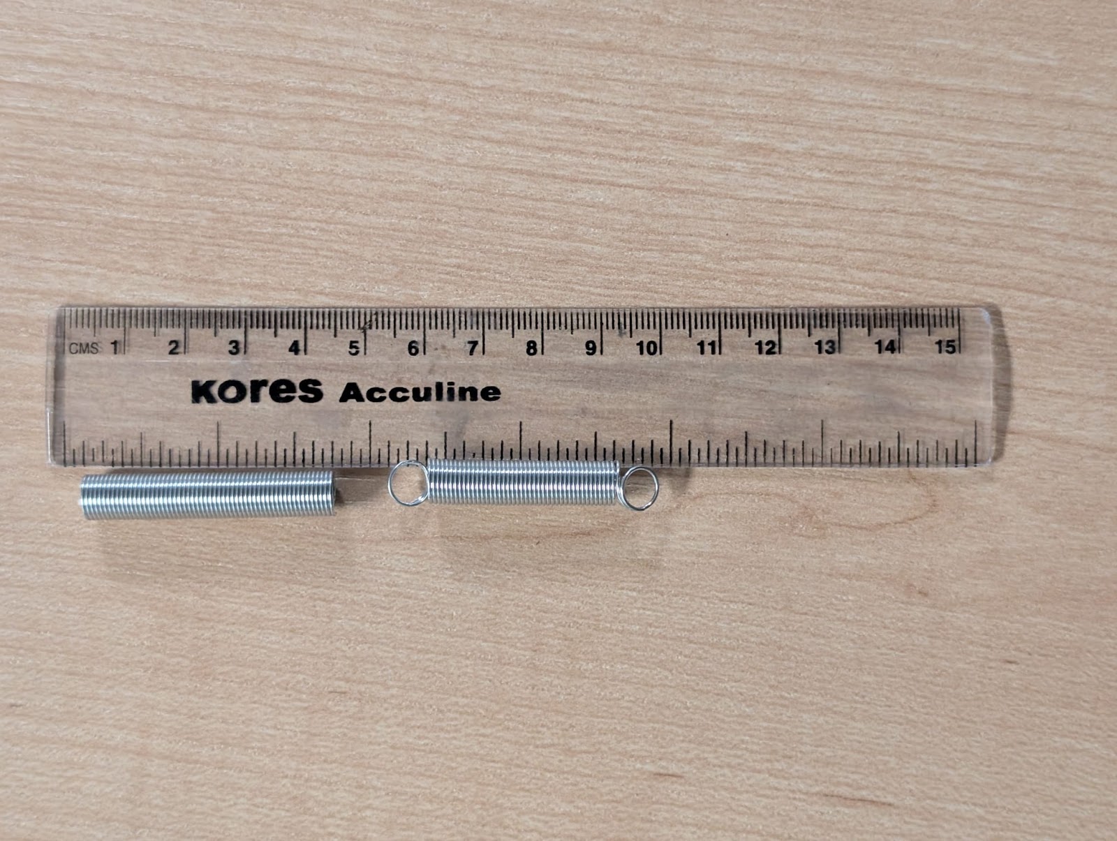
- Springs that we’re considering
On the electronics side of things, we were able to pick up our servo motors, potentiometers, buttons, and other various components. We began coding, and after a few minor setbacks (rip to the smoking potentiometer), we were able to complete the code for Servo 3 (which controls the vertical beams) and begin working on implementing Servos 2 and 4, which hold down the arm as the spring extends.
 Em“chk”ily, Ka“chk”te, Nik“boom!”hita
Discussions
Become a Hackaday.io Member
Create an account to leave a comment. Already have an account? Log In.