0%
0%
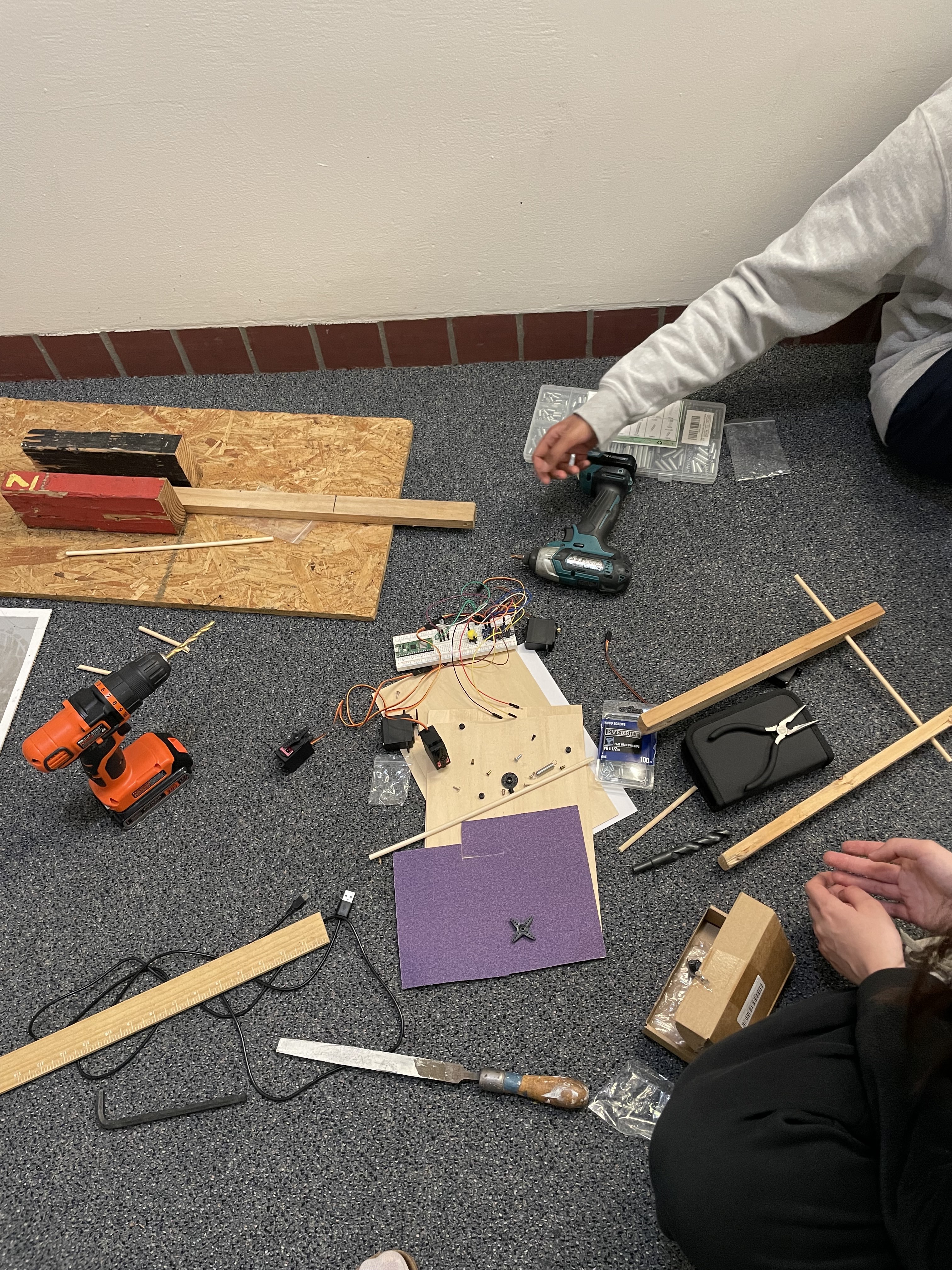
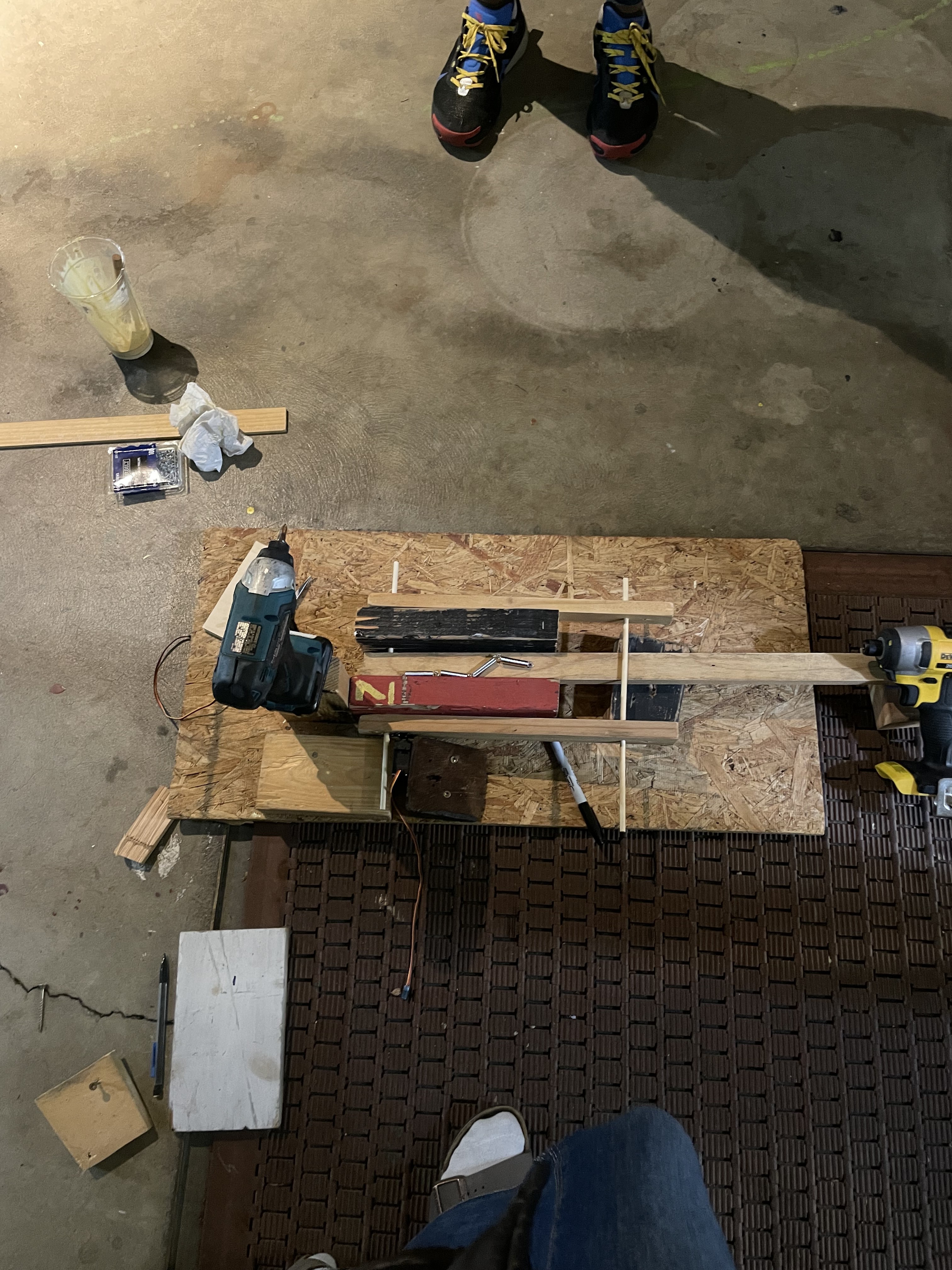
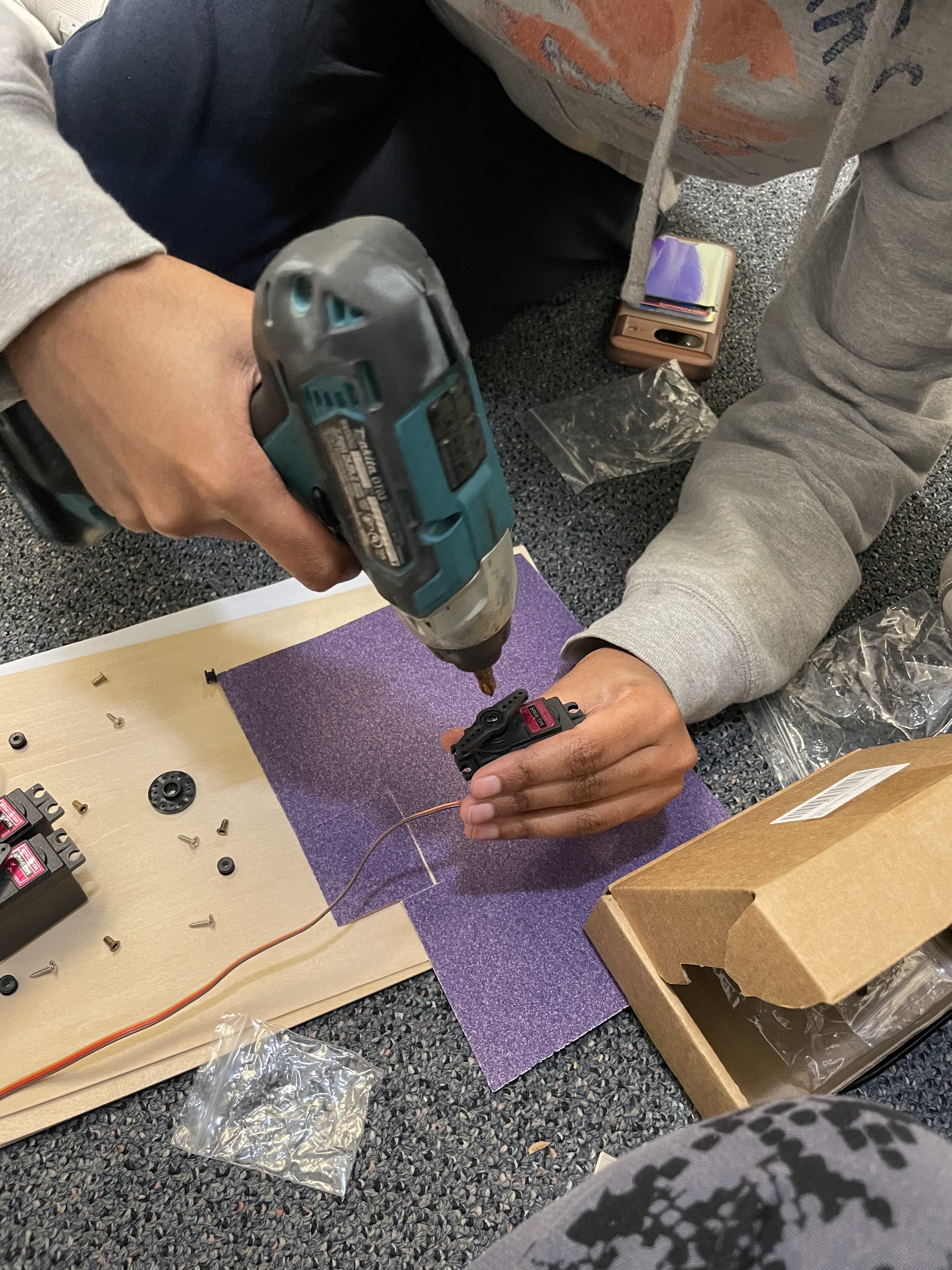
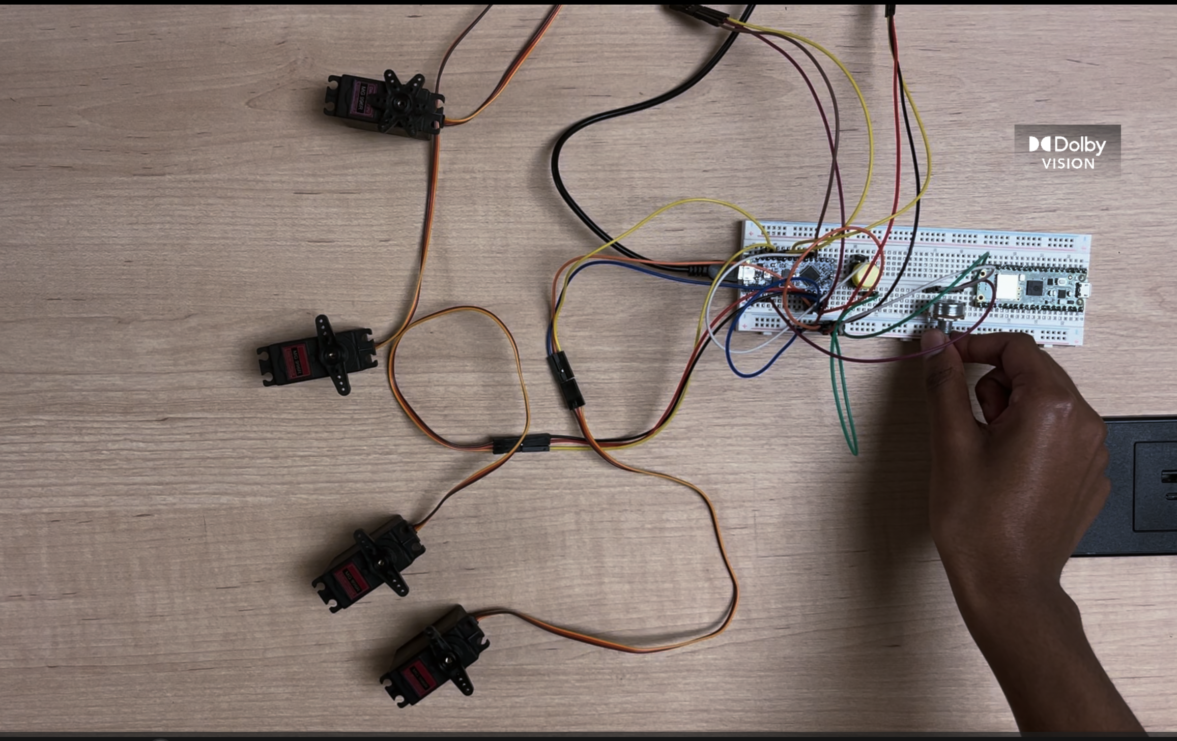
Breadapult
3 servos. 1 arm. Infinite destructive ability.
 Emily
EmilyBecome a Hackaday.io member
Already have an account? Log in.
Just one more thing
To make the experience fit your profile, pick a username and tell us what interests you.
Pick an awesome username
hackaday.io/
Your profile's URL: hackaday.io/username. Max 25 alphanumeric characters.
Pick a few interests
Projects that share your interests
People that share your interests

 Em“chk”ily, Ka“chk”te, Nik“boom!”hita

 Mike Rigsby
 Nick Rehm
 Val
Val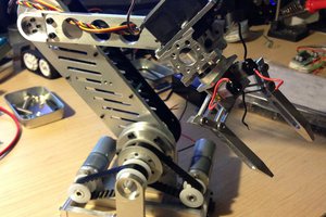
 CLo
CLo