mclien
-
1st prototype
01/27/2025 at 15:09 • 0 comments(still 2018)
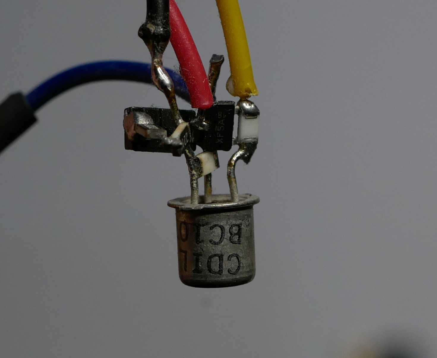
For the first prototype I used the parts as seen in the previous log (Adafruit: itsybitsy, DS3231 module, lipoly backpack) and I used a mix of THP and sdm parts to make the latching circuit "in the air".
Using a transistor as replacement for a pcb kinda works:
![]()
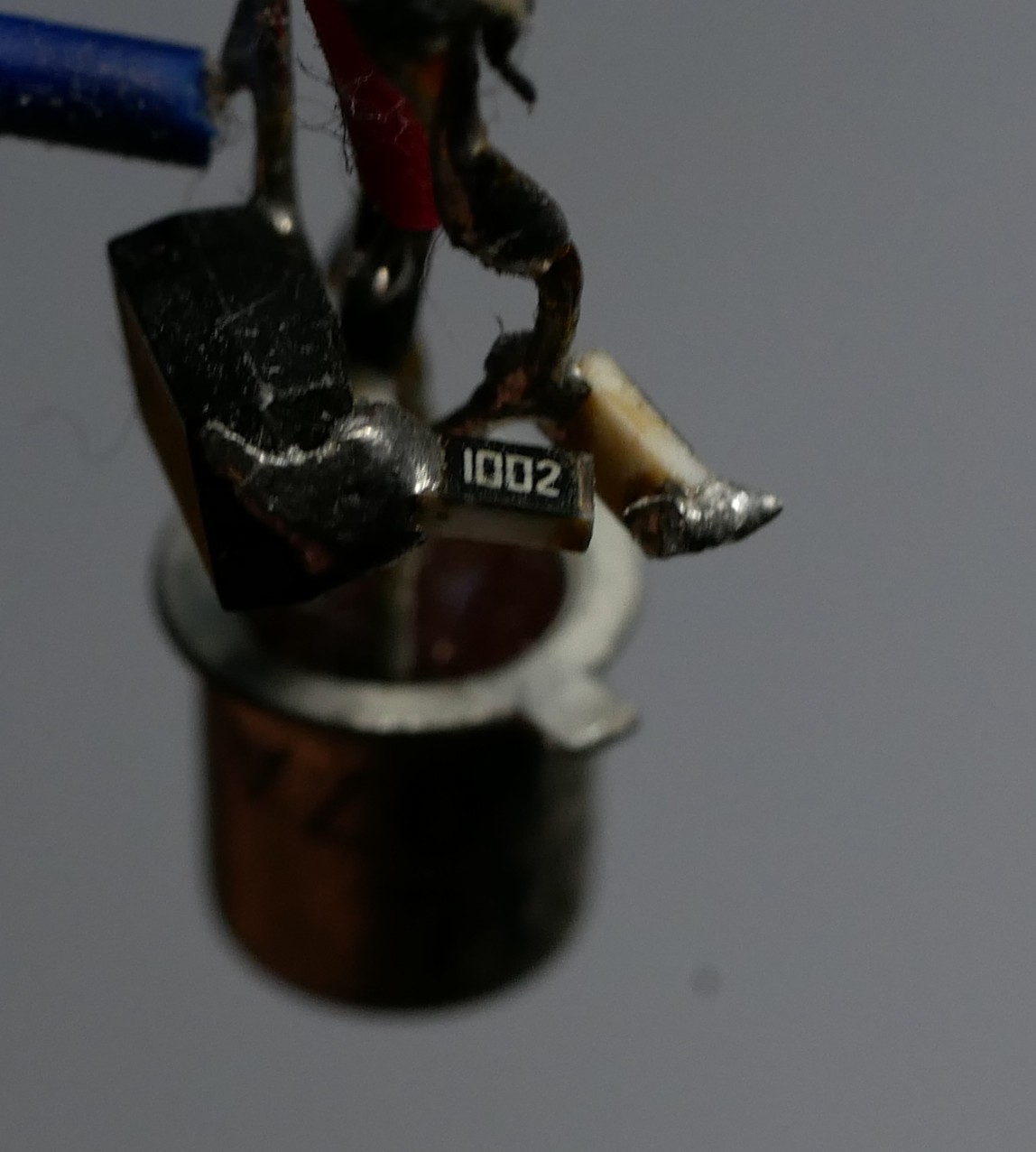
But is very fragile since the pcb usually hold together the smd parts.
![]()
Some minor drops on soft ground and the fakt, that I needed to open the case to reach the USB port for loading didn't exactly prolonged the lifespan.
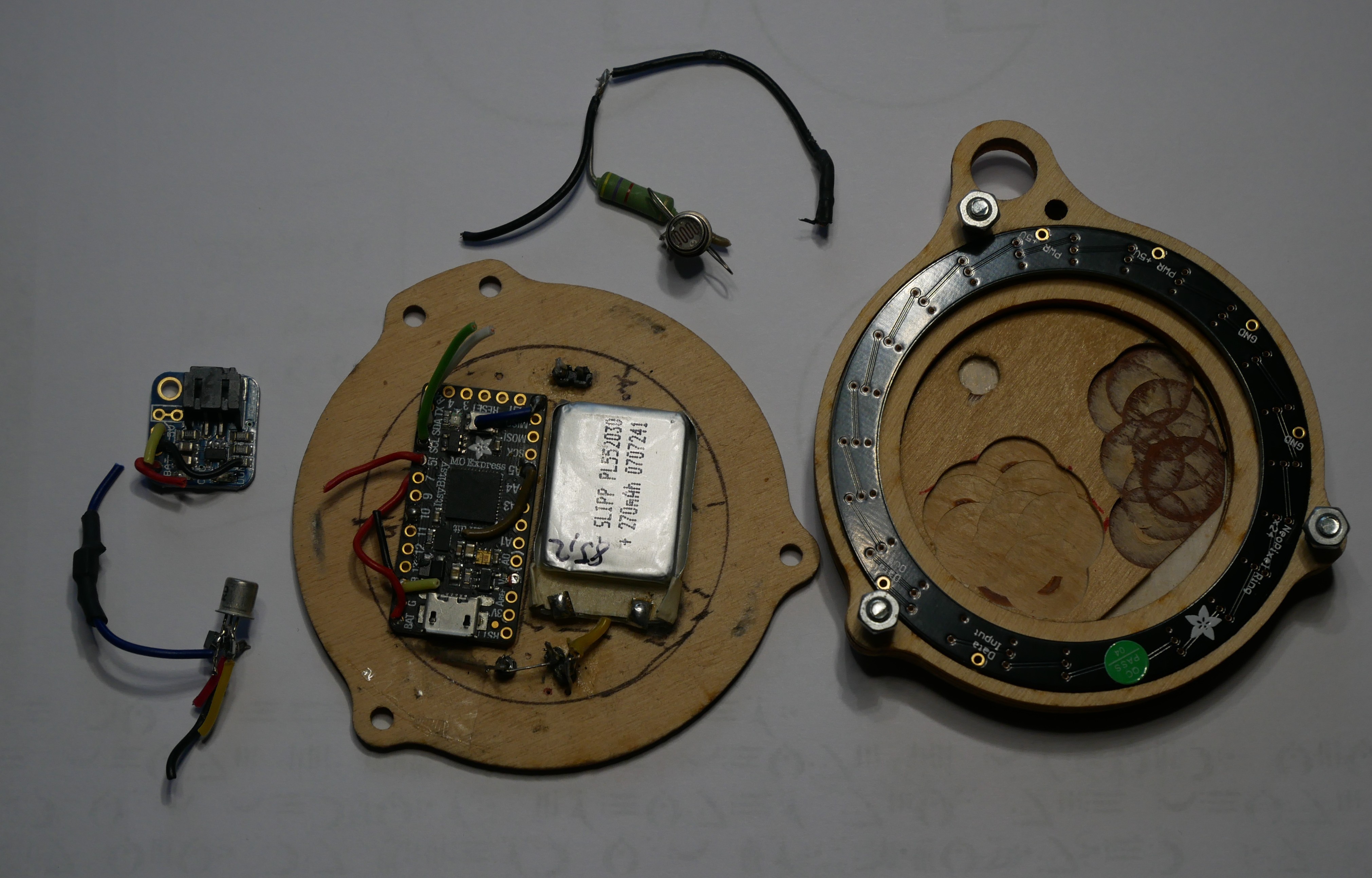
This is all I found from the first prototype with the RTC missing in the pic. I think I just stacked it somewhere on top. The RTC was on top of the ItsyBitsy and the air-solder parts somewhere in the leftover corners. And there was a LDR placed behind the veneer, which didn't work (maybe I didn't know about voltage dividers at that time):
![]()
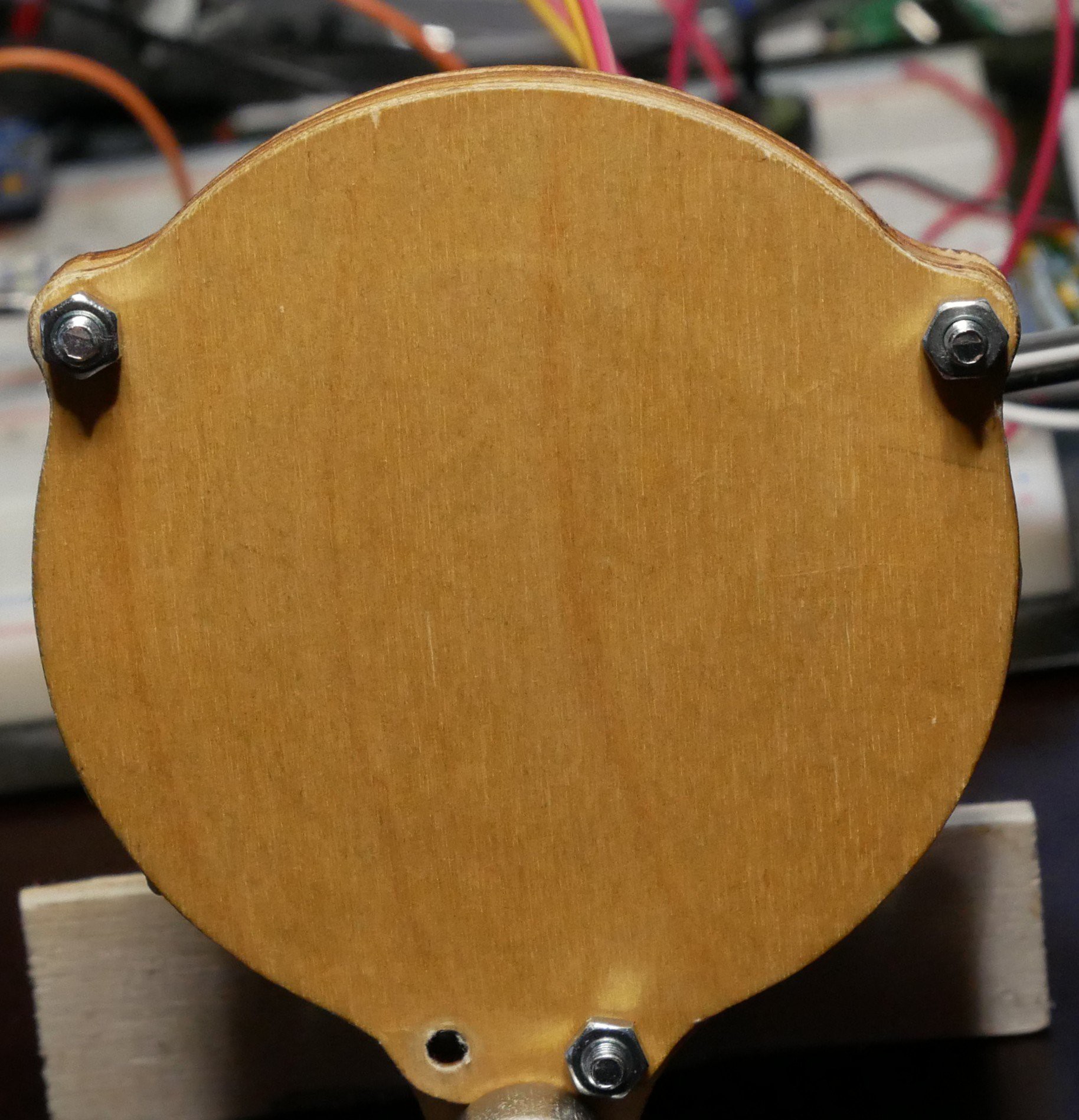
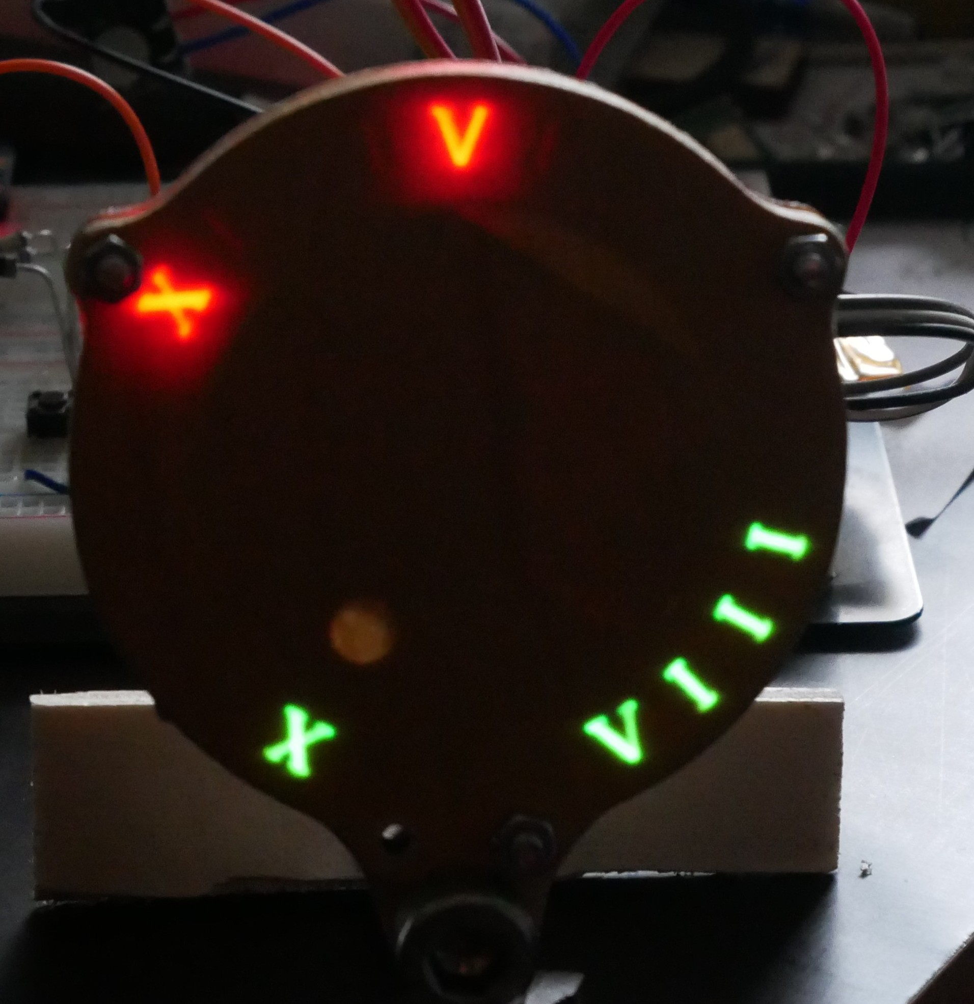
I covered the LEDs with veneer, which makes a nice effect, since in power-off mode no letter give away, what's hidden, but is unreadable in sunlight. Here are 2 shitty pics of that setup (faked it by wiring it to the new breadboard setup):
![]()
![]()
Also I tried to make the power on more obscure/magic by using a reed contact as power on switch and a hidden magnet in a silver ring. Still don't know if it was mainly lacking knowledge about read contacts or a bigger read contact/magnet combination is needed. I changed that to 2 blank wires sticking out of the back of the case, which I bridged with said ring (not much better either).
-
Block Diagram
01/26/2025 at 21:43 • 0 comments(still about 2018)
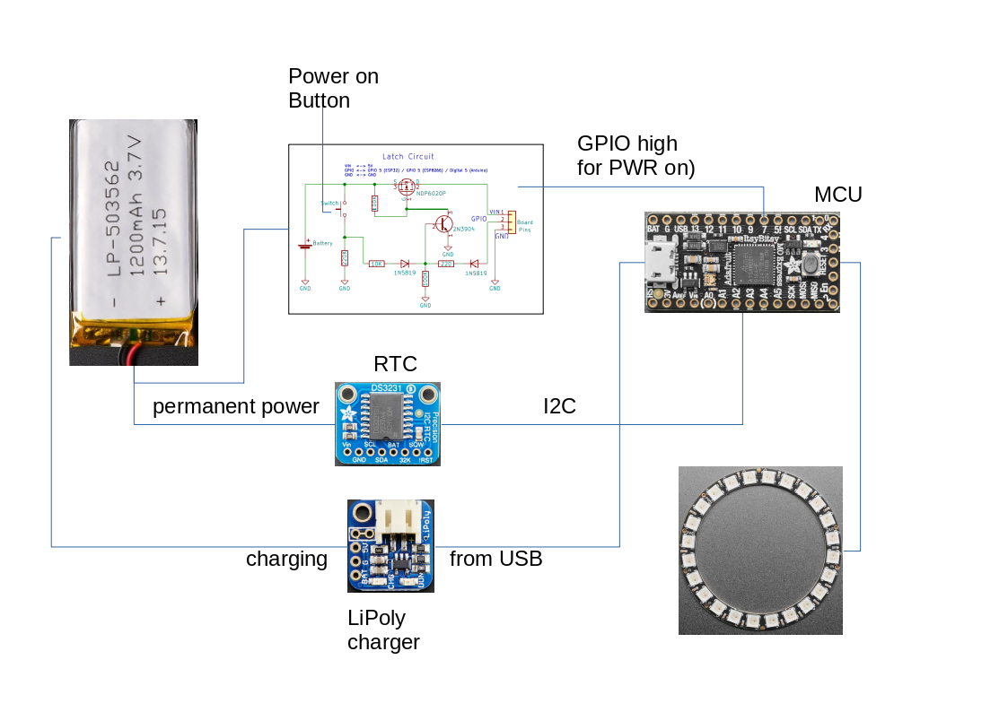
Basic elements elements:
![]()
The LiPoly battery, permanently powering the RTC and being connected to the Latching circuit and the charger.
The power push button switches on the MCU, which in the first line of the setup, sets a GPIO pin to high, holding the latching circuit "on", the MCU reads the time from the DS3231 over I2C and lights up the LEDs which assemble the corresponding roman numbers.
Whenever the MCU is plugged to an UBS power source, the battery is charged.
-
Watch face design
01/26/2025 at 20:59 • 0 comments(about 2018, I guess)
The first intention was just some watch with those runes as the numbers, not much more. As I was hosting the website for the makers of the comic, I asked them if it was just some random scribbling or if there was a design of a whole alphabet and numbers. Turned out it was an alphabet but no numbers. So they came up with the idea of using the Roman numbering system. As I wanted to have some "glow" affect, LEDs are somewhat inevitable.
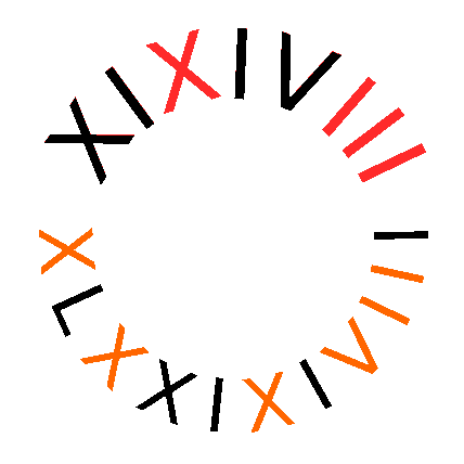
As the roman system uses lower values in front of higher for subtracting, the letters need to be sorted in a way, that all numbers can be displayed the resulting row looks like this:
XLXXIXIVIII for minutes, XIXIVIII for hours. You could of course use the common trick to Display hours an minutes sequential, but as I wanted something resembling a watchface, I went for "hours top, minutes bottom".
At this point I was of the impression that a minimum of 19 LEDs was necessary, which I'll proofed wrong later (will be in the according log)
Here is a graphic of the idea (displaying 13:37):
![]()
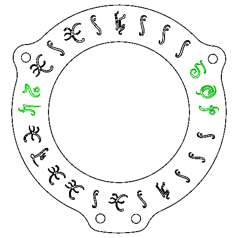
red "LEDs" for the hours, orange for minutes. Same with the runes from the comic:
(green ones are the spare 5 LEDs, which I filled with some of the other runes ( H,B for Humbug and Binky the makers of the comic, And TOP, Tales of Pylea, the name of the comic)
![]()