 mclien
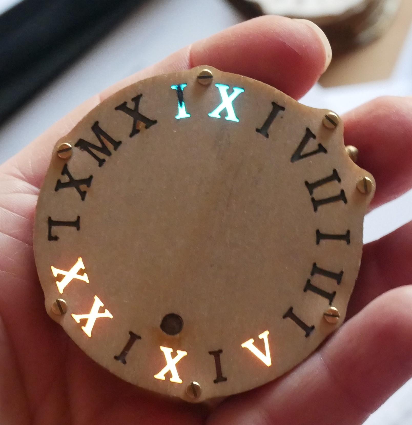
This deliberately a non-connected device, which tells the time only.
It all started with a new page of a favored webcomic of mine:
https://talesofpylea.com/top/index.php?site=157
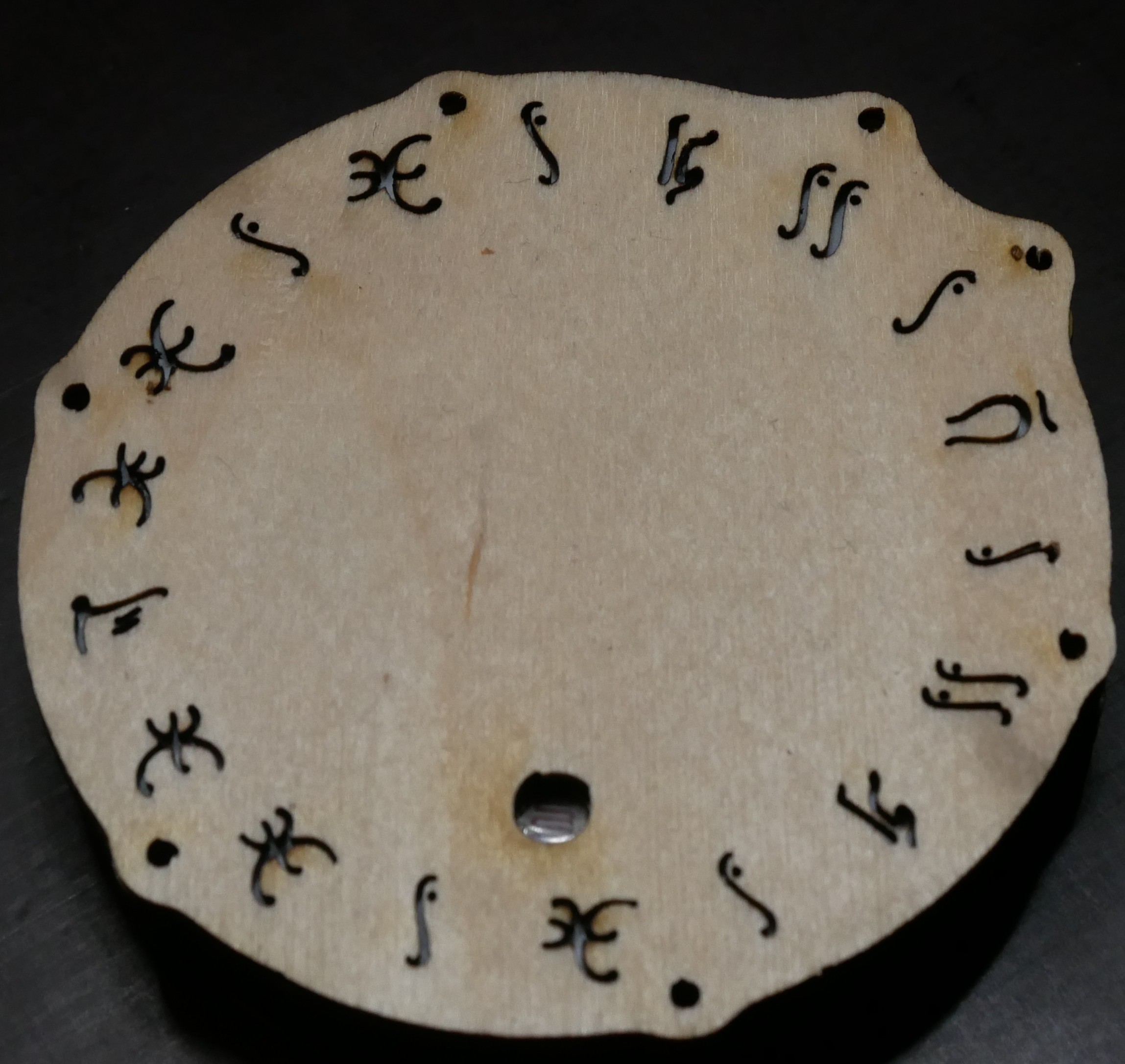
As I needed a time telling device, which could pass in Fantasy LARP Setup as some magical device which enhances your "feeling for time", I immediately wanted to make watch related to this design.
While this device in the comic is a Coffeemaker, I saw a watch.
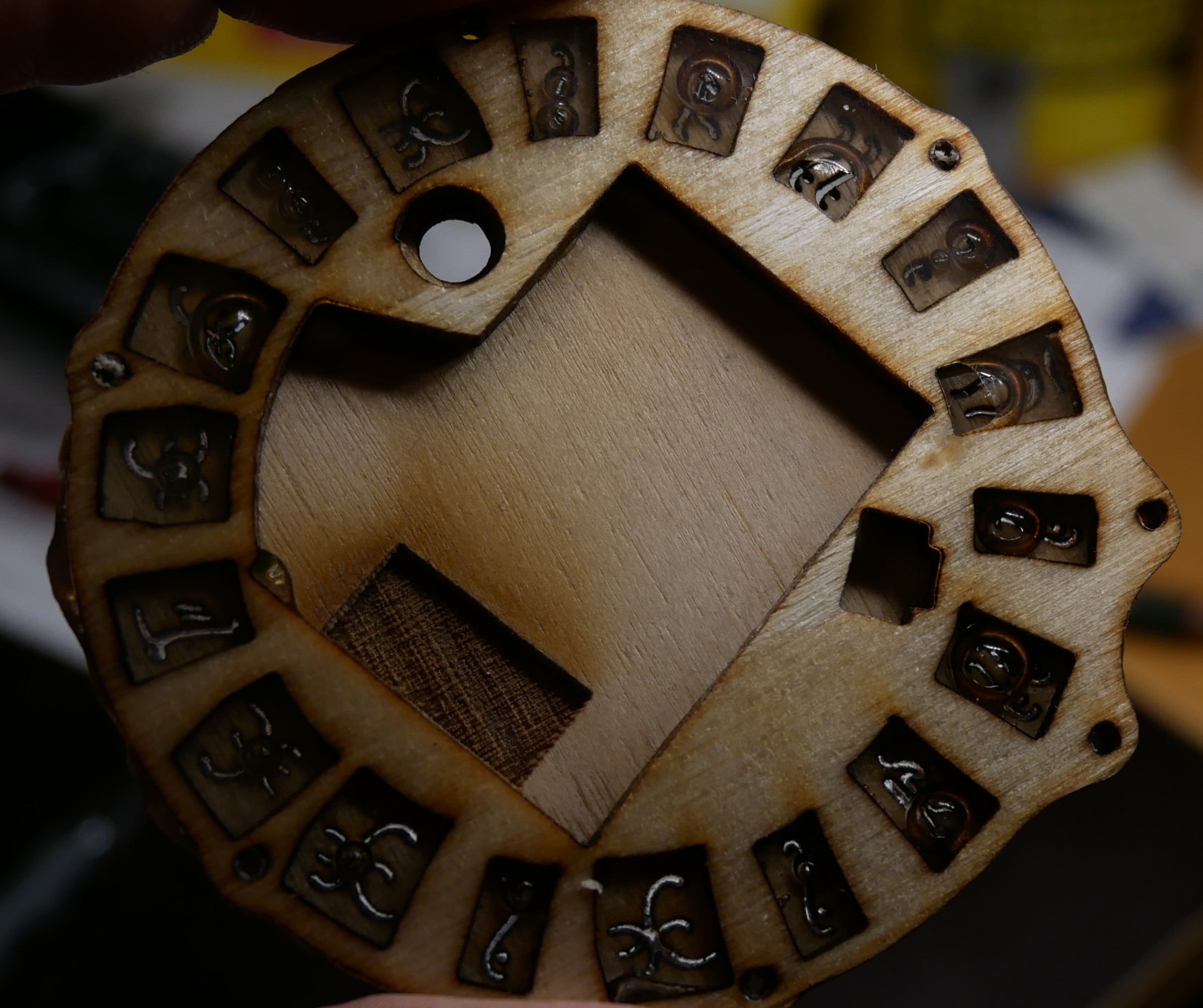
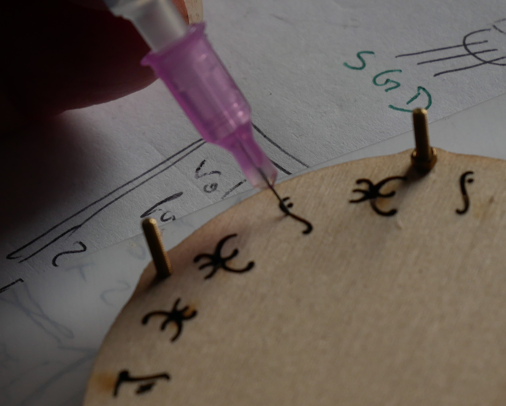
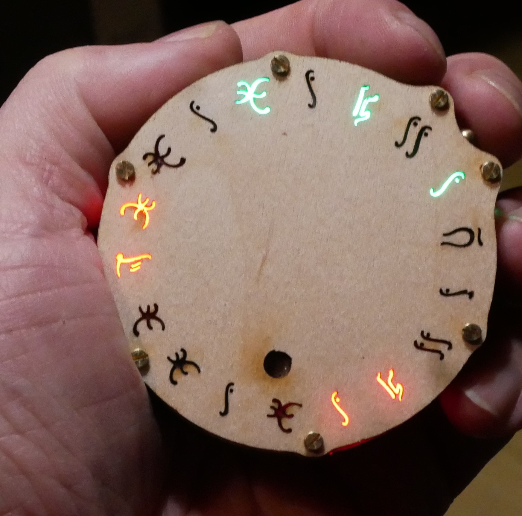
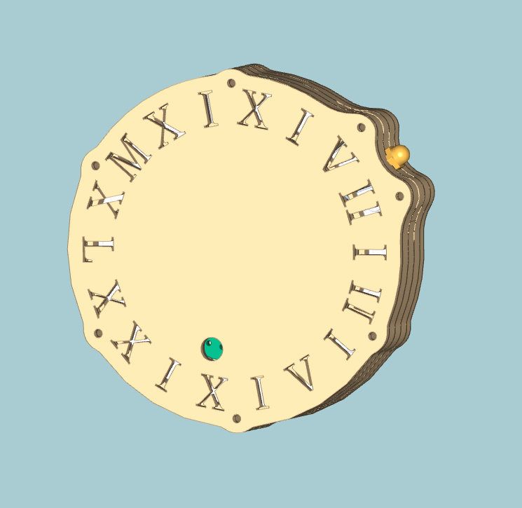
I figured out that 17 LEDs are sufficient to display time in 24h format, hence the name.
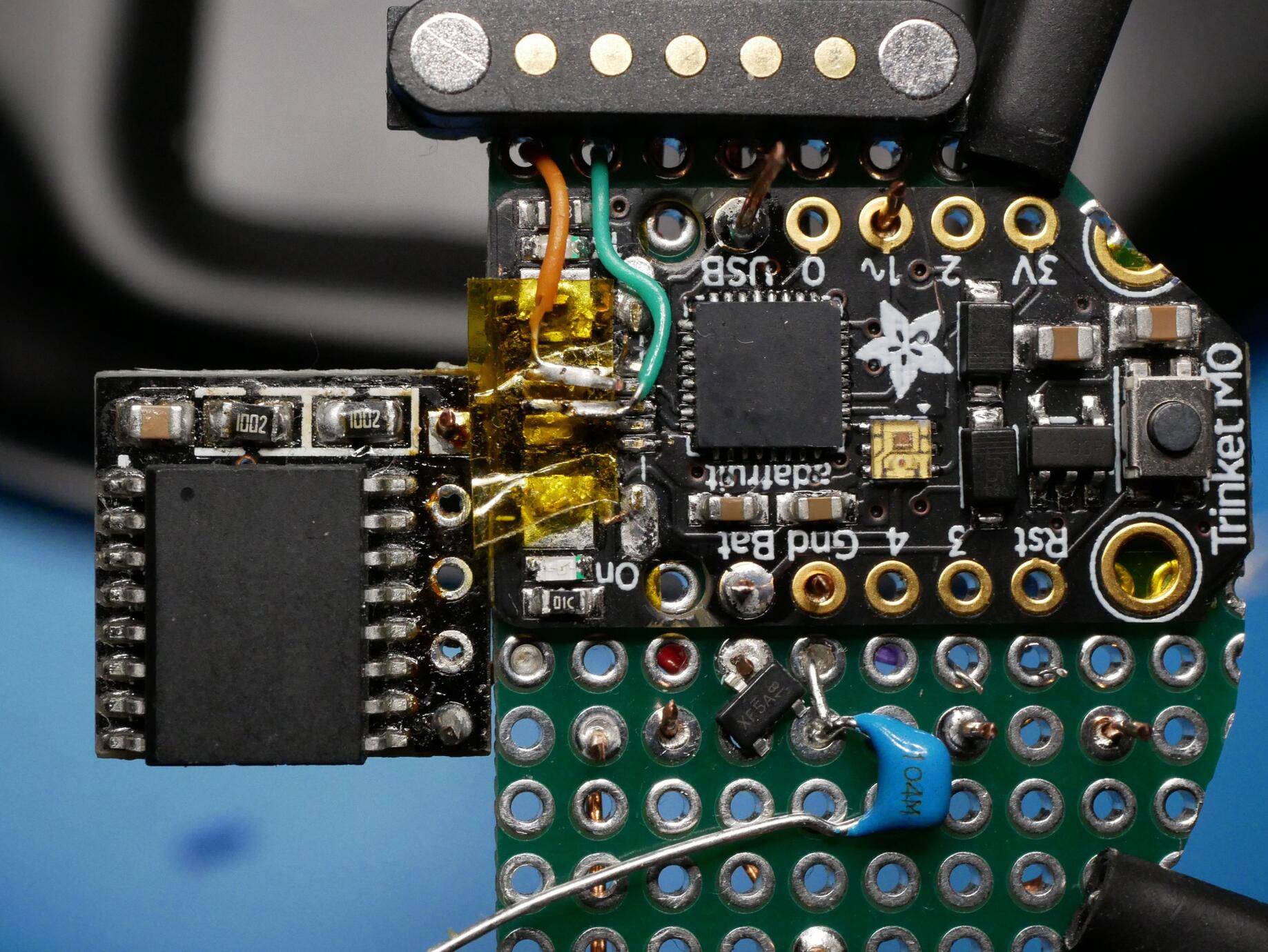
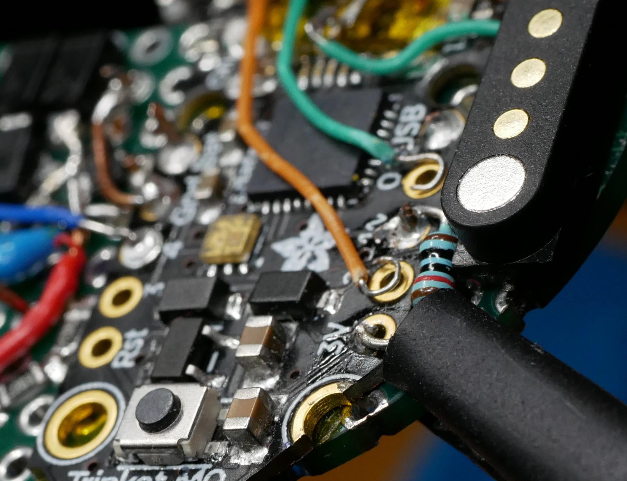
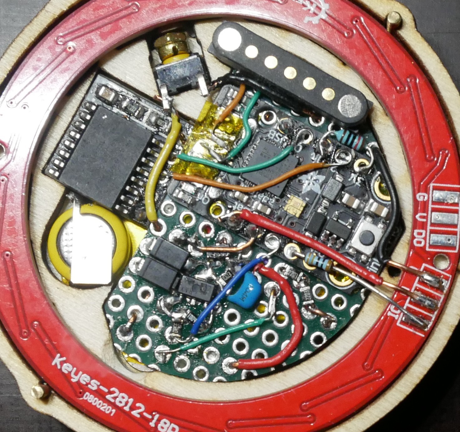
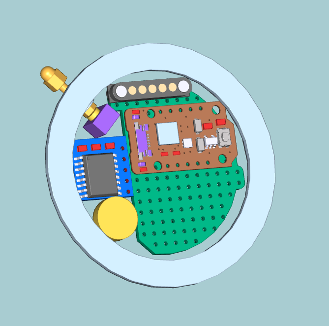
MCU:
for the moment I use a adafruit trinket M0 (ItsyBitsy for the first prototype).
The idea is to design a arduino board for general watchmaking purposes (will open an extra project for that one), perhaps reviving another project (idea) of mine:
https://hackaday.io/project/2528-smart-dcf77-wirst-watch
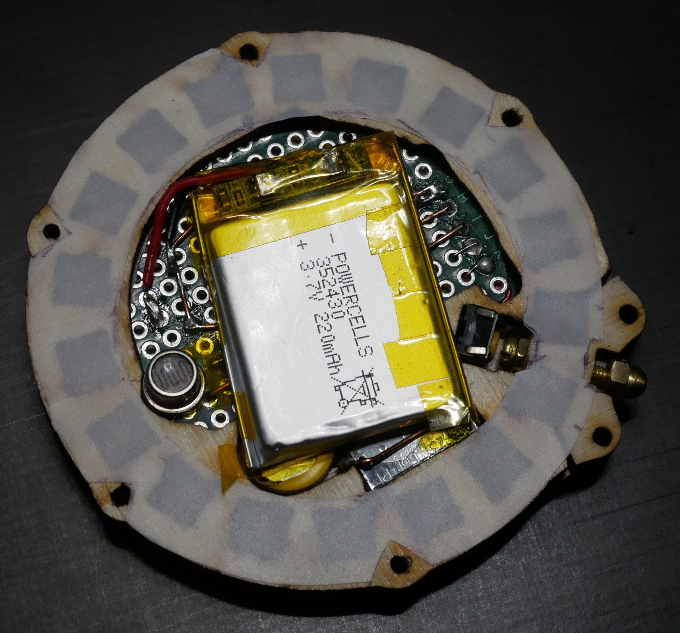
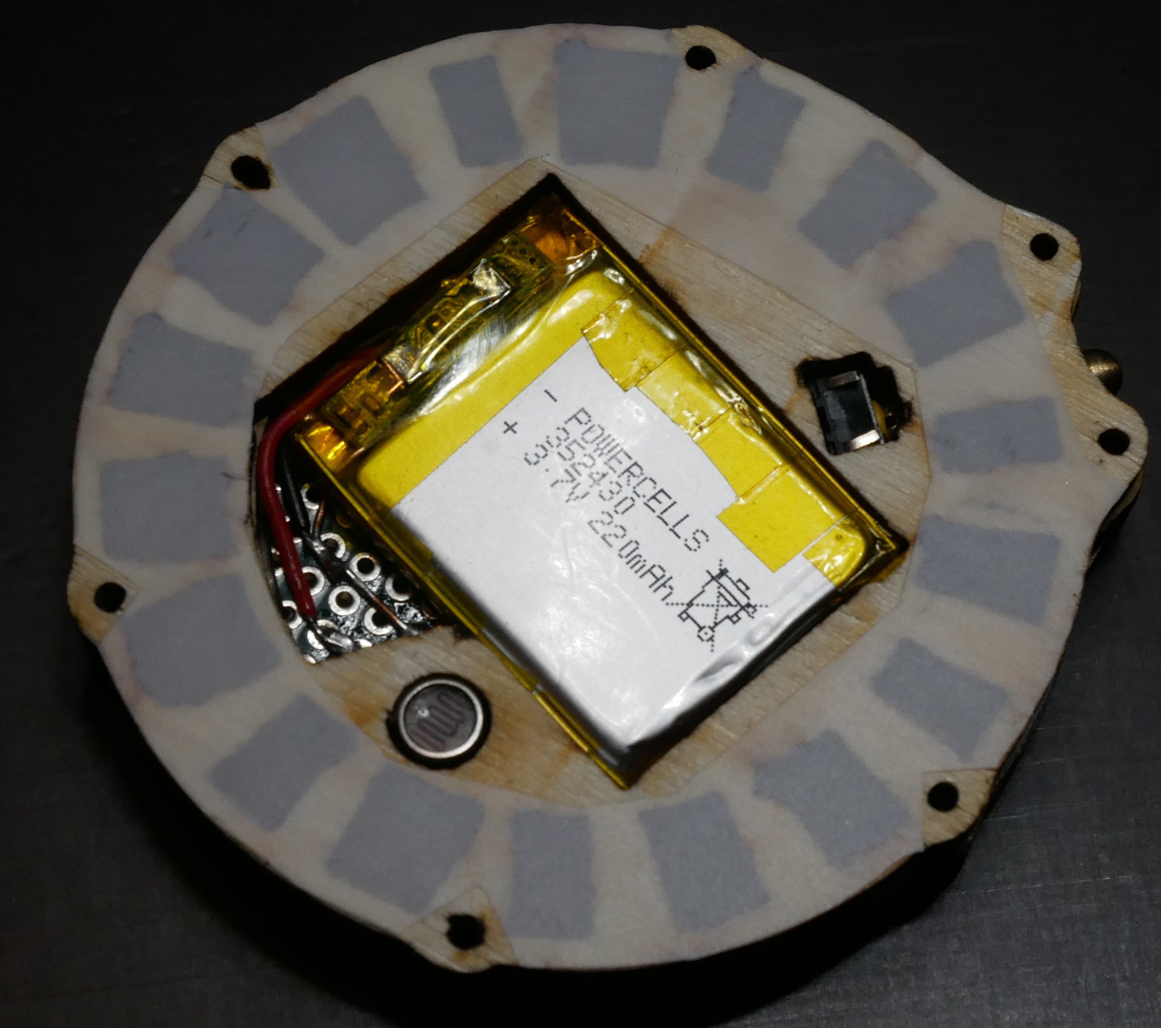
Power Latching:
I just picked one of those with mosfets and the potential of using the hold PIN as an input while powered up. This was my main guide:
https://circuitcellar.com/resources/quickbits/soft-latching-power-circuits/
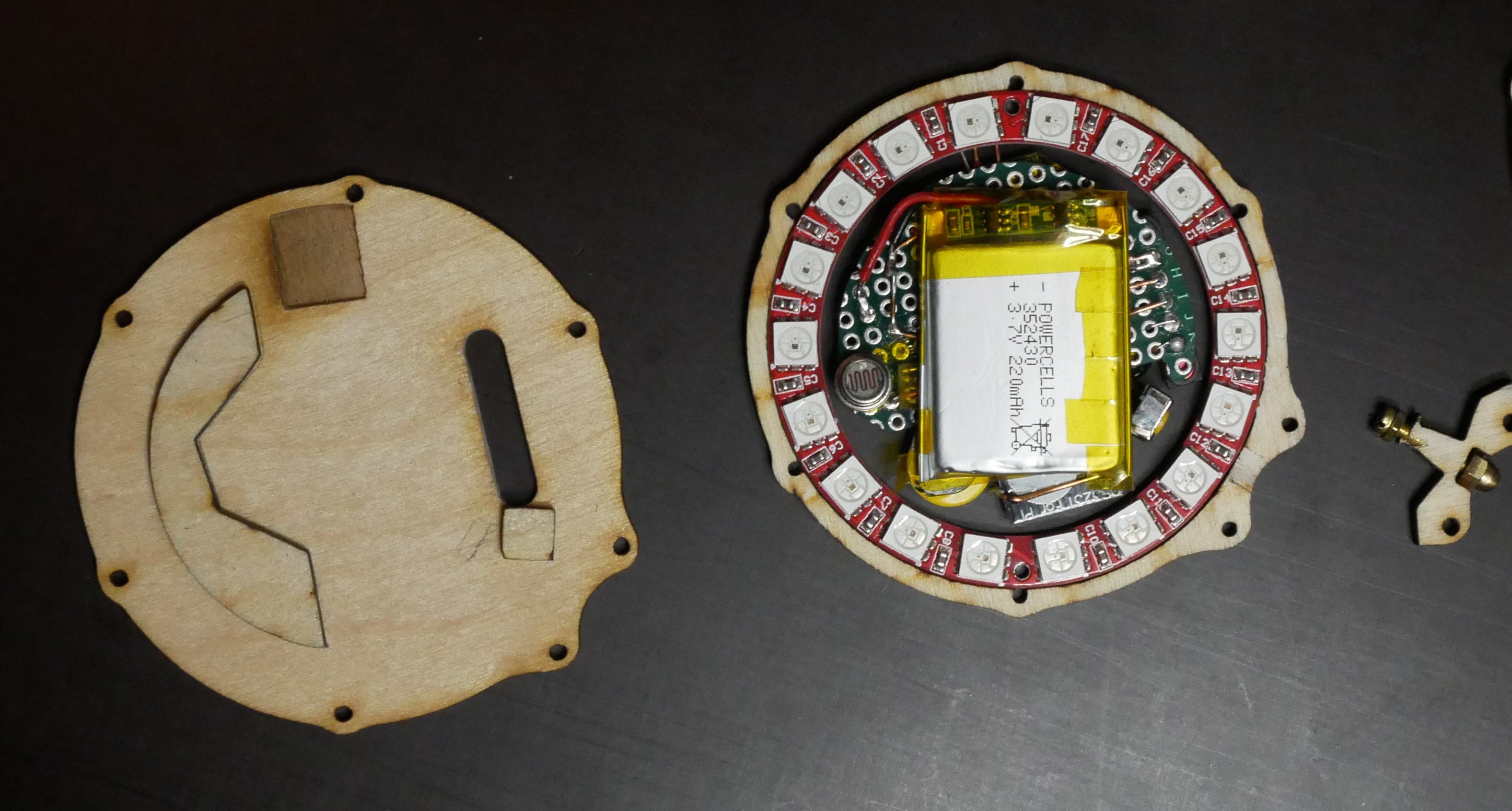
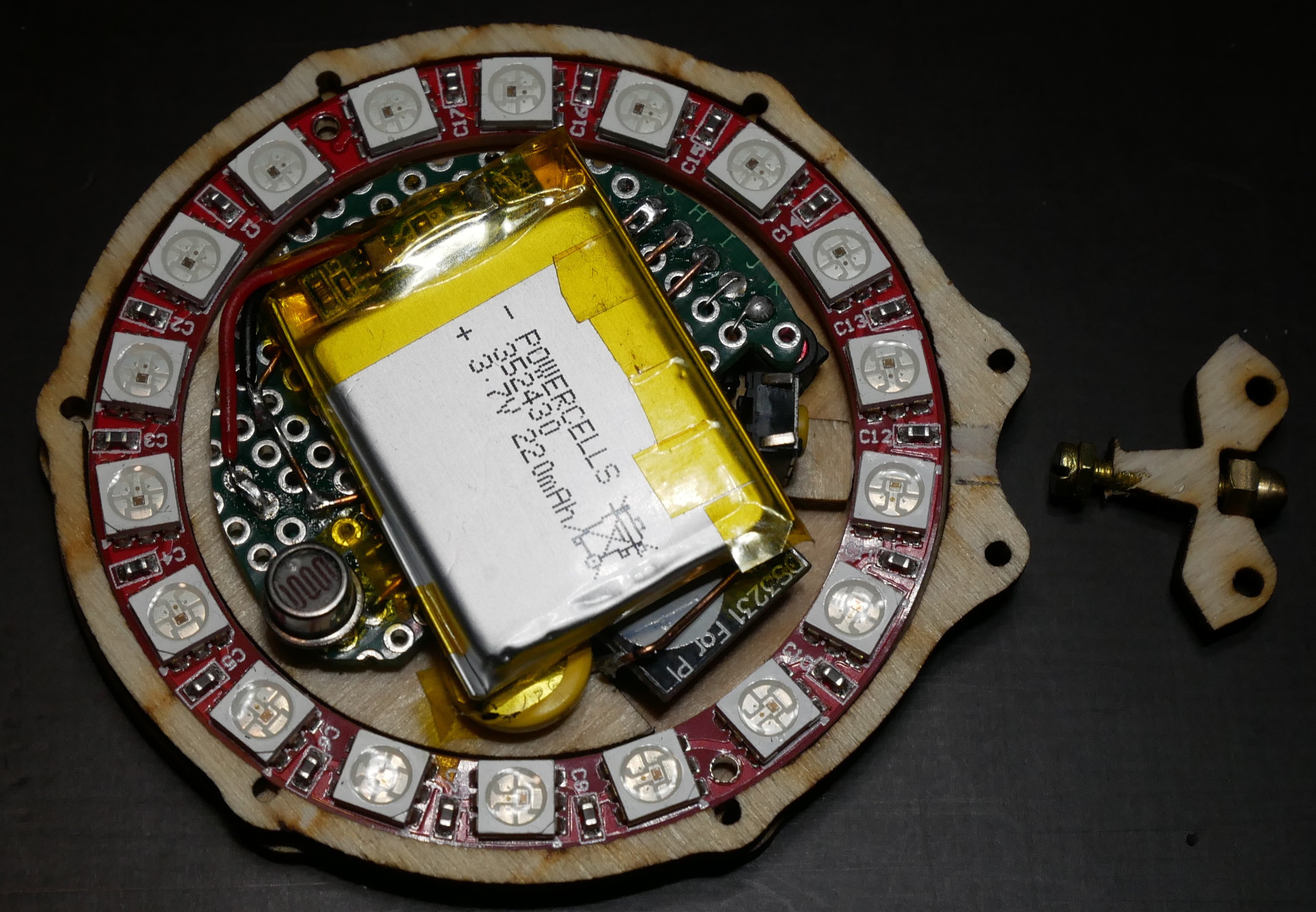
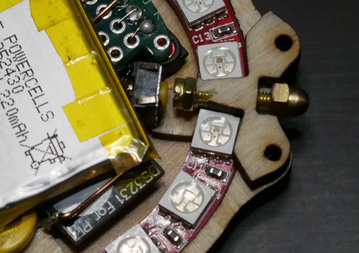
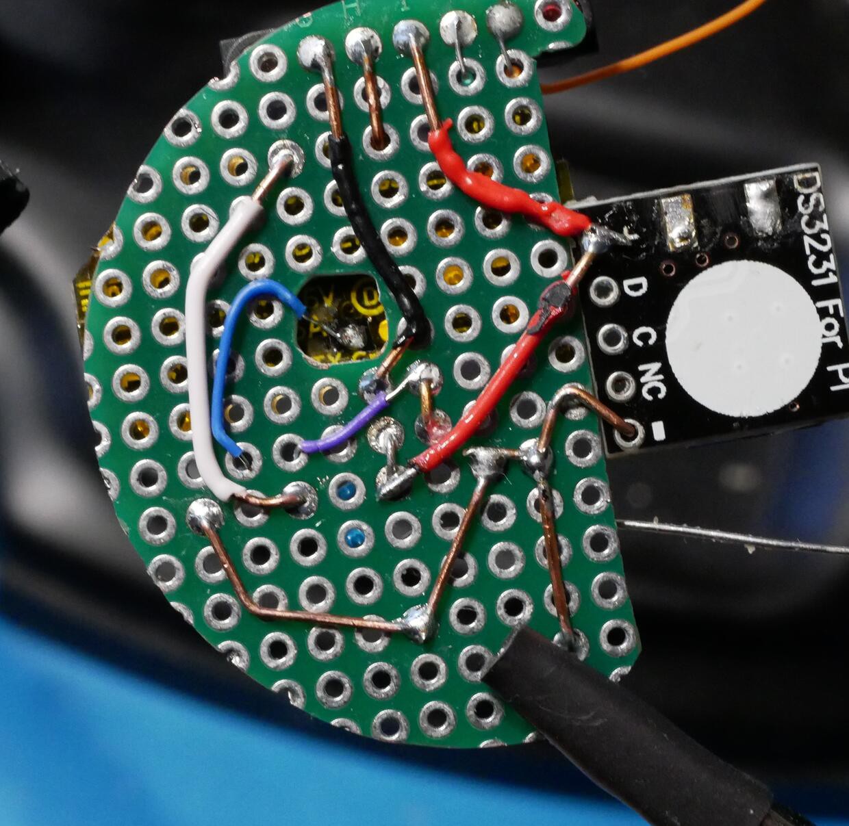
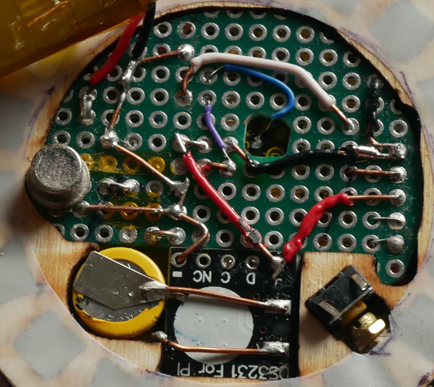
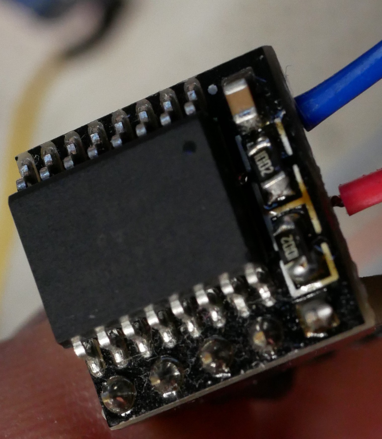
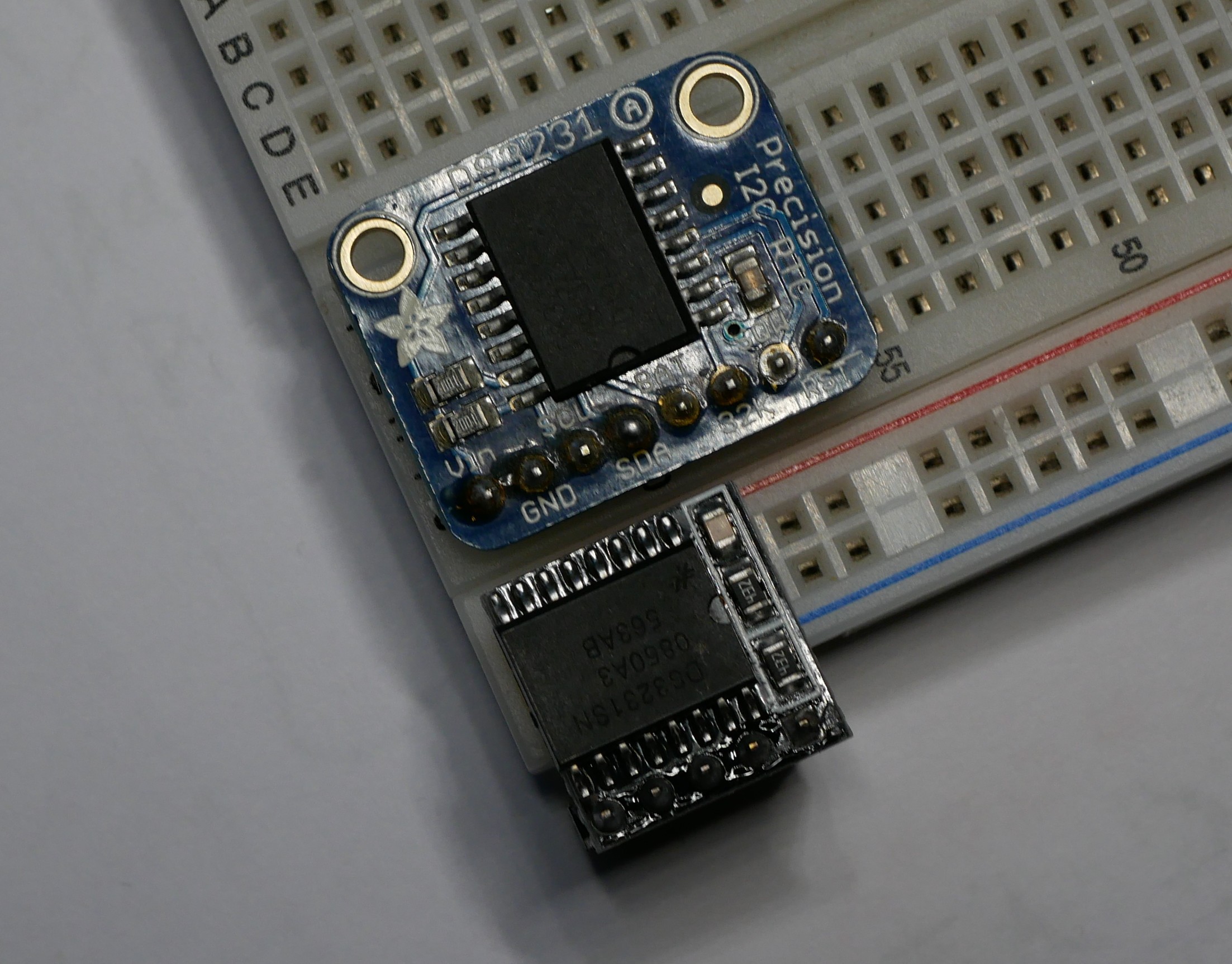
RTC:
for the moment I use a DS3231. 1st prototype used an adafruit modul, for package reasons the 2nd a PiHat version (which needs modification).
Finally I'll plan to use a RV-3032/28-C7 by microcrystal (smallest I could find). Has the nice feature to use a supercap as backup power source, which can be recharged from main battery.
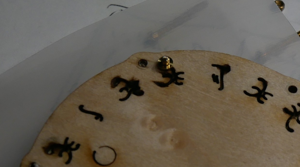
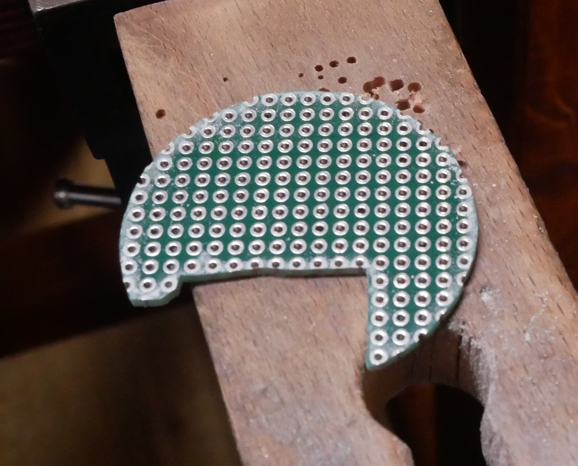
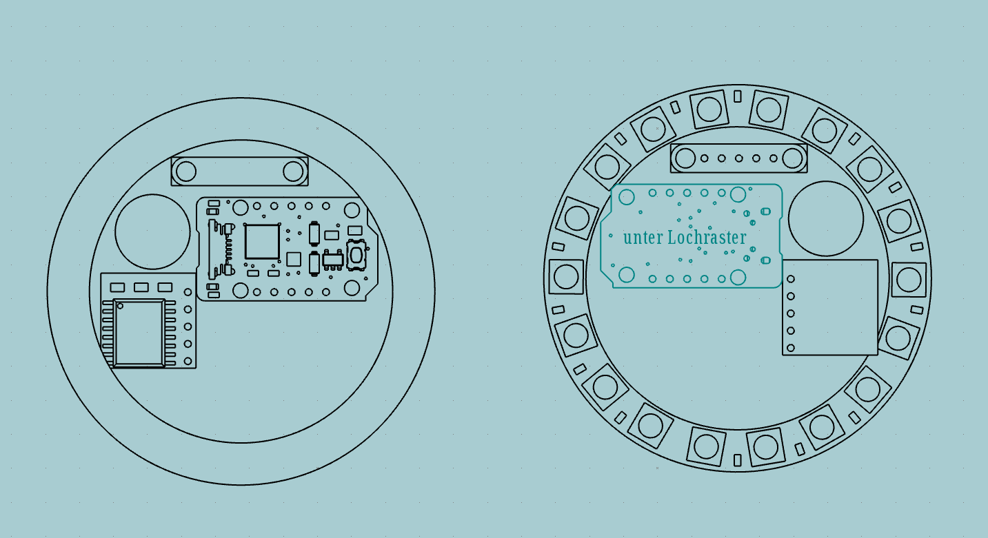
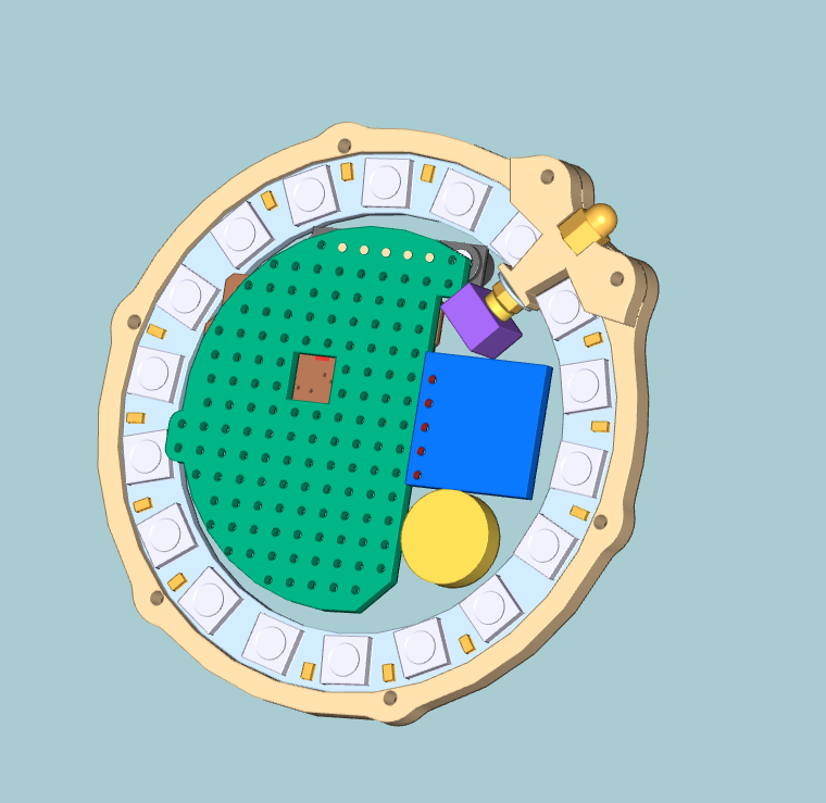
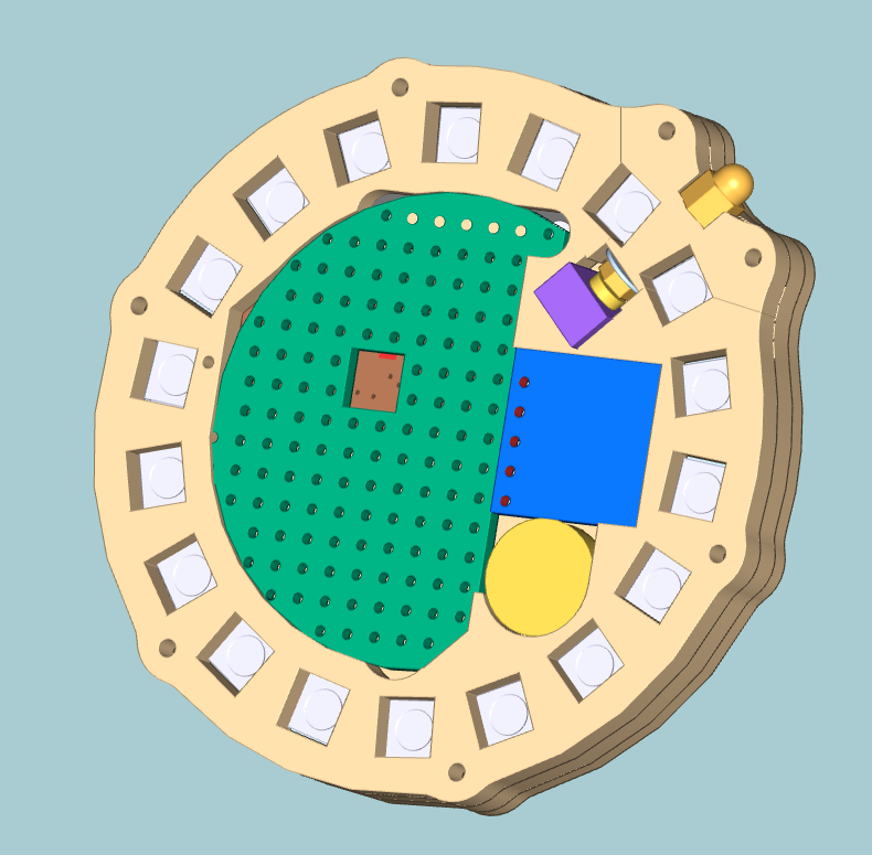
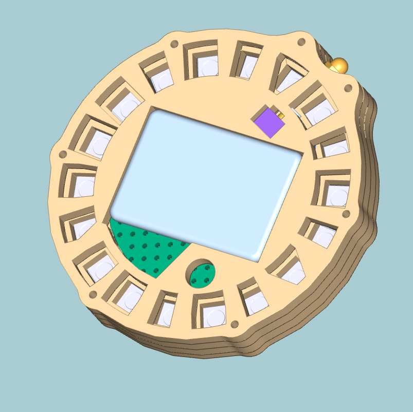
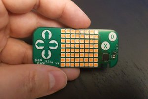
LED Ring
I started with a neopixel 24 ring (still thinking 19 LEDs would be needed). Currently making prototype 2 with a 18 LED Ring. 16 LEDs would work with a trick (in some time there will be a log for that.)
User "Interface"
At the moment just a push button for activating the display of the time. Possibly also a pushbutton for adjusting the time manually (hopefully not needed anyways.
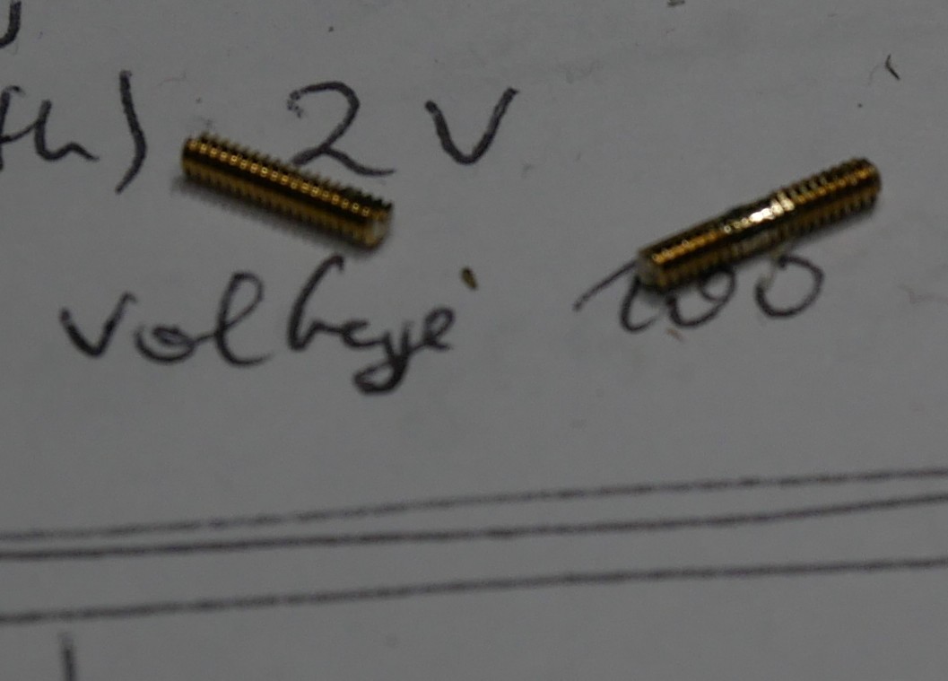
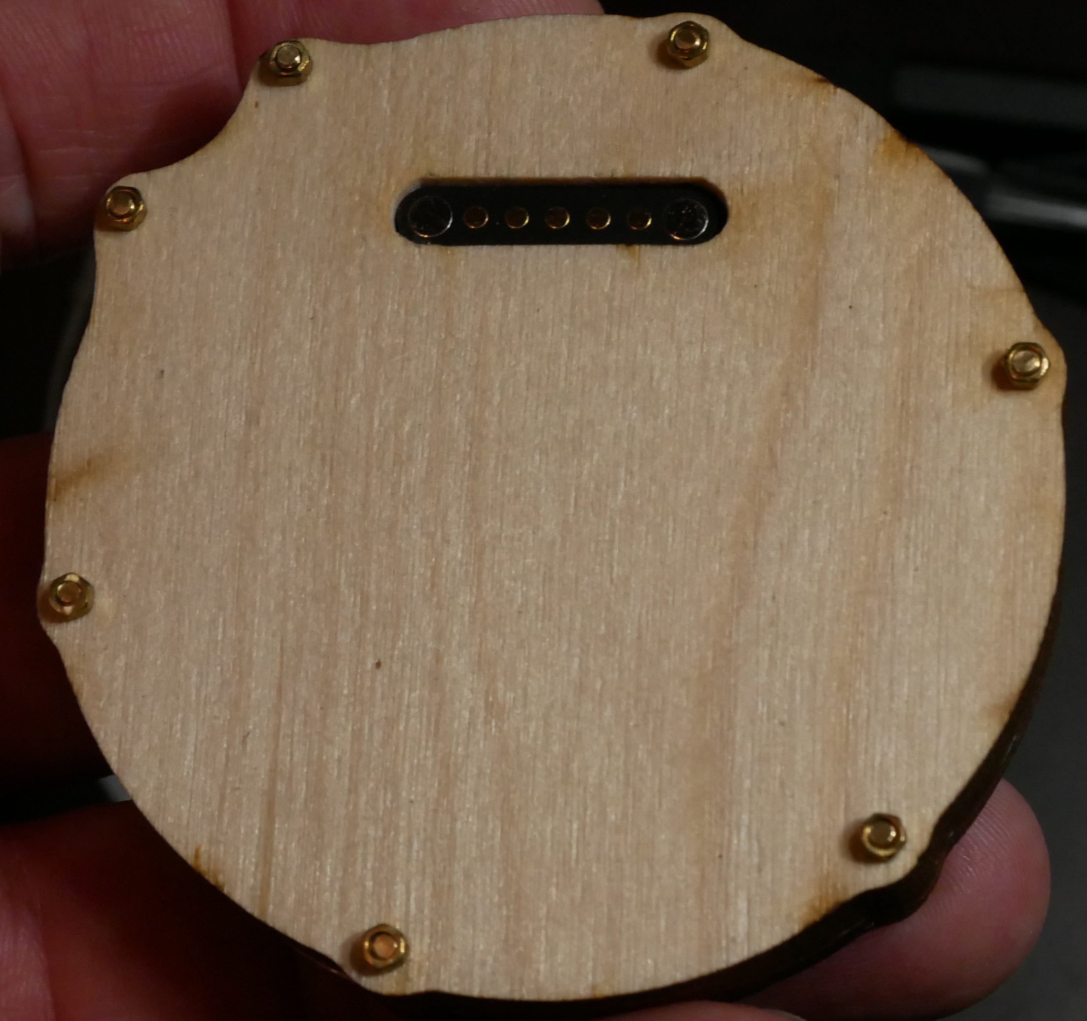
Connection/charging
using a standard USB port makes things easy, since it is available anywhere, but requires the charging logic to be inside the watch. Using a special connector that logic can be placed in a special loading cable/dock, which could carry other I2C devices for time setting or other connectivity.


 deʃhipu
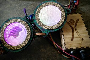
 Ted
Ted
 Jean Simonet
 CriptasticHacker
Hiya [mclien]! Fantastic project and logs you've got here. I wrote this up for the blog and it should publish soon.